NR; Base Station (BS) radio transmission and reception
The present document establishes the minimum RF characteristics and minimum performance requirements of NR and NB-IoT operation in NR in-band Base Station (BS). Clause 1, v20.1.0
Recent versions
Work items
- NR_newRAT-Core Core part: New Radio Access Technology: 135 CRs
- NR_newRAT-Perf Perf. part: New Radio Access Technology: 51 CRs
- NR_HST-Perf Perf. part: NR support for high speed train scenario: 27 CRs
- NR_unlic-Core Core part: NR-based access to unlicensed spectrum: 21 CRs
- NR_RAIL_EU_900MHz-Core Core part: NR_RAIL_EU_900MHz: 19 CRs
- NR_unlic-Perf Perf. part: NR-based access to unlicensed spectrum: 19 CRs
- NR_ext_to_71GHz-Perf Perf. part: Extending current NR operation to 71GHz: 17 CRs
- TEI17 (Small) Technical Enhancements and Improvements for Rel-17: 17 CRs
- NR_FR1_lessthan_5MHz_BW-Core Core part: NR support for dedicated spectrum less than 5MHz for FR1: 16 CRs
- NR_ext_to_71GHz-Core Core part: Extending current NR operation to 71GHz: 15 CRs
By CR count, from 556 harvested CRs up to 2026-09-26. One CR can name more than one work item.
| 3GPP TS 38.104 V20.1.0 (2026-09) | 3GPP TS 38.104 V20.1.0 (2026-09) |
|---|---|
| Technical Specification | Technical Specification |
| 3rd Generation Partnership Project; Technical Specification Group Radio Access Network; NR; Base Station (BS) radio transmission and reception (Release 20) | |
 |
 |
| The present document has been developed within the 3rd Generation Partnership Project (3GPP TM ) and may be further elaborated for the purposes of 3GPP. The present document has not been subject to any approval process by the 3GPP Organizational Partners and shall not be implemented. This Specification is provided for future development work within 3GPP only. The Organizational Partners accept no liability for any use of this Specification. Specifications and Reports for implementation of the 3GPP TM system should be obtained via the 3GPP Organizational Partners’ Publications Offices. |
| 3GPP Postal address 3GPP support office address 650 Route des Lucioles - Sophia Antipolis Valbonne - FRANCE Tel.: +33 4 92 94 42 00 Fax: +33 4 93 65 47 16 Internet http://www.3gpp.org |
| Copyright Notification No part may be reproduced except as authorized by written permission. The copyright and the foregoing restriction extend to reproduction in all media. © 2026, 3GPP Organizational Partners (ARIB, ATIS, CCSA, ETSI, TSDSI, TTA, TTC). All rights reserved. UMTS™ is a Trade Mark of ETSI registered for the benefit of its members 3GPP™ is a Trade Mark of ETSI registered for the benefit of its Members and of the 3GPP Organizational Partners LTE™ is a Trade Mark of ETSI registered for the benefit of its Members and of the 3GPP Organizational Partners GSM® and the GSM logo are registered and owned by the GSM Association |
Contents
Foreword 17
1 Scope 19
2 References 19
3 Definitions, symbols and abbreviations 20
3.1 Definitions 20
3.2 Symbols 25
3.3 Abbreviations 27
4 General 29
4.1 Relationship with other core specifications 29
4.2 Relationship between minimum requirements and test requirements 29
4.3 Conducted and radiated requirement reference points 29
4.3.1 BS type 1-C 29
4.3.2 BS type 1-H 30
4.3.3 BS type 1-O and BS type 2-O 31
4.4 Base station classes 31
4.5 Regional requirements 32
4.6 Applicability of requirements 35
4.7 Requirements for contiguous and non-contiguous spectrum 36
4.8 Requirements for BS capable of multi-band operation 36
4.9 OTA co-location with other base stations 38
5 Operating bands and channel arrangement 39
5.1 General 39
5.2 Operating bands 39
5.3 BS channel bandwidth 42
5.3.1 General 42
5.3.2 Transmission bandwidth configuration 45
5.3.3 Minimum guardband and transmission bandwidth configuration 46
5.3.4 RB alignment 47
5.3.5 BS channel bandwidth per operating band 48
5.3A BS channel bandwidth for CA 52
5.3A.1 Transmission bandwidth configuration for CA 52
5.3A.2 Minimum guardband and transmission bandwidth configuration for CA 52
5.4 Channel arrangement 55
5.4.1 Channel spacing 55
5.4.1.1 Channel spacing for adjacent NR carriers 55
5.4.1.2 Channel spacing for CA 55
5.4.2 Channel raster 56
5.4.2.1 NR-ARFCN and channel raster 56
5.4.2.1A NB-IoT carrier frequency numbering 57
5.4.2.2 Channel raster to resource element mapping 57
5.4.2.3 Channel raster entries for each operating band 57
5.4.3 Synchronization raster 64
5.4.3.1 Synchronization raster and numbering 64
5.4.3.3 Synchronization raster entries for each operating band 65
6 Conducted transmitter characteristics 70
6.1 General 70
6.2 Base station output power 70
6.2.1 General 70
6.2.2 Minimum requirement for BS type 1-C 71
6.2.3 Minimum requirement for BS type 1-H 71
6.2.4 Additional requirements (regional) 71
6.3 Output power dynamics 72
6.3.1 General 72
6.3.2 RE power control dynamic range 72
6.3.2.1 General 72
6.3.2.2 Minimum requirement for BS type 1-C and BS type 1-H 72
6.3.3 Total power dynamic range 73
6.3.3.1 General 73
6.3.3.2 Minimum requirement for BS type 1-C and BS type 1-H 73
6.3.4 NB-IoT RB power dynamic range for NB-IoT operation in NR in-band 74
6.3.4.1 General 74
6.3.4.2 Minimum Requirement 74
6.4 Transmit ON/OFF power 74
6.4.1 Transmitter OFF power 74
6.4.1.1 General 74
6.4.1.2 Minimum requirement for BS type 1-C 74
6.4.1.3 Minimum requirement for BS type 1-H 75
6.4.2 Transmitter transient period 75
6.4.2.1 General 75
6.4.2.2 Minimum requirement for BS type 1-C and BS type 1-H 75
6.4.2.3 Void 76
6.5 Transmitted signal quality 76
6.5.1 Frequency error 76
6.5.1.1 General 76
6.5.1.2 Minimum requirement for BS type 1-C and BS type 1-H 76
6.5.2 Modulation quality 76
6.5.2.1 General 76
6.5.2.2 Minimum Requirement for BS type 1-C and BS type 1-H 76
6.5.2.3 EVM frame structure for measurement 77
6.5.3 Time alignment error 77
6.5.3.1 General 77
6.5.3.2 Minimum requirement for BS type 1-C and BS type 1-H 77
6.6 Unwanted emissions 78
6.6.1 General 78
6.6.2 Occupied bandwidth 79
6.6.2.1 General 79
6.6.2.2 Minimum requirement for BS type 1-C and BS type 1-H 79
6.6.3 Adjacent Channel Leakage Power Ratio 79
6.6.3.1 General 79
6.6.3.2 Limits and Basic limits 79
6.6.3.3 Minimum requirement for BS type 1-C 83
6.6.3.4 Minimum requirement for BS type 1-H 83
6.6.4 Operating band unwanted emissions 83
6.6.4.1 General 83
6.6.4.2 Basic limits 85
6.6.4.2.1 Basic limits for Wide Area BS (Category A) 85
6.6.4.2.2 Basic limits for Wide Area BS (Category B) 86
6.6.4.2.3 Basic limits for Medium Range BS (Category A and B) 90
6.6.4.2.4 Basic limits for Local Area BS (Category A and B) 93
6.6.4.2.4A Basic limits for Local Area and Medium Range BS for bands n46, n96 and n102 (Category A and B) 95
6.6.4.2.5 Basic limits for additional requirements 98
6.6.4.3 Minimum requirements for BS type 1-C 100
6.6.4.4 Minimum requirements for BS type 1-H 100
6.6.5 Transmitter spurious emissions 101
6.6.5.1 General 101
6.6.5.2 Basic limits 101
6.6.5.2.1 General transmitter spurious emissions requirements 101
6.6.5.2.2 Protection of the BS receiver of own or different BS 102
6.6.5.2.3 Additional spurious emissions requirements 102
6.6.5.2.4 Co-location with other base stations 107
6.6.5.3 Minimum requirements for BS type 1-C 108
6.6.5.4 Minimum requirements for BS type 1-H 108
6.7 Transmitter intermodulation 108
6.7.1 General 108
6.7.2 Minimum requirements for BS type 1-C 109
6.7.2.1 Co-location minimum requirements 109
6.7.2.2 Additional requirements 109
6.7.3 Minimum requirements for BS type 1-H 110
6.7.3.1 Co-location minimum requirements 110
6.7.3.2 Intra-system minimum requirements 111
6.7.3.3 Additional requirements 111
7 Conducted receiver characteristics 113
7.1 General 113
7.2 Reference sensitivity level 113
7.2.1 General 113
7.2.2 Minimum requirements for BS type 1-C and BS type 1-H 113
7.3 Dynamic range 119
7.3.1 General 119
7.3.2 Minimum requirement for BS type 1-C and BS type 1-H 119
7.4 In-band selectivity and blocking 131
7.4.1 Adjacent Channel Selectivity (ACS) 131
7.4.1.1 General 131
7.4.1.2 Minimum requirement for BS type 1-C and BS type 1-H 131
7.4.1.3 Void 134
7.4.1.4 Void 134
7.4.2 In-band blocking 134
7.4.2.1 General 134
7.4.2.2 Minimum requirement for BS type 1-C and BS type 1-H 134
7.4.2.3 Void 138
7.4.2.4 Void 138
7.4.2.5 Additional narrowband blocking requirement for Band n100 138
7.5 Out-of-band blocking 138
7.5.1 General 138
7.5.2 Minimum requirement for BS type 1-C and BS type 1-H 139
7.5.3 Co-location minimum requirements for BS type 1-C and BS type 1-H 140
7.5.4 Void 141
7.5.5 Additional out-of-band blocking requirements for the use of RMR bands 141
7.6 Receiver spurious emissions 141
7.6.1 General 141
7.6.2 Basic limits 142
7.6.3 Minimum requirement for BS type 1-C 142
7.6.4 Minimum requirement for BS type 1-H 142
7.7 Receiver intermodulation 143
7.7.1 General 143
7.7.2 Minimum requirement for BS type 1-C and BS type 1-H 143
7.7.3 Additional narrowband intermodulation requirement for Band n100 150
7.8 In-channel selectivity 150
7.8.1 General 150
7.8.2 Minimum requirement for BS type 1-C and BS type 1-H 151
8 Conducted performance requirements 164
8.1 General 164
8.1.1 Scope and definitions 164
8.1.2 Void 164
8.2 Performance requirements for PUSCH 164
8.2.1 Requirements for PUSCH with transform precoding disabled 164
8.2.1.1 General 164
8.2.1.2 Minimum requirements 165
8.2.2 Requirements for PUSCH with transform precoding enabled 175
8.2.2.1 General 175
8.2.2.2 Minimum requirements 175
8.2.3 Requirements for UCI multiplexed on PUSCH 176
8.2.3.1 General 176
8.2.3.2 Minimum requirements 177
8.2.4 Requirements for PUSCH for high speed train 178
8.2.4.1 General 178
8.2.4.2 Minimum requirements 179
8.2.5 Requirements for UL timing adjustment 181
8.2.5.1 Minimum requirements for high speed train 182
8.2.5.2 Minimum requirements for normal mode 183
8.2.6 Requirements for PUSCH 0.001% BLER 184
8.2.6.1 General 184
8.2.6.2 Minimum requirements 184
8.2.7 Requirements for PUSCH repetition Type A 185
8.2.7.1 General 185
8.2.7.2 Minimum requirements 186
8.2.8 Requirements for PUSCH mapping Type B with non-slot transmission 188
8.2.8.1 General 188
8.2.8.2 Minimum requirements 188
8.2.9 Requirements of PUSCH for 2-step RA type 189
8.2.9.1 General 189
8.2.9.2 Minimum requirements 190
8.2.10 Requirements for interlaced PUSCH 190
8.2.10.1 General 190
8.2.10.2 Minimum requirements 191
8.2.11 Performance requirements for CG-UCI multiplexed on interlaced PUSCH 192
8.2.11.1 General 192
8.2.11.2 Minimum requirements 193
8.2.12 Requirements for TB processing over multi-slot PUSCH (TBoMS) 194
8.2.12.1 General 194
8.2.12.2 Minimum requirements 194
8.2.13 Requirements for PUSCH with DM-RS bundling 195
8.2.13.1 General 195
8.2.13.2 Minimum requirements 196
8.2.14 Requirements for PUSCH for ATG 198
8.2.14.1 General 198
8.2.14.2 Minimum requirements 199
8.2.15 Requirements for PUSCH with enhanced DM-RS 200
8.2.15.1 General 200
8.2.16 Enhanced performance requirements for PUSCH with synchronous interference 201
8.2.16.1 General 201
8.2.16.2 Minimum requirements 202
8.3 Performance requirements for PUCCH 206
8.3.1 DTX to ACK probability 206
8.3.1.1 General 206
8.3.1.2 Minimum requirement 207
8.3.2 Performance requirements for PUCCH format 0 207
8.3.2.1 General 207
8.3.2.2 Minimum requirements 207
8.3.3 Performance requirements for PUCCH format 1 208
8.3.3.1 NACK to ACK requirements 208
8.3.3.1.1 General 208
8.3.3.1.2 Minimum requirements 208
8.3.3.2 ACK missed detection requirements 209
8.3.3.2.1 General 209
8.3.3.2.2 Minimum requirements 209
8.3.4 Performance requirements for PUCCH format 2 210
8.3.4.1 ACK missed detection requirements 210
8.3.4.1.1 General 210
8.3.4.1.2 Minimum requirements 210
8.3.4.2 UCI BLER performance requirements 211
8.3.4.2.1 General 211
8.3.4.2.2 Minimum requirements 211
8.3.5 Performance requirements for PUCCH format 3 212
8.3.5.1 General 212
8.3.5.2 Minimum requirements 213
8.3.6 Performance requirements for PUCCH format 4 213
8.3.6.1 General 213
8.3.6.2 Minimum requirement 214
8.3.7 Performance requirements for multi-slot PUCCH 215
8.3.7.1 General 215
8.3.7.2 Performance requirements for multi-slot PUCCH format 1 215
8.3.7.2.1 NACK to ACK requirements 215
8.3.7.2.1.1 General 215
8.3.7.2.1.2 Minimum requirements 216
8.3.7.2.2 ACK missed detection requirements 216
8.3.8 Performance requirements for interlaced PUCCH format 0 216
8.3.8.1 General 216
8.3.8.2 Minimum requirements 217
8.3.9 Performance requirements for interlaced PUCCH format 1 217
8.3.9.1 NACK to ACK requirements 217
8.3.9.1.1 General 217
8.3.9.1.2 Minimum requirements 218
8.3.9.2 ACK missed detection requirements 218
8.3.9.2.1 General 218
8.3.9.2.2 Minimum requirements 218
8.3.10 Performance requirements for interlaced PUCCH format 2 219
8.3.10.1 General 219
8.3.10.2 Minimum requirements 219
8.3.11 Performance requirements for interlaced PUCCH format 3 220
8.3.11.1 General 220
8.3.11.2 Minimum requirements 220
8.3.12 Performance requirements for PUCCH format 1 with DM-RS bundling 221
8.3.12.1 NACK to ACK requirements 221
8.3.12.1.1 General 221
8.3.12.1.2 Minimum requirements 221
8.3.12.2 ACK missed detection requirements 222
8.3.12.2.1 General 222
8.3.12.2.2 Minimum requirements 222
8.3.13 Performance requirements for PUCCH format 3 with DMRS bundling 222
8.3.13.1 General 222
8.3.13.2 Minimum requirements 223
8.3.14 Performance requirements for sub-slot repetition PUCCH format 0 224
8.3.14.1 General 224
8.3.14.2 Minimum requirements 224
8.4 Performance requirements for PRACH 225
8.4.1 PRACH False alarm probability 225
8.4.1.1 General 225
8.4.1.2 Minimum requirement 225
8.4.2 PRACH detection requirements 225
8.4.2.1 General 225
8.4.2.2 Minimum requirements for Normal Mode 225
8.4.2.3 Minimum requirements for high speed train 226
8.4.2.4 Minimum requirements for PRACH with L RA =1151 and L RA =571 227
9 Radiated transmitter characteristics 229
9.1 General 229
9.2 Radiated transmit power 229
9.2.1 General 229
9.2.2 Minimum requirement for BS type 1-H and BS type 1-O 230
9.2.3 Minimum requirement for BS type 2-O 230
9.3 OTA base station output power 230
9.3.1 General 230
9.3.2 Minimum requirement for BS type 1-O 231
9.3.3 Minimum requirement for BS type 2-O 231
9.3.4 Additional requirements (regional) 231
9.4 OTA output power dynamics 231
9.4.1 General 231
9.4.2 OTA RE power control dynamic range 231
9.4.2.1 General 231
9.4.2.2 Minimum requirement for BS type 1-O 231
9.4.3 OTA total power dynamic range 231
9.4.3.1 General 231
9.4.3.2 Minimum requirement for BS type 1-O 232
9.4.3.3 Minimum requirement for BS type 2-O 232
9.5 OTA transmit ON/OFF power 232
9.5.1 General 232
9.5.2 OTA transmitter OFF power 232
9.5.2.1 General 232
9.5.2.2 Minimum requirement for BS type 1-O 232
9.5.2.3 Minimum requirement for BS type 2-O 233
9.5.3 OTA transient period 233
9.5.3.1 General 233
9.5.3.2 Minimum requirement for BS type 1-O 233
9.5.3.3 Minimum requirement for BS type 2-O 233
9.6 OTA transmitted signal quality 233
9.6.1 OTA frequency error 233
9.6.1.1 General 233
9.6.1.2 Minimum requirement for BS type 1-O 233
9.6.1.3 Minimum requirement for BS type 2-O 234
9.6.2 OTA modulation quality 234
9.6.2.1 General 234
9.6.2.2 Minimum Requirement for BS type 1-O 234
9.6.2.3 Minimum Requirement for BS type 2-O 234
9.6.2.3.1 EVM frame structure for measurement 234
9.6.3 OTA time alignment error 234
9.6.3.1 General 234
9.6.3.2 Minimum requirement for BS type 1-O 235
9.6.3.3 Minimum requirement for BS type 2-O 235
9.7 OTA unwanted emissions 235
9.7.1 General 235
9.7.2 OTA occupied bandwidth 236
9.7.2.1 General 236
9.7.2.2 Minimum requirement for BS type 1-O and BS type 2-O 236
9.7.3 OTA Adjacent Channel Leakage Power Ratio (ACLR) 237
9.7.3.1 General 237
9.7.3.2 Minimum requirement for BS type 1-O 237
9.7.3.3 Minimum requirement for BS type 2-O 237
9.7.4 OTA operating band unwanted emissions 239
9.7.4.1 General 239
9.7.4.2 Minimum requirement for BS type 1-O 239
9.7.4.2.1 Additional requirements 240
9.7.4.2.1.1 Protection of DTT 240
9.7.4.2.1.2 Limits in FCC Title 47 240
9.7.4.3 Minimum requirement for BS type 2-O 240
9.7.4.3.1 General 240
9.7.4.3.2 OTA operating band unwanted emission limits (Category A) 241
9.7.4.3.3 OTA operating band unwanted emission limits (Category B) 242
9.7.4.3.4 Additional OTA operating band unwanted emission requirements 243
9.7.5 OTA transmitter spurious emissions 243
9.7.5.1 General 243
9.7.5.2 Minimum requirement for BS type 1-O 244
9.7.5.2.1 General 244
9.7.5.2.2 General OTA transmitter spurious emissions requirements 244
9.7.5.2.3 Protection of the BS receiver of own or different BS 244
9.7.5.2.4 Additional spurious emissions requirements 244
9.7.5.2.5 Co-location with other base stations 244
9.7.5.3 Minimum requirement for BS type 2-O 245
9.7.5.3.1 General 245
9.7.5.3.2 General OTA transmitter spurious emissions requirements 245
9.7.5.3.3 Additional OTA transmitter spurious emissions requirements 246
9.8 OTA transmitter intermodulation 247
9.8.1 General 247
9.8.2 Minimum requirement for BS type 1-O 247
9.8.3 Additional requirements (regional) 248
9.9 OTA spatial emission 249
9.9.1 General 249
9.9.2 Protection of FSS UL 249
9.9.2.1 General 249
9.9.2.2 Minimum requirement for BS type 1-H and BS type 1-O 249
10 Radiated receiver characteristics 251
10.1 General 251
10.2 OTA sensitivity 252
10.2.1 BS type 1-H and BS type 1-O 252
10.2.1.1 General 252
10.2.1.2 Minimum requirement 252
10.2.2 BS type 2-O 252
10.3 OTA reference sensitivity level 253
10.3.1 General 253
10.3.2 Minimum requirement for BS type 1-O 253
10.3.3 Minimum requirement for BS type 2-O 255
10.4 OTA dynamic range 256
10.4.1 General 256
10.4.2 Minimum requirement for BS type 1-O 256
10.5 OTA in-band selectivity and blocking 269
10.5.1 OTA adjacent channel selectivity 269
10.5.1.1 General 269
10.5.1.2 Minimum requirement for BS type 1-O 269
10.5.1.3 Minimum requirement for BS type 2-O 270
10.5.2 OTA in-band blocking 271
10.5.2.1 General 271
10.5.2.2 Minimum requirement for BS type 1-O 271
10.5.2.3 Minimum requirement for BS type 2-O 274
10.6 OTA out-of-band blocking 275
10.6.1 General 275
10.6.2 Minimum requirement for BS type 1-O 275
10.6.2.1 General minimum requirement 275
10.6.2.2 Co-location minimum requirement 276
10.6.3 Minimum requirement for BS type 2-O 276
10.6.3.1 General minimum requirement 276
10.7 OTA receiver spurious emissions 277
10.7.1 General 277
10.7.2 Minimum requirement for BS type 1-O 277
10.7.3 Minimum requirement for BS type 2-O 278
10.8 OTA receiver intermodulation 279
10.8.1 General 279
10.8.2 Minimum requirement for BS type 1-O 279
10.8.3 Minimum requirement for BS type 2-O 285
10.9 OTA in-channel selectivity 286
10.9.1 General 286
10.9.2 Minimum requirement for BS type 1-O 286
10.9.3 Minimum requirement for BS type 2-O 292
11 Radiated performance requirements 294
11.1 General 294
11.1.1 Scope and definitions 294
11.1.2 OTA demodulation branches 294
11.1.3 Void 295
11.2 Performance requirements for PUSCH 295
11.2.1 Requirements for BS type 1-O 295
11.2.1.1 Requirements for PUSCH with transform precoding disabled 295
11.2.1.2 Requirements for PUSCH with transform precoding enabled 295
11.2.1.3 Requirements for UCI multiplexed on PUSCH 295
11.2.1.4 Requirements for PUSCH for high speed train 295
11.2.1.5 Requirements for UL timing adjustment 295
11.2.1.6 Requirements for PUSCH 0.001% BLER 295
11.2.1.7 Requirements for PUSCH repetition Type A 295
11.2.1.8 Requirements for PUSCH mapping Type B with non-slot transmission 295
11.2.1.9 Requirements for PUSCH for 2-step RA type 295
11.2.1.10 Requirements for interlaced PUSCH 295
11.2.1.11 Requirements for CG-UCI multiplexed on interlaced PUSCH 295
11.2.1.12 Requirements for TB processing over multi-slot PUSCH (TBoMS) 295
11.2.1.13 Requirements for PUSCH with DM-RS bundling 296
11.2.1.14 Requirements for PUSCH for ATG 296
11.2.1.15 Requirements for PUSCH with enhanced DM-RS 296
11.2.1.16 Enhanced performance requirements for PUSCH with synchronous interference 296
11.2.2 Requirements for BS type 2-O 296
11.2.2.1 Requirements for PUSCH with transform precoding disabled 296
11.2.2.1.1 General 296
11.2.2.1.2 Minimum requirements 296
11.2.2.2 Requirements for PUSCH with transform precoding enabled 301
11.2.2.2.1 General 301
11.2.2.2.2 Minimum requirements 301
11.2.2.3 Requirements for UCI multiplexed on PUSCH 302
11.2.2.3.1 General 302
11.2.2.3.2 Minimum requirements 303
11.2.2.4 Requirements for PUSCH for 2-step RA type 305
11.2.2.4.1 General 305
11.2.2.4.2 Minimum requirements 306
11.2.2.5 Requirements for PUSCH repetition Type A 306
11.2.2.5.1 General 306
11.2.2.5.2 Minimum requirements 307
11.2.2.6 Requirements for PUSCH mapping Type B with non-slot transmission 308
11.2.2.6.1 General 308
11.2.2.6.2 Minimum requirements 308
11.2.2.7 Requirements for PUSCH for high speed train 309
11.2.2.7.1 General 309
11.2.2.7.2 Minimum requirements 309
11.2.2.8 Requirements for UL timing adjustment 310
11.2.2.8.1 General 310
11.2.2.8.2 Minimum requirements for high speed train 311
11.2.2.9 Requirements for TB processing over multi-slot PUSCH (TBoMS) 312
11.2.2.9.1 General 312
11.2.2.9.2 Minimum requirements 312
11.2.2.10 Requirements for PUSCH with DM-RS bundling 313
11.2.2.10.1 General 313
11.2.2.10.2 Minimum requirements 313
11.3 Performance requirements for PUCCH 314
11.3.1 Requirements for BS type 1-O 314
11.3.1.1 DTX to ACK probability 314
11.3.1.2 Performance requirements for PUCCH format 0 314
11.3.1.3 Performance requirements for PUCCH format 1 314
11.3.1.4 Performance requirements for PUCCH format 2 314
11.3.1.5 Performance requirements for PUCCH format 3 314
11.3.1.6 Performance requirements for PUCCH format 4 314
11.3.1.7 Performance requirements for multi-slot PUCCH 314
11.3.1.8 Performance requirements for PUCCH format 1 with DMRS bundling 314
11.3.1.9 Performance requirements for PUCCH format 3 with DMRS bundling 315
11.3.1.10 Performance requirements for sub-slot repetition PUCCH format 0 315
11.3.2 Requirements for BS type 2-O 315
11.3.2.1 DTX to ACK probability 315
11.3.2.2 Performance requirements for PUCCH format 0. 315
11.3.2.2.1 General 315
11.3.2.2.2 Minimum requirements 315
11.3.2.3 Performance requirements for PUCCH format 1. 316
11.3.2.3.1 NACK to ACK requirements 316
11.3.2.3.1.1 General 316
11.3.2.3.1.2 Minimum requirements 317
11.3.2.3.2 ACK missed detection requirements 318
11.3.2.3.2.1 General 318
11.3.2.3.2.2 Minimum requirements 318
11.3.2.4 Performance requirements for PUCCH format 2 319
11.3.2.4.1 ACK missed detection requirements 319
11.3.2.4.1.1 General 319
11.3.2.4.1.2 Minimum requirements 319
11.3.2.4.2 UCI BLER performance requirements 320
11.3.2.4.2.1 Genera 320
11.3.2.4.2.2 Minimum requirements 320
11.3.2.5 Performance requirements for PUCCH format 3 321
11.3.2.5.1 General 321
11.3.2.5.2 Minimum requirements 321
11.3.2.6 Performance requirements for PUCCH format 4 322
11.3.2.6.1 General 322
11.3.2.6.2 Minimum requirements 323
11.3.2.7 Performance requirements for PUCCH format 1 with DMRS bundling 324
11.3.2.7.1 NACK to ACK requirements 324
11.3.2.7.1.1 General 324
11.3.2.7.1.2 Minimum requirements 325
11.3.2.7.2 ACK missed detection requirements 325
11.3.2.7.2.1 General 325
11.3.2.7.2.2 Minimum requirements 326
11.3.2.8 Performance requirements for PUCCH format 3 with DMRS bunding 326
11.3.2.8.1 General 326
11.3.2.8.2 Minimum requirements 327
11.4 Performance requirements for PRACH 327
11.4.1 Requirements for BS type 1-O 327
11.4.1.1 PRACH False alarm probability 327
11.4.1.2 PRACH detection requirements 327
11.4.2 Requirements for BS type 2-O 327
11.4.2.1 PRACH False alarm probability 327
11.4.2.1.1 General 327
11.4.2.1.2 Minimum requirement 327
11.4.2.2 PRACH detection requirements 328
11.4.2.2.1 General 328
11.4.2.2.2 Minimum requirements for Normal mode 328
11.4.2.2.3 Minimum requirements for high speed train 329
11.4.2.2.4 Minimum requirements for PRACH with L RA =1151 and L RA =571 329
11.4.2.2.5 Minimum requirements for multiple PRACH transmission 330
12 Requirements for SBFD-capable BS 330
12.1 General 330
12.1.1 Applicability of requirements for SBFD-capable BS 330
12.1.2 General SBFD-capable BS Operating Requirements 331
12.1.3 SBFD-capable BS Types and Configuration Constraints 332
12.1.3.1 General 332
12.1.3.2 Configuration-limited SBFD-capable BS 332
12.1.3.3 Configuration-flexible SBFD-capable BS 332
12.2 Conducted transmitter characteristics for SBFD-capable BS 333
12.2.1 General 333
12.2.2 Base station output power for SBFD 333
12.2.2.1 General 333
12.2.2.2 Minimum requirement for BS type 1-H 333
12.2.3 Output power dynamics for SBFD 333
12.2.3.1 General 333
12.2.3.2 RE power control dynamic range for SBFD 333
12.2.3.2.1 General 333
12.2.3.2.2 Minimum requirement for BS type 1-H 333
12.2.3.3 Total power dynamic range for SBFD 333
12.2.3.3.1 General 333
12.2.3.3.2 Minimum requirement for BS type 1-H 334
12.2.4 Transmit ON/OFF power for SBFD 334
12.2.4.1 Transmitter OFF power for SBFD 334
12.2.4.1.1 General 334
12.2.4.1.2 Minimum requirement for BS type 1-H 334
12.2.5 Transmitted signal quality for SBFD 334
12.2.5.1 General 334
12.2.5.2 Minimum requirement for BS type 1-H 334
12.2.6 Unwanted emissions for SBFD 334
12.2.6.1 General 334
12.2.6.2 Minimum requirement for BS type 1-H 334
12.2.7 Transmitter intermodulation for SBFD 334
12.2.7.1 General 334
12.2.7.2 Minimum requirements for BS type 1-H 334
12.2.8 Transient period between SBFD and non-SBFD operation 335
12.2.8.1 General 335
12.2.8.2 Minimum requirement for BS type 1-H 335
12.2.9 In-channel adjacent subband leakage for SBFD 336
12.2.9.1 General 336
12.2.9.2 Limits and Basic limits 336
12.2.9.3 Minimum requirement for BS type 1-H 336
12.3 Conducted receiver characteristics for SBFD-capable BS 337
12.3.1 General 337
12.3.2 Reference sensitivity level 337
12.3.2.1 General 337
12.3.2.2 Minimum requirements for BS type 1-H 337
12.3.3 Dynamic range 337
12.3.3.1 General 337
12.3.3.2 Minimum requirement for BS type 1-H 337
12.3.4 In-band selectivity and blocking for SBFD 337
12.3.4.1 Adjacent Channel Selectivity (ACS) for SBFD 337
12.3.4.1.1 General 337
12.3.4.1.2 Minimum requirement for BS type 1-H 337
12.3.4.2 In-band blocking for SBFD 338
12.3.4.2.1 General 338
12.3.4.2.2 Minimum requirement for BS type 1-H 338
12.3.5 Out-of-band blocking for SBFD 339
12.3.5.1 General 339
12.3.5.2 Minimum requirement for BS type 1-H 339
12.3.5.3 Co-location minimum requirements for BS type 1-H 339
12.3.6 Receiver spurious emissions for SBFD 339
12.3.6.1 General 339
12.3.6.2 Minimum requirement for BS type 1-H 339
12.3.7 In-channel selectivity for SBFD 339
12.3.8 In-channel adjacent subband blocking for SBFD 340
12.3.8.1 General 340
12.3.8.2 Minimum requirement for BS type 1-H 340
12.4 Conducted performance requirements for SBFD-capable BS 341
12.4.1 General 341
12.4.1.1 Scope and definitions 341
12.4.1.2 Void 341
12.4.2 Performance requirements for PUSCH 341
12.4.2.1 Requirements for PUSCH with transform precoding disabled 341
12.4.2.2 Requirements for PUSCH with transform precoding enabled 341
12.4.2.3 Requirements for UCI multiplexed on PUSCH 341
12.4.2.4 Enhanced performance requirements for PUSCH with synchronous interference 342
12.4.2.5 Requirements for PUSCH with UL resource muting 342
12.4.2.5.1 General 342
12.4.2.5.2 Minimum requirements 342
12.4.3 Performance requirements for PUCCH 343
12.4.3.1 DTX to ACK probability 343
12.4.3.2 Performance requirements for PUCCH format 0 343
12.4.3.3 Performance requirements for PUCCH format 1 343
12.4.3.4 Performance requirements for PUCCH format 2 343
12.4.3.5 Performance requirements for PUCCH format 3 344
12.4.3.6 Performance requirements for PUCCH format 4 344
12.4.3.7 Performance requirements for multi-slot PUCCH 344
12.4.4 Performance requirements for PRACH 344
12.5 Radiated transmitter characteristics for SBFD-capable BS 344
12.5.1 General 344
12.5.2 Radiated transmit power for SBFD 344
12.5.2.1 General 344
12.5.2.2 Minimum requirement for BS type 1-H and BS type 1-O 344
12.5.2.3 Minimum requirement for BS type 2-O 344
12.5.3 OTA base station output power for SBFD 345
12.5.3.1 General 345
12.5.3.2 Minimum requirement for BS type 1-O 345
12.5.3.3 Minimum requirement for BS type 2-O 345
12.5.4 OTA output power dynamics for SBFD 345
12.5.4.1 General 345
12.5.4.2 OTA RE power control dynamic range for SBFD 345
12.5.4.2.1 General 345
12.5.4.2.2 Minimum requirement for BS type 1-O 345
12.5.4.3 OTA total power dynamic range for SBFD 345
12.5.4.3.1 General 345
12.5.4.3.2 Minimum requirement for BS type 1-O and BS type 2-O 346
12.5.5 OTA transmit ON/OFF power for SBFD 346
12.5.5.1 OTA transmitter OFF power for SBFD 346
12.5.5.1.1 General 346
12.5.5.1.2 Minimum requirement for BS type 1-O and BS type 2-O 346
12.5.6 OTA transmitted signal quality for SBFD 346
12.5.6.1 General 346
12.5.6.2 Minimum requirement for BS type 1-O and BS type 2-O 346
12.5.7 OTA unwanted emissions for SBFD 346
12.5.7.1 General 346
12.5.7.2 Minimum requirement for BS type 1-O and BS type 2-O 346
12.5.8 OTA Transmitter intermodulation for SBFD 346
12.5.8.1 General 346
12.5.8.2 Minimum requirements for BS type 1-O and BS type 2-O 346
12.5.9 OTA spatial emission for SBFD 347
12.5.9.1 General 347
12.5.9.2 Protection of FSS UL 347
12.5.10 OTA transient period between SBFD and non-SBFD operation 347
12.5.10.1 General 347
12.5.10.2 Minimum requirement for BS type 1-O 348
12.5.10.3 Minimum requirement for BS type 2-O 348
12.5.11 OTA In-channel adjacent subband leakage for SBFD 348
12.5.11.1 General 348
12.5.11.2 Minimum requirement for BS type 1-O 348
12.5.11.3 Minimum requirement for BS type 2-O 348
12.6 Radiated receiver characteristics for SBFD-capable BS 349
12.6.1 General 349
12.6.2 OTA sensitivity for SBFD 349
12.6.2.1 BS type 1-H and BS type 1-O 349
12.6.2.1.1 General 349
12.6.2.1.2 Minimum requirement 349
12.6.3 OTA reference sensitivity level for SBFD 349
12.6.3.1 General 349
12.6.3.2 Minimum requirement for BS type 1-O 349
12.6.3.3 Minimum requirement for BS type 2-O 349
12.6.4 OTA dynamic range for SBFD 349
12.6.4.1 General 349
12.6.4.2 Minimum requirement for BS type 1-O 350
12.6.5 OTA in-band selectivity and blocking for SBFD 350
12.6.5.1 OTA Adjacent Channel Selectivity for SBFD 350
12.6.5.1.1 General 350
12.6.5.1.2 Minimum requirement for BS type 1-O 350
12.6.5.1.3 Minimum requirement for BS type 2-O 350
12.6.5.2 OTA in-band blocking for SBFD 351
12.6.5.2.1 General 351
12.6.5.2.2 Minimum requirement for BS type 1-O 351
12.6.5.2.3 Minimum requirement for BS type 2-O 352
12.6.6 OTA out-of-band blocking for SBFD 353
12.6.6.1 General 353
12.6.6.2 Minimum requirement for BS type 1-O 353
12.6.6.2.1 General minimum requirement 353
12.6.6.2.2 Co-location minimum requirement 353
12.6.6.3 Minimum requirement for BS type 2-O 353
12.6.6.3.1 General minimum requirement 353
12.6.7 OTA receiver spurious emissions for SBFD 353
12.6.7.1 General 353
12.6.7.2 Minimum requirement for BS type 1-O 353
12.6.7.3 Minimum requirement for BS type 2-O 353
12.6.8 OTA in-channel selectivity for SBFD 353
12.6.9 OTA in-channel adjacent subband blocking for SBFD 353
12.6.9.1 General 353
12.6.9.2 Minimum requirement for BS type 1-O 354
12.6.9.3 Minimum requirement for BS type 2-O 355
12.7 Radiated performance requirements for SBFD-capable BS 355
12.7.1 General 355
12.7.1.1 Scope and definitions 355
12.7.1.2 OTA demodulation branches 356
12.7.1.3 Void 356
12.7.2 Performance requirements for PUSCH 356
12.7.2.1 Requirements for BS type 1-O 356
12.7.2.1.1 Requirements for PUSCH with transform precoding disabled 356
12.7.2.1.2 Requirements for PUSCH with transform precoding enabled 356
12.7.2.1.3 Requirements for UCI multiplexed on PUSCH 356
12.7.2.1.4 Enhanced performance requirements for PUSCH with synchronous interference 356
12.7.2.1.5 Requirements for PUSCH with UL resource muting 356
12.7.2.2 Requirements for BS type 2-O 357
12.7.2.2.1 Requirements for PUSCH with transform precoding disabled 357
12.7.2.2.2 Requirements for PUSCH with transform precoding enabled 357
12.7.2.2.3 Requirements for UCI multiplexed on PUSCH 357
12.7.3 Performance requirements for PUCCH 357
12.7.3.1 Requirements for BS type 1-O 357
12.7.3.1.1 DTX to ACK probability 357
12.7.3.1.2 Performance requirements for PUCCH format 0 357
12.7.3.1.3 Performance requirements for PUCCH format 1 357
12.7.3.1.4 Performance requirements for PUCCH format 2 357
12.7.3.1.5 Performance requirements for PUCCH format 3 357
12.7.3.1.6 Performance requirements for PUCCH format 4 357
12.7.3.1.7 Performance requirements for multi-slot PUCCH 357
12.7.3.2 Requirements for BS type 2-O 358
12.7.3.2.1 DTX to ACK probability 358
12.7.3.2.2 Performance requirements for PUCCH format 0. 358
12.7.3.2.3 Performance requirements for PUCCH format 1. 358
12.7.3.2.4 Performance requirements for PUCCH format 2 358
12.7.3.2.5 Performance requirements for PUCCH format 3 358
12.7.3.2.6 Performance requirements for PUCCH format 4 358
12.7.4 Performance requirements for PRACH 358
12.7.4.1 Requirements for BS type 1-O 358
12.7.4.1.1 PRACH False alarm probability 358
12.7.4.1.2 PRACH detection requirements 358
12.7.4.2 Requirements for BS type 2-O 359
12.7.4.2.1 PRACH False alarm probability 359
12.7.4.2.2 PRACH detection requirements 359
Annex A (normative): Reference measurement channels 360
A.1 Fixed Reference Channels for reference sensitivity level, ACS, in-band blocking, out-of-band blocking, receiver intermodulation and in-channel selectivity (QPSK, R=1/3) 360
A.2 Fixed Reference Channels for dynamic range (16QAM, R=2/3) 363
A.3 Fixed Reference Channels for performance requirements (QPSK, R=193/1024) 365
A.3A Fixed Reference Channels for performance requirements (QPSK, R=99/1024) 373
A.3B Fixed Reference Channels for performance requirements (QPSK, R=308/1024) 375
A.4 Fixed Reference Channels for performance requirements (16QAM, R=658/1024) 379
A.5 Fixed Reference Channels for performance requirements (64QAM, R=567/1024) 385
A.6 PRACH Test preambles 389
A.7 Fixed Reference Channels for performance requirements (16QAM, R=434/1024) 390
A.8 Fixed Reference Channels for performance requirements (QPSK, R=157/1024) 392
A.9 Fixed Reference Channels for performance requirements (256QAM, R=682.5/1024) 393
A.10 Fixed Reference Channels for performance requirements (64QAM, R=517/1024) 395
A.11 Fixed Reference Channels for performance requirements (64QAM, R=438/1024) 399
A.12 Void 400
Annex B (normative): Error Vector Magnitude (FR1) 402
B.1 Reference point for measurement 402
B.2 Basic unit of measurement 402
B.3 Modified signal under test 403
B.4 Estimation of frequency offset 403
B.5 Estimation of time offset 403
B.5.1 General 403
B.5.2 Window length 404
B.6 Estimation of TX chain amplitude and frequency response parameters 405
B.7 Averaged EVM 407
B.8 Averaged EVM for FR1 SBFD-capable BS 408
B.9 Interference model for enhanced performance requirements for PUSCH with synchronous interference 409
B.9.1 Interference to Noise ratio (INR) 409
B.9.2 Interference model for synchronous scenario 409
Annex C (normative): Error Vector Magnitude (FR2) 410
C.1 Reference point for measurement 410
C.2 Basic unit of measurement 410
C.3 Modified signal under test 411
C.4 Estimation of frequency offset 411
C.5 Estimation of time offset 411
C.5.1 General 411
C.5.2 Window length 412
C.6 Estimation of TX chain amplitude and frequency response parameters 413
C.7 Averaged EVM 415
C.8 Averaged EVM for FR2-1 SBFD-capable BS 416
Annex D (normative): Characteristics of the interfering signals 417
Annex E: Void 418
Annex F (normative): Relationship between EIRP based regulatory requirements and 3GPP requirements 419
F.1 General 419
F.2 Relationship between EIRP based regulatory requirements and conducted requirements 419
F.3 Relationship between EIRP based regulatory requirements and OTA requirements 420
Annex G (Normative): Propagation conditions 421
G.1 Static propagation condition 421
G.1.1 BS Receiver with 2Rx 421
G.2 Multi-path fading propagation conditions 421
G.2.1 Delay profiles 421
G.2.1.1 Delay profiles for FR1 422
G.2.1.2 Delay profiles for FR2 423
G.2.2 Combinations of channel model parameters 425
G.2.3 MIMO Channel Correlation Matrices 426
G.2.3.1 MIMO Correlation Matrices using Uniform Linear Array (ULA) 426
G.2.3.1.1 Definition of MIMO Correlation Matrices 426
G.2.3.1.2 MIMO Correlation Matrices at High, Medium and Low Level 430
G.2.3.2 Multi-Antenna channel models using cross polarized antennas 432
G.2.3.2.1 Definition of MIMO Correlation Matrices using cross polarized antennas 433
G.2.3.2.2 Spatial Correlation Matrices at UE and gNB sides 433
G.2.3.2.2.1 Spatial Correlation Matrices at UE side 433
G.2.3.2.2.2 Spatial Correlation Matrices at gNB side 434
G.2.3.2.3 MIMO Correlation Matrices using cross polarized antennas 434
G.3 High speed train condition 434
G.4 Moving propagation conditions 439
Annex H (informative): Change history 441
Foreword
This Technical Specification has been produced by the 3rd Generation Partnership Project (3GPP).
The contents of the present document are subject to continuing work within the TSG and may change following formal TSG approval. Should the TSG modify the contents of the present document, it will be re-released by the TSG with an identifying change of release date and an increase in version number as follows:
Version x.y.z
where:
x the first digit:
1 presented to TSG for information;
2 presented to TSG for approval;
3 or greater indicates TSG approved document under change control.
y the second digit is incremented for all changes of substance, i.e. technical enhancements, corrections, updates, etc.
z the third digit is incremented when editorial only changes have been incorporated in the document.
In the present document, modal verbs have the following meanings:
shall indicates a mandatory requirement to do something
shall not indicates an interdiction (prohibition) to do something
The constructions “shall” and “shall not” are confined to the context of normative provisions, and do not appear in Technical Reports.
The constructions “must” and “must not” are not used as substitutes for “shall” and “shall not”. Their use is avoided insofar as possible, and they are not used in a normative context except in a direct citation from an external, referenced, non-3GPP document, or so as to maintain continuity of style when extending or modifying the provisions of such a referenced document.
should indicates a recommendation to do something
should not indicates a recommendation not to do something
may indicates permission to do something
need not indicates permission not to do something
The construction “may not” is ambiguous and is not used in normative elements. The unambiguous constructions “might not” or “shall not” are used instead, depending upon the meaning intended.
can indicates that something is possible
cannot indicates that something is impossible
The constructions “can” and “cannot” are not substitutes for “may” and “need not”.
will indicates that something is certain or expected to happen as a result of action taken by an agency the behaviour of which is outside the scope of the present document
will not indicates that something is certain or expected not to happen as a result of action taken by an agency the behaviour of which is outside the scope of the present document
might indicates a likelihood that something will happen as a result of action taken by some agency the behaviour of which is outside the scope of the present document
might not indicates a likelihood that something will not happen as a result of action taken by some agency the behaviour of which is outside the scope of the present document
In addition:
is (or any other verb in the indicative mood) indicates a statement of fact
is not (or any other negative verb in the indicative mood) indicates a statement of fact
The constructions “is” and “is not” do not indicate requirements.
1 Scope
The present document establishes the minimum RF characteristics and minimum performance requirements of NR and NB-IoT operation in NR in-band Base Station (BS).
2 References
The following documents contain provisions which, through reference in this text, constitute provisions of the present document.
-
References are either specific (identified by date of publication, edition number, version number, etc.) or non-specific.
-
For a specific reference, subsequent revisions do not apply.
-
For a non-specific reference, the latest version applies. In the case of a reference to a 3GPP document (including a GSM document), a non-specific reference implicitly refers to the latest version of that document in the same Release as the present document .
[1] 3GPP TR 21.905: “Vocabulary for 3GPP Specifications”.
[2] ITU-R Recommendation SM.329: “Unwanted emissions in the spurious domain”.
[3] Recommendation ITU-R SM.328: “Spectra and bandwidth of emissions”.
[4] 3GPP TR 25.942: “RF system scenarios”.
[5] 3GPP TS 38.141-1: “NR; Base Station (BS) conformance testing; Part 1: Conducted conformance testing”.
[6] 3GPP TS 38.141-2: “NR; Base Station (BS) conformance testing; Part 2: Radiated conformance testing”.
[7] Recommendation ITU-R M.1545: “Measurement uncertainty as it applies to test limits for the terrestrial component of International Mobile Telecommunications-2000”.
[8] “Title 47 of the Code of Federal Regulations (CFR)”, Federal Communications Commission.
[9] 3GPP TS 38.211: “NR; Physical channels and modulation”.
[10] 3GPP TS 38.213: “NR; Physical layer procedures for control”.
[11] 3GPP TS 38.331: “NR; Radio Resource Control (RRC); Protocol specification”.
[12] ECC/DEC/(17)06: “The harmonised use of the frequency bands 1427-1452 MHz and 1492-1518 MHz for Mobile/Fixed Communications Networks Supplemental Downlink (MFCN SDL)”
[13] 3GPP TS 36.104: “Evolved Universal Terrestrial Radio Access (E-UTRA); Base Station (BS) radio transmission and reception”.
[14] 3GPP TS 37.105: “Active Antenna System (AAS) Base Station (BS) transmission and reception”.
[15] 3GPP TS 38.212: “NR; Multiplexing and channel coding”.
[16] 3GPP TR 38.901: “Study on channel model for frequencies from 0.5 to 100 GHz”
[17] 3GPP TS 38.101-1: “NR; User Equipment (UE) radio transmission and reception; Part 1: Range 1 Standalone”.
[18] 3GPP TS 38.101-2: “NR; User Equipment (UE) radio transmission and reception; Part 2: Range 2 Standalone”
[19] ERC Recommendation 74-01, “Unwanted emissions in the spurious domain”.
[20] 3GPP TS 37.213: “Physical layer procedures for shared spectrum channel access”.
[21] ECC Decision(20)02: “Harmonised use of the paired frequency bands 874.4-880.0 MHz and 919.4-925.0 MHz and of the unpaired frequency band 1900-1910 MHz for Railway Mobile Radio (RMR)”
[22] 3GPP TR 38.852: Introduction of 1900MHz NR band for Europe for Rail Mobile Radio (RMR)
[23] 3GPP TR 38.853: Introduction of 900MHz NR band for Europe for Rail Mobile Radio (RMR)
[24] FCC Report And Order And Further Notice Of Proposed Rulemaking FCC 20-51, April 2020.
[25] FCC Order DA 20-48, April 2020
[26] Commission Implementing Decision (EU) 2020/590 of 24 April 2020 amending Decision (EU) 2019/784 as regards an update of relevant technical conditions applicable to the 24,25-27,5 GHz frequency band .
[27] ITU World Radiocommunication Conference 2023 (WRC-23) Final Acts, Resolution 220.
[28] ITU Radio Regulations, Edition of 2024, https://www.itu.int/pub/R-REG-RR-2024 .
[29] 3GPP TS 25.104: “Base Station (BS) radio transmission and reception (FDD)”.
3 Definitions, symbols and abbreviations
3.1 Definitions
For the purposes of the present document, the terms and definitions given in 3GPP TR 21.905 [1] and the following apply. A term defined in the present document takes precedence over the definition of the same term, if any, in 3GPP TR 21.905 [1].
Aggregated BS Channel Bandwidth: The RF bandwidth in which a Base Station transmits and receives multiple contiguously aggregated carriers. The aggregated BS channel bandwidth is measured in MHz.
antenna connector: connector at the conducted interface of the BS type 1-C
active transmitter unit: transmitter unit which is ON, and has the ability to send modulated data streams that are parallel and distinct to those sent from other transmitter units to a BS type 1-C antenna connector , or to one or more BS type 1-H TAB connectors at the transceiver array boundary
Base Station RF Bandwidth : RF bandwidth in which a base station transmits and/or receives single or multiple carrier(s) within a supported operating band
NOTE: In single carrier operation, the Base Station RF Bandwidth is equal to the BS channel bandwidth .
Base Station RF Bandwidth edge: frequency of one of the edges of the Base Station RF Bandwidth .
basic limit: emissions limit relating to the power supplied by a single transmitter to a single antenna transmission line in ITU-R SM.329 [2] used for the formulation of unwanted emission requirements for FR1
beam: beam (of the antenna) is the main lobe of the radiation pattern of an antenna array
NOTE: For certain BS antenna array , there may be more than one beam.
beam centre direction: direction equal to the geometric centre of the half-power contour of the beam
beam direction pair: data set consisting of the beam centre direction and the related beam peak direction
beam peak direction: direction where the maximum EIRP is found
beamwidth: beam which has a half-power contour that is essentially elliptical, the half-power beamwidths in the two pattern cuts that respectively contain the major and minor axis of the ellipse
BS channel bandwidth : RF bandwidth supporting a single NR RF carrier with the transmission bandwidth configured in the uplink or downlink
NOTE 1: The BS channel bandwidth is measured in MHz and is used as a reference for transmitter and receiver RF requirements.
NOTE 2: It is possible for the BS to transmit to and/or receive from one or more UE bandwidth parts that are smaller than or equal to the BS transmission bandwidth configuration , in any part of the BS transmission bandwidth configuration .
BS transmission bandwidth configuration : set of resource blocks located within the BS channel bandwidth which may be used for transmitting or receiving by the BS
BS transmission bandwidth configuration for SBFD operation : set of resource blocks located within the BS channel bandwidth which may be used for transmitting or/and receiving by the SBFD-capable BS
BS type 1-C: NR base station operating at FR1 with requirements set consisting only of conducted requirements defined at individual antenna connectors
BS type 1-H: NR base station operating at FR1 with a requirement set consisting of conducted requirements defined at individual TAB connectors and OTA requirements defined at RIB
BS type 1-O: NR base station operating at FR1 with a requirement set consisting only of OTA requirements defined at the RIB
BS type 2-O: NR base station operating at FR2 with a requirement set consisting only of OTA requirements defined at the RIB
Channel edge: lowest or highest frequency of the NR carrier, separated by the BS channel bandwidth .
Carrier aggregation: aggregation of two or more component carriers in order to support wider transmission bandwidths
Carrier aggregation configuration: a set of one or more operating bands across which the BS aggregates carriers with a specific set of technical requirements
co-location reference antenna : a passive antenna used as reference for base station to base station co-location requirements
Contiguous carriers: set of two or more carriers configured in a spectrum block where there are no RF requirements based on co-existence for un-coordinated operation within the spectrum block.
Contiguous spectrum: spectrum consisting of a contiguous block of spectrum with no sub-block gap(s) .
directional requirement: requirement which is applied in a specific direction within the OTA coverage range for the Tx and when the AoA of the incident wave of a received signal is within the OTA REFSENS RoAoA or the minSENS RoAoA as appropriate for the receiver
Enhanced channel raster: channel raster with a 10 kHz granularity in bands with a 100 kHz channel raster.
equivalent isotropic radiated power: equivalent power radiated from an isotropic directivity device producing the same field intensity at a point of observation as the field intensity radiated in the direction of the same point of observation by the discussed device
NOTE: Isotropic directivity is equal in all directions (i.e. 0 dBi).
equivalent isotropic sensitivity: sensitivity for an isotropic directivity device equivalent to the sensitivity of the discussed device exposed to an incoming wave from a defined AoA
NOTE 1: The sensitivity is the minimum received power level at which specific requirement is met.
NOTE 2: Isotropic directivity is equal in all directions (i.e. 0 dBi).
fractional bandwidth: fractional bandwidth FBW is defined as
Highest Carrier: The carrier with the highest carrier frequency transmitted/received in a specified frequency band.
Inter-band carrier aggregation: carrier aggregation of component carriers in different operating bands .
NOTE: Carriers aggregated in each band can be contiguous or non-contiguous.
Inter-band gap : The frequency gap between two supported consecutive operating bands .
Intra-band contiguous carrier aggregation: contiguous carriers aggregated in the same operating band .
Intra-band non-contiguous carrier aggregation: non-contiguous carriers aggregated in the same operating band .
Inter RF Bandwidth gap: frequency gap between two consecutive Base Station RF Bandwidths that are placed within two supported operating bands
Lowest Carrier: The carrier with the lowest carrier frequency transmitted/received in a specified frequency band.
Lower sub-block edge: frequency at the lower edge of one sub-block .
NOTE: It is used as a frequency reference point for both transmitter and receiver requirements.
maximum carrier output power: mean power level measured per carrier at the indicated interface, during the transmitter ON period in a specified reference condition
maximum carrier TRP output power: mean power level measured per RIB during the transmitter ON period for a specific carrier in a specified reference condition and corresponding to the declared rated carrier TRP output power (P rated,c,TRP )
maximum total output power: mean power level measured within the operating band at the indicated interface, during the transmitter ON period in a specified reference condition
maximum total TRP output power: mean power level measured per RIB during the transmitter ON period in a specified reference condition and corresponding to the declared rated total TRP output power (P rated,t,TRP )
measurement bandwidth : RF bandwidth in which an emission level is specified
minSENS: the lowest declared EIS value for the OSDD’s declared for OTA sensitivity requirement.
minSENS RoAoA: The reference RoAoA associated with the OSDD with the lowest declared EIS
multi-band connector : Antenna Connector of BS type 1-C or TAB connector of BS type 1-H associated with a transmitter or receiver that is characterized by the ability to process two or more carriers in common active RF components simultaneously, where at least one carrier is configured at a different operating band than the other carrier(s) and where this different operating band is not a sub-band or superseding-band of another supported operating band
multi-band RIB: operating band specific RIB associated with a transmitter or receiver that is characterized by the ability to process two or more carriers in common active RF components simultaneously, where at least one carrier is configured at a different operating band than the other carrier(s) and where this different operating band is not a sub-band or superseding-band of another supported operating band
Multi-carrier transmission configuration: set of one or more contiguous or non-contiguous carriers that a NR BS is able to transmit simultaneously according to the manufacturer’s specification.
NB-IoT operation in NR in-band: NB-IoT is operating in-band when it is located within a NR transmission bandwidth configuration plus 15 kHz at each edge but not within the NR minimum guard band GB Channel .
NB-IoT operation in NR guard band: NB-IoT is operating in guard band when it is located within a NR BS channel bandwidth but is not NB-IoT operation in NR in-band.
Non-contiguous spectrum: spectrum consisting of two or more sub-blocks separated by sub-block gap(s) .
Non-SBFD operation : SBFD-capable BS operation in non-SBFD symbols.
operating band: frequency range in which NR operates (paired or unpaired), that is defined with a specific set of technical requirements
NOTE: The operating band (s) for a BS is declared by the manufacturer according to the designations in tables 5.2-1 and 5.2-2.
OTA coverage range : a common range of directions within which TX OTA requirements that are neither specified in the OTA peak directions sets nor as TRP requirement are intended to be met
OTA peak directions set: set(s) of beam peak directions within which certain TX OTA requirements are intended to be met, where all OTA peak directions set(s) are subsets of the OTA coverage range
NOTE: The beam peak directions are related to a corresponding contiguous range or discrete list of beam centre directions by the beam direction pairs included in the set.
OTA REFSENS RoAoA: the RoAoA determined by the contour defined by the points at which the achieved EIS is 3dB higher than the achieved EIS in the reference direction assuming that for any AoA, the receiver gain is optimized for that AoA
NOTE: This contour will be related to the average element/sub-array radiation pattern 3dB beamwidth.
OTA sensitivity directions declaration: set of manufacturer declarations comprising at least one set of declared minimum EIS values (with BS channel bandwidth ), and related directions over which the EIS applies
NOTE: All the directions apply to all the EIS values in an OSDD.
polarization match: condition that exists when a plane wave, incident upon an antenna from a given direction, has a polarization that is the same as the receiving polarization of the antenna in that direction
radiated interface boundary : operating band specific radiated requirements reference where the radiated requirements apply
NOTE: For requirements based on EIRP/EIS, the radiated interface boundary is associated to the far-field region
Radio Bandwidth: frequency difference between the upper edge of the highest used carrier and the lower edge of the lowest used carrier
Railway Mobile Radio: railway operations encompassing GSM-R and its successor(s), including the Future Railway Mobile Communication System (FRMCS); in the context of this specification the Railway Mobile Radio is limited to NR operation in band n100, or n101
rated beam EIRP: For a declared beam and beam direction pair , the rated beam EIRP level is the maximum power that the base station is declared to radiate at the associated beam peak direction during the transmitter ON period
rated carrier output power: mean power level associated with a particular carrier the manufacturer has declared to be available at the indicated interface, during the transmitter ON period in a specified reference condition
rated carrier TRP output power: mean power level declared by the manufacturer per carrier, for BS operating in single carrier, multi-carrier, or carrier aggregation configurations that the manufacturer has declared to be available at the RIB during the transmitter ON period
rated total output power: mean power level associated with a particular operating band the manufacturer has declared to be available at the indicated interface, during the transmitter ON period in a specified reference condition
rated total TRP output power: mean power level declared by the manufacturer, that the manufacturer has declared to be available at the RIB during the transmitter ON period
reference beam direction pair: declared beam direction pair , including reference beam centre direction and reference beam peak direction where the reference beam peak direction is the direction for the intended maximum EIRP within the OTA peak directions set
receiver target: AoA in which reception is performed by BS types 1-H or BS type 1-O
receiver target redirection range: union of all the sensitivity RoAoA achievable through redirecting the receiver target related to particular OSDD
receiver target reference direction: direction inside the OTA sensitivity directions declaration declared by the manufacturer for conformance testing. For an OSDD without receiver target redirection range , this is a direction inside the sensitivity RoAoA
reference RoAoA : the sensitivity RoAoA associated with the receiver target reference direction for each OSDD.
requirement set: one of the NR base station requirement’s set as defined for BS type 1-C , BS type 1-H , BS type 1-O , and BS type 2-O
SBFD DUD operation: SBFD operation in the carrier on which one SBFD UL subband and two DL subbands are configured, with the UL subband configured in the middle of two SBFD DL subbands.
SBFD DU operation: SBFD operation in the carrier on which one SBFD UL subband and one DL subband are configured, with the UL subband configured higher than the DL subband in frequency.
SBFD operation : SBFD-capable BS operation in SBFD symbols.
SBFD UD operation: SBFD operation in the carrier on which one SBFD UL subband and one DL subband are configured, with the UL subband configured lower than the DL subband in frequency.
SBFD-capable BS: NR base station which is capable of SBFD operation.
SBFD symbol: An OFDM symbol configured for simultaneous uplink transmission and downlink reception within separate non-overlapping frequency subbands on the same carrier.
sensitivity RoAoA: RoAoA within the OTA sensitivity directions declaration , within which the declared EIS(s) of an OSDD is intended to be achieved at any instance of time for a specific BS direction setting
single-band connector: BS type 1-C antenna connector or BS type 1-H TAB connector supporting operation either in a single operating band only, or in multiple operating bands but does not meet the conditions for a multi-band connector .
single-band RIB: operating band specific RIB supporting operation either in a single operating band only, or in multiple operating bands but does not meet the conditions for a multi-band RIB .
square filter : filter with an ideal square frequency response, used as a mathematical reference to integrate signal power over a specific channel bandwidth
sub-band : A sub-band of an operating band contains a part of the uplink and downlink frequency range of the operating band.
sub-block bandwidth: bandwidth of one sub-block .
sub-block: one contiguous allocated block of spectrum for transmission and reception by the same base station
NOTE: There may be multiple instances of sub-blocks within a Base Station RF Bandwidth .
sub-block gap: frequency gap between two consecutive sub-blocks within a Base Station RF Bandwidth , where the RF requirements in the gap are based on co-existence for un-coordinated operation
superseding-band : A superseding-band of an operating band includes the whole of the uplink and downlink frequency range of the operating band.
TAB connector: transceiver array boundary connector
TAB connector RX min cell group: operating band specific declared group of TAB connectors to which BS type 1-H conducted RX requirements are applied
NOTE: Within this definition, the group corresponds to the group of TAB connectors which are responsible for receiving a cell when the BS type 1-H setting corresponding to the declared minimum number of cells with reception on all TAB connectors supporting an operating band , but its existence is not limited to that condition
TAB connector TX min cell group: operating band specific declared group of TAB connectors to which BS type 1-H conducted TX requirements are applied.
NOTE: Within this definition, the group corresponds to the group of TAB connectors which are responsible for transmitting a cell when the BS type 1-H setting corresponding to the declared minimum number of cells with transmission on all TAB connectors supporting an operating band , but its existence is not limited to that condition
total radiated power: is the total power radiated by the antenna
NOTE: The total radiated power is the power radiating in all direction for two orthogonal polarizations. Total radiated power is defined in both the near-field region and the far-field region
transceiver array boundary: conducted interface between the transceiver unit array and the composite antenna
transmission bandwidth: RF Bandwidth of an instantaneous transmission from a UE or BS, measured in resource block units
transmitter OFF period: time period during which the BS transmitter is not allowed to transmit
transmitter ON period: time period during which the BS transmitter is transmitting data and/or reference symbols
transmitter transient period: time period during which the transmitter is changing from the OFF period to the ON period or vice versa
UE transmission bandwidth configuration: set of resource blocks located within the UE channel bandwidth which may be used for transmitting or receiving by the UE
upper sub-block edge: frequency at the upper edge of one sub-block .
NOTE: It is used as a frequency reference point for both transmitter and receiver requirements.
3.2 Symbols
For the purposes of the present document, the following symbols apply:
Percentage of the mean transmitted power emitted outside the occupied bandwidth on the assigned channel
BeW θ,REFSENS Beamwidth equivalent to the OTA REFSENS RoAoA in the θ-axis in degrees. Applicable for FR1 only.
BeW φ,REFSENS Beamwidth equivalent to the OTA REFSENS RoAoA in the φ-axis in degrees. Applicable for FR1 only.
BW Channel BS channel bandwidth
BW Channel_CA Aggregated BS Channel Bandwidth , expressed in MHz. BW Channel_CA = F edge,high - F edge,low.
BW Channel,block Sub-block bandwidth , expressed in MHz. BW Channel,block = F edge,block,high - F edge,block,low.
BW Config Transmission bandwidth configuration , where BW Config = N RB x SCS x 12
BW Contiguous Contiguous transmission bandwidth , i.e. BS channel bandwidth for single carrier or Aggregated BS channel bandwidth for contiguously aggregated carriers. For non-contiguous operation within a band the term is applied per sub-block .
BW GB,low The minimum guard band defined in clause 5.3.3 for lowest assigned component carrier
BW GB,high The minimum guard band defined in clause 5.3.3 for highest assigned component carrier
f Separation between the channel edge frequency and the nominal -3 dB point of the measuring filter closest to the carrier frequency
Δf BE_offset Separation between the edge of the last transmitted channel of the channels assigned for NR-U channel bandwidth and the nominal -3 dB point of the measuring filter closest to the carrier frequency
ΔF Global Global frequency raster granularity
f max f_offset max minus half of the bandwidth of the measuring filter
Δf OBUE Maximum offset of the operating band unwanted emissions mask from the downlink operating band edge
Δf OOB Maximum offset of the out-of-band boundary from the uplink operating band edge
Δ FR2_REFSENS Offset applied to the FR2 OTA REFSENS depending on the AoA
Δ minSENS Difference between conducted reference sensitivity and minSENS
Δ OTAREFSENS Difference between conducted reference sensitivity and OTA REFSENS
ΔF Raster Channel raster granularity
Δ shift Channel raster offset for SUL
EIS minSENS The EIS declared for the minSENS RoAoA
EIS REFSENS OTA REFSENS EIS value
EIS REFSENS_50M Declared OTA reference sensitivity basis level for FR2 based on a reference measurement channel with 50MHz BS channel bandwidth
F FBWhigh Highest supported frequency within supported operating band , for which fractional bandwidth support was declared
F FBWlow Lowest supported frequency within supported operating band , for which fractional bandwidth support was declared
F C RF reference frequency on the channel raster, given in table 5.4.2.2-1
F C,block,high Fc of the highest transmitted/received carrier in a sub-block .
F C,block,low Fc of the lowest transmitted/received carrier in a sub-block .
F C,low The Fc of the lowest carrier , expressed in MHz.
F C,high The Fc of the highest carrier , expressed in MHz.
F C,SBFD,UL The center frequency for SBFD UL subband
F C,SBFD,DL The center frequency for SBFD DL subband in DU or UD case
F C,SBFD,DL,1 The center frequency for the lower assigned SBFD DL subband in DUD case
F C,SBFD,DL,2 The center frequency for the upper assigned SBFD DL subband in DUD case
F DL,low The lowest frequency of the downlink operating band
F DL,high The highest frequency of the downlink operating band
F edge,low The lower edge of Aggregated BS Channel Bandwidth , expressed in MHz. F edge,low = F C,low - F offset,low.
F edge,high The upper edge of Aggregated BS Channel Bandwidth , expressed in MHz. F edge,high = F C,high + F offset,high.
F edge,block,low The lower sub-block edge , where F edge,block,low = F C,block,low - F offset,low.
F edge,block,high The upper sub-block edge , where F edge,block,high = F C,block,high + F offset,high.
F filter Filter centre frequency
F offset,high Frequency offset from F C,high to the upper Base Station RF Bandwidth edge , or from F C,block,high to the upper sub-block edge
F offset,low Frequency offset from F C,low to the lower Base Station RF Bandwidth edge , or from F C,block,low to the lower sub-block edge .
f_BE_offset Separation between the edge of the last transmitted channel of the channels assigned for NR-U channel bandwidth and the centre of the measuring
f_offset Separation between the channel edge frequency and the centre of the measuring
f_offset max The offset to the frequency Δf OBUE outside the downlink operating band
F REF RF reference frequency
F REF-Offs Offset used for calculating F REF
F REF,shift RF reference frequency for Supplementary Uplink (SUL) bands
F step,X Frequency steps for the OTA transmitter spurious emissions (Category B)
F UL,low The lowest frequency of the uplink operating band
F UL,high The highest frequency of the uplink operating band
GB Channel Minimum guard band defined in clause 5.3.3
N cells The declared number corresponding to the minimum number of cells that can be transmitted by an BS type 1-H in a particular operating band
N RB Transmission bandwidth configuration , expressed in resource blocks
N RB,high Transmission bandwidth configuration for the highest assigned component carrier within a sub-block in CA
N RB,low Transmission bandwidth configuration for the lowest assigned component carrier within a sub-block in CA
N RB,LP-WUS Transmission bandwidth configuration for LP-WUS, expressed in resource blocks
N RB,SBFD Transmission bandwidth configuration for SBFD carrier, the set of resource blocks located within the BS channel bandwidth which may be used for transmitting or/and receiving by the BS, expressed in resource blocks.
N RB,SBFD,DL Transmission bandwidth configuration for SBFD DL subband in SBFD DU or UD case, expressed in resource blocks.
N RB,SBFD,DL,1 Transmission bandwidth configuration for the lower assigned SBFD DL subband in SBFD DUD case, expressed in resource blocks.
N RB,SBFD,DL,2 Transmission bandwidth configuration for the higher assigned SBFD DL subband in SBFD DUD case, expressed in resource blocks.
N RB,SBFD,UL Transmission bandwidth configuration for SBFD UL subband, expressed in resource blocks.
N RB,SBFD,GB The size of guardband between SBFD UL subband and DL subband in SBFD DU, UD and DUD case, expressed in resource blocks.
N REF NR Absolute Radio Frequency Channel Number (NR-ARFCN)
N REF-Offs Offset used for calculating N REF
N RXU,active The number of active receiver units. The same as the number of demodulation branches to which compliance is declared for chapter 8 performance requirements
N RXU,counted The number of active receiver units that are taken into account for conducted Rx spurious emission scaling, as calculated in clause 7.6.1
N RXU,countedpercell The number of active receiver units that are taken into account for conducted RX spurious emissions scaling per cell, as calculated in clause 7.6.1
N TXU,counted The number of active transmitter units as calculated in clause 6.1, that are taken into account for conducted TX output power limit in clause 6.2.1, and for unwanted TX emissions scaling
N TXU,countedpercell The number of active transmitter units that are taken into account for conducted TX emissions scaling per cell, as calculated in clause 6.1
P EM,n50/n75,ind Declared emission level for Band n50/n75; ind = a, b
P EM,n54,ind Declared emission level for Band n54; ind = a, b, c, d, e, f
P EIRP,N EIRP level for channel N
P max,c,AC Maximum carrier output power measured per antenna connector
P max,c,cell The maximum carrier output power per TAB connector TX min cell group
P max,c,TABC The maximum carrier output power per TAB connector
P SBFD,max,c,TABC The maximum carrier output power per TAB connector for SBFD operation of SBFD-capable BS
P max,c , TRP Maximum carrier TRP output power measured at the RIB(s), and corresponding to the declared rated carrier TRP output power (P rated,c,TRP )
P max,c,EIRP The maximum carrier EIRP when the NR BS is configured at the maximum rated carrier output TRP (P rated,c,TRP )
P rated,c,AC The rated carrier output power per antenna connector
P rated,c,cell The rated carrier output power per TAB connector TX min cell group
P rated,c,FBWhigh The rated carrier EIRP for the higher supported frequency range within supported operating band, for which fractional bandwidth support was declared
P rated,c,FBWlow The rated carrier EIRP for the lower supported frequency range within supported operating band, for which fractional bandwidth support was declared
P rated,c,sys The sum of P rated,c,TABC for all TAB connectors for a single carrier
P SBFD.rated,c,sys The sum of P rated,c,TABC for all TAB connectors for a single SBFD carrier
P rated,c,TABC The rated carrier output power per TAB connector
P SBFD,rated,c,TABC The rated carrier output power per TAB connector for SBFD operation of SBFD-capable BS
P rated,c,TRP Rated carrier TRP output power declared per RIB
P rated,t,AC The rated total output power declared at the antenna connector
P rated,t,TABC The rated total output power declared at TAB connector
P SBFD,rated,t,TABC The rated total output power declared at TAB connector for SBFD operation of SBFD-capable BS
P rated,t,TRP Rated total TRP output power declared per RIB
P REFSENS Conducted Reference Sensitivity power level
SCS low Sub-Carrier Spacing for the lowest assigned component carrier within a sub-block in CA
SCS high Sub-Carrier Spacing for the highest assigned component carrier within a sub-block in CA
SS REF SS block reference frequency position
W gap Sub-block gap or Inter RF Bandwidth gap size
3.3 Abbreviations
For the purposes of the present document, the abbreviations given in 3GPP TR 21.905 [1] and the following apply. An abbreviation defined in the present document takes precedence over the definition of the same abbreviation, if any, in 3GPP TR 21.905 [1].
AA Antenna Array
AAS Active Antenna System
ACLR Adjacent Channel Leakage Ratio
ACS Adjacent Channel Selectivity
AoA Angle of Arrival
ATG Air-To-Ground
AWGN Additive White Gaussian Noise
BS Base Station
BW Bandwidth
CA Carrier Aggregation
CACLR Cumulative ACLR
CPE Common Phase Error
CP-OFDM Cyclic Prefix-OFDM
CW Continuous Wave
DFT-s-OFDM Discrete Fourier Transform-spread-OFDM
DM-RS Demodulation Reference Signal
EIS Equivalent Isotropic Sensitivity
EIRP Effective Isotropic Radiated Power
EEIRP Expected EIRP
E-UTRA Evolved UTRA
EVM Error Vector Magnitude
FBW Fractional Bandwidth
FR Frequency Range
FRC Fixed Reference Channel
FSS Fixed Satellite Service
FRMCS Future Railway Mobile Communication System
GSCN Global Synchronization Channel Number
GSM Global System for Mobile communications
HAPS High Altitude Platform Station
ITU-R Radiocommunication Sector of the International Telecommunication Union
ICS In-Channel Selectivity
LA Local Area
LNA Low Noise Amplifier
LP-WUS Low-Power Wake-Up Signal
MCS Modulation and Coding Scheme
MR Medium Range
NB-IoT Narrowband – Internet of Things
NR New Radio
NR-ARFCN NR Absolute Radio Frequency Channel Number
OBUE Operating Band Unwanted Emissions
OCC Orthogonal Covering Code
OOB Out-of-band
OSDD OTA Sensitivity Directions Declaration
OTA Over-The-Air
PRB Physical Resource Block
PT-RS Phase Tracking Reference Signal
QAM Quadrature Amplitude Modulation
RB Resource Block
RDN Radio Distribution Network
RE Resource Element
REFSENS Reference Sensitivity
RF Radio Frequency
RIB Radiated Interface Boundary
RMR Railway Mobile Radio
RMS Root Mean Square (value)
RoAoA Range of Angles of Arrival
QAM Quadrature Amplitude Modulation
RB Resource Block
RX Receiver
SBFD Subband non-overlapping Full Duplex
SCS Sub-Carrier Spacing
SDL Supplementary Downlink
SS Synchronization Symbol
SSB Synchronization Signal Block
SUL Supplementary Uplink
TAB Transceiver Array Boundary
TAE Time Alignment Error
TDL Tapped Delay Line
TX Transmitter
TRP Total Radiated Power
UCI Uplink Control Information
UEM Unwanted Emissions Mask
UTRA Universal Terrestrial Radio Access
WA Wide Area
ZF Zero Forcing
4 General
4.1 Relationship with other core specifications
The present document is a single-RAT specification for a BS, covering RF characteristics and minimum performance requirements. Conducted and radiated core requirements are defined for the BS architectures and BS types defined in clause 4.3.
The applicability of each requirement is described in clause 5.
4.2 Relationship between minimum requirements and test requirements
Conformance to the present specification is demonstrated by fulfilling the test requirements specified in the conformance specification TS 38.141-1 [5] and TS 38.141-2 [6].
The minimum requirements given in this specification make no allowance for measurement uncertainty. The test specifications TS 38.141-1 [5] and TS 38.141-2 [6] define test tolerances. These test tolerances are individually calculated for each test. The test tolerances are used to relax the minimum requirements in this specification to create test requirements. For some requirements, including regulatory requirements, the test tolerance is set to zero.
The measurement results returned by the test system are compared - without any modification - against the test requirements as defined by the shared risk principle.
The shared risk principle is defined in recommendation ITU-R M.1545 [7].
4.3 Conducted and radiated requirement reference points
4.3.1 BS type 1-C
For BS type 1-C , the requirements are applied at the BS antenna connector (port A) for a single transmitter or receiver with a full complement of transceivers for the configuration in normal operating conditions. If any external apparatus such as an amplifier, a filter or the combination of such devices is used, requirements apply at the far end antenna connector (port B).
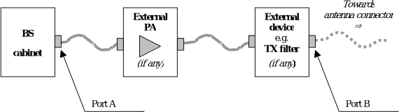
Figure 4.3.1-1: BS type 1-C transmitter interface
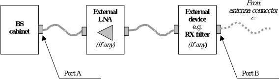
Figure 4.3.1-2: BS type 1-C receiver interface
4.3.2 BS type 1-H
For BS type 1-H , the requirements are defined for two points of reference, signified by radiated requirements and conducted requirements.
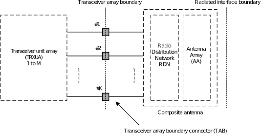
Figure 4.3.2-1: Radiated and conducted reference points for BS type 1-H
Radiated characteristics are defined over the air (OTA), where the operating band specific radiated interface is referred to as the Radiated Interface Boundary (RIB). Radiated requirements are also referred to as OTA requirements. The (spatial) characteristics in which the OTA requirements apply are detailed for each requirement.
Conducted characteristics are defined at individual or groups of TAB connectors at the transceiver array boundary , which is the conducted interface between the transceiver unit array and the composite antenna.
The transceiver unit array is part of the composite transceiver functionality generating modulated transmit signal structures and performing receiver combining and demodulation.
The transceiver unit array contains an implementation specific number of transmitter units and an implementation specific number of receiver units. Transmitter units and receiver units may be combined into transceiver units. The transmitter/receiver units have the ability to transmit/receive parallel independent modulated symbol streams.
The composite antenna contains a radio distribution network (RDN) and an antenna array. The RDN is a linear passive network which distributes the RF power generated by the transceiver unit array to the antenna array, and/or distributes the radio signals collected by the antenna array to the transceiver unit array, in an implementation specific way.
How a conducted requirement is applied to the transceiver array boundary is detailed in the respective requirement clause.
4.3.3 BS type 1-O and BS type 2-O
For BS type 1-O and BS type 2-O , the radiated characteristics are defined over the air (OTA), where the operating band specific radiated interface is referred to as the Radiated Interface Boundary (RIB). Radiated requirements are also referred to as OTA requirements. The (spatial) characteristics in which the OTA requirements apply are detailed for each requirement.
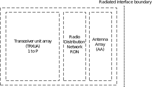
Figure 4.3.3-1: Radiated reference points for BS type 1-O and BS type 2-O
Co-location requirements are specified at the conducted interface of the co-location reference antenna , the c o-location reference antenna does not form part of the BS under test but is a means to provide OTA power levels which are representative of a co-located system, further defined in clause 4.9.
For a BS type 1-O the transceiver unit array must contain at least 8 transmitter units and at least 8 receiver units. Transmitter units and receiver units may be combined into transceiver units. The transmitter/receiver units have the ability to transmit/receive parallel independent modulated symbol streams.
4.4 Base station classes
The requirements in this specification apply to Wide Area Base Stations, Medium Range Base Stations and Local Area Base Stations unless otherwise stated. The associated deployment scenarios for each class are exactly the same for BS with and without connectors.
For BS type 1-O and 2-O, BS classes are defined as indicated below:
-
Wide Area Base Stations are characterised by requirements derived from Macro Cell scenarios with a BS to UE minimum distance along the ground equal to 35 m.
-
Medium Range Base Stations are characterised by requirements derived from Micro Cell scenarios with a BS to UE minimum distance along the ground equal to 5 m.
-
Local Area Base Stations are characterised by requirements derived from Pico Cell scenarios with a BS to UE minimum distance along the ground equal to 2 m.
NOTE: For BS type 2-O , Local Area Base stations are applicable also in Femto Cell scenarios.
For BS type 1-C and 1-H, BS classes are defined as indicated below:
-
Wide Area Base Stations are characterised by requirements derived from Macro Cell scenarios with a BS to UE minimum coupling loss equal to 70 dB.
-
Medium Range Base Stations are characterised by requirements derived from Micro Cell scenarios with a BS to UE minimum coupling loss equals to 53 dB.
-
Local Area Base Stations are characterised by requirements derived from Pico Cell scenarios with a BS to UE minimum coupling loss equal to 45 dB.
NOTE: Local Are Base stations are applicable also in Femto Cell scenarios.
For BS type 1-C, 1-H and 1-O, HAPS BS class is defined as indicated below:
-
HAPS Base Stations are characterised by requirements derived from High Altitude Platform scenarios with a BS to ground UE minimum distance of typically around 20km.
-
Unless otherwise stated, HAPS BS class would refer to Wide Area BS class, which is specified in clause 4.4.
For ATG BS type 1-C , 1-H and 1-O , ATG BS class is defined as below:
-
ATG Base Stations are characterized by requirements derived from ATG scenarios with a ground BS to air UE with typical vertical altitude of around 10,000m and take-off/landing altitudes down to 3000m.
-
Unless otherwise stated, ATG BS class would refer to Wide Area BS class, which is specified in clause 4.4.
4.5 Regional requirements
Some requirements in the present document may only apply in certain regions either as optional requirements, or as mandatory requirements set by local and regional regulation. It is normally not stated in the 3GPP specifications under what exact circumstances the regional requirements apply, since this is defined by local or regional regulation.
Table 4.5-1 lists all requirements in the present specification that may be applied differently in different regions.
Table 4.5-1: List of regional requirements
| Clause number | Requirement | Comments |
|---|---|---|
| 5.2 | Operating bands | Some NR operating bands may be applied regionally. |
| 6.2.1, 9.3.1 | Base station output power, OTA base station output power: | For Band n41 and n90 operation in Japan, additional output power limits shall be applied. |
| 6.2.4, 9.3.4 | Base station output power, OTA base station output power: Additional requirements | These requirements may be applied regionally as additional base station output power requirements. For operation with shared spectrum channel access, the BS may have to comply with the applicable BS power limits established regionally, when deployed in regions where those limits apply and under the conditions declared by the manufacturer. |
| 6.6.2, 9.7.2 | Occupied bandwidth, OTA occupied bandwidth | The requirement may be applied regionally. There may also be regional requirements to declare the occupied bandwidth according to the definition in present specification. |
| 6.6.3.3 | Adjacent Channel Leakage Power Ratio | For Band n41 and n90 operation in Japan, absolute ACLR limits shall be applied to the sum of the absolute ACLR power over all antenna connectors for BS type 1-C . |
| 6.6.4.2, 9.7.4.2 | Operating band unwanted emission, OTA operating band unwanted emissions | Category A or Category B operating band unwanted emissions limits may be applied regionally. In addition, for operation with shared spectrum channel access, the BS may have to comply with the applicable operating band unwanted emission limits established regionally, when deployed in regions where those limits apply and under the conditions declared by the manufacturer. |
| 6.6.4.2.5.1, 9.7.4.2.1.2 | Operating band unwanted emission, OTA operating band unwanted emissions: Limits in FCC Title 47 | The BS may have to comply with the additional requirements, when deployed in regions where those limits are applied, and under the conditions declared by the manufacturer. |
| 6.6.4.2.5.2, 9.7.4.2.1.1 | Operating band unwanted emission, OTA operating band unwanted emissions Protection of DTT | The BS operating in Band n20 may have to comply with the additional requirements for protection of DTT, when deployed in certain regions. |
| 6.6.4.3 | Operating band unwanted emissions | For Band n41 and n90 operation in Japan, the operating band unwanted emissions limits shall be applied to the sum of the emission power over all antenna connectors for BS type 1-C. |
| 6.6.5.2.1, 9.7.5.2 | Tx spurious emissions, OTA Tx spurious emissions | Category A or Category B spurious emission limits, as defined in ITU-R Recommendation SM.329 [2], may apply regionally. The emission limits for BS type 1-H and BS type 1-O specified as the basic limit + X (dB) are applicable, unless stated differently in regional regulation. In addition, for operation with shared spectrum channel access, the BS may have to comply with the applicable spurious emission limits established regionally, when deployed in regions where those limits apply and under the conditions declared by the manufacturer. |
| 6.6.5.2.3, 9.7.5.3.3 | Tx spurious emissions: additional requirements, OTA Tx spurious emissions: additional requirements | These requirements may be applied for the protection of system operating in frequency ranges other than the BS operating band . |
| 6.6.5.3 | Transmitter spurious emissions | For Band n41 and n90 operation in Japan, the sum of the spurious emissions over all antenna connectors for BS type 1-C shall not exceed the basic limits . |
| 6.7.2.1.1, 6.7.3.1.1 9.8.2 | Transmitter intermodulation, OTA transmitter intermodulation | Interfering signal positions that are partially or completely outside of any downlink operating band of the base station are not excluded from the requirement in Japan in Band n77, n78, n79. |
| 6.7.2.2, 6.7.3.3 | Transmitter intermodulation | For Band n41 and n90 operation in Japan, the BS may have to comply with the additional requirements, when deployed in certain regions. |
| 6.7.2.2, 6.7.3.3, 9.8.3 | Transmitter intermodulation, OTA transmitter intermodulation | For Band n79 operation in Japan, the BS shall comply with the additional requirements. |
| 6.7.2.2, 6.7.3.3, 9.8.3 | Transmitter intermodulation, OTA transmitter intermodulation | For Band n26 and n28 operation in Japan, the BS shall comply with the additional requirements when the narrowest channel bandwidth supported by the BS is 5MHz or wider. |
| 7.6.3 | Rx spurious emissions, | For Band n41 and n90 operation in Japan, the emission limits for BS type 1-C may apply to the sum of the emission power over all antenna connectors . |
| 7.6.4, 10.7.2 10.7.3 | Rx spurious emissions, OTA Rx spurious emissions | The emission limits for BS type 1-H and BS type 1-O specified as the basic limit + X (dB) are applicable, unless stated differently in regional regulation. Additional limits for BS type 2-O may apply regionally. |
| 9.7.4.3.4 | OTA operating band unwanted emissions | For Band n260 operation in Japan, the BS shall comply with the requirements. |
| 9.7.5.3.3 | OTA transmitter spurious emissions | For Band n259 operation in Japan, the BS shall comply with the requirements. |
| 10.7.3 | OTA Rx spurious emissions | For Band n259 and n260 operation in Japan, the BS shall comply with the requirements. |
4.6 Applicability of requirements
In table 4.6-1, the requirement applicability for each requirement set is defined. For each requirement, the applicable requirement clause in the specification is identified. Requirements not included in a requirement set is marked not applicable (NA).
Table 4.6-1: Requirement set applicability
| Requirement | Requirement set | Requirement set | Requirement set | Requirement set |
|---|---|---|---|---|
| BS type 1-C | BS type 1-H | BS type 1-O | BS type 2-O | |
| BS output power | 6.2 | 6.2 | ||
| Output power dynamics | 6.3 | 6.3 | ||
| Transmit ON/OFF power | 6.4 | 6.4 | ||
| Transmitted signal quality | 6.5 | 6.5 | ||
| Occupied bandwidth | 6.6.2 | 6.6.2 | ||
| ACLR | 6.6.3 | 6.6.3 | ||
| Operating band unwanted emissions | 6.6.4 | 6.6.4 | ||
| Transmitter spurious emissions | 6.6.5 | 6.6.5 | ||
| Transmitter intermodulation | 6.7 | 6.7 | NA | NA |
| Reference sensitivity level | 7.2 | 7.2 | ||
| Dynamic range | 7.3 | 7.3 | ||
| In-band selectivity and blocking | 7.4 | 7.4 | ||
| Out-of-band blocking | 7.5 | 7.5 | ||
| Receiver spurious emissions | 7.6 | 7.6 | ||
| Receiver intermodulation | 7.7 | 7.7 | ||
| In-channel selectivity | 7.8 | 7.8 | ||
| Performance requirements | 8 | 8 | ||
| Radiated transmit power | 9.2 | 9.2 | 9.2 | |
| OTA base station output power | 9.3 | 9.3 | ||
| OTA output power dynamics | 9.4 | 9.4 | ||
| OTA transmit ON/OFF power | 9.5 | 9.5 | ||
| OTA transmitted signal quality | 9.6 | 9.6 | ||
| OTA occupied bandwidth | 9.7.2 | 9.7.2 | ||
| OTA ACLR | NA | 9.7.3 | 9.7.3 | |
| OTA operating band unwanted emissions | 9.7.4 | 9.7.4 | ||
| OTA transmitter spurious emission | 9.7.5 | 9.7.5 | ||
| OTA transmitter intermodulation | 9.8 | NA | ||
| OTA spatial emission | 9.9 | 9.9 | NA | |
| OTA sensitivity | 10.2 | 10.2 | NA | |
| OTA reference sensitivity level | NA | 10.3 | 10.3 | |
| OTA dynamic range | 10.4 | NA | ||
| OTA in-band selectivity and blocking | 10.5 | 10.5 | ||
| OTA out-of-band blocking | NA | 10.6 | 10.6 | |
| OTA receiver spurious emission | 10.7 | 10.7 | ||
| OTA receiver intermodulation | 10.8 | 10.8 | ||
| OTA in-channel selectivity | 10.9 | 10.9 | ||
| Radiated performance requirements | 11 | 11 |
4.7 Requirements for contiguous and non-contiguous spectrum
A spectrum allocation where a BS operates can either be contiguous or non-contiguous. Unless otherwise stated, the requirements in the present specification apply for BS configured for both contiguous spectrum operation and non-contiguous spectrum operation.
For BS operation in non-contiguous spectrum , some requirements apply both at the Base Station RF Bandwidth edges and inside the sub-block gaps . For each such requirement, it is stated how the limits apply relative to the Base Station RF Bandwidth edges and the sub-block edges respectively.
4.8 Requirements for BS capable of multi-band operation
For multi-band connector or multi-band RIB , the RF requirements in clause 6, 7, 9 and 10 apply separately to each supported operating band unless otherwise stated. For some requirements, it is explicitly stated that specific additions or exclusions to the requirement apply at multi-band connector(s) , and multi-band RIB(s) as detailed in the requirement clause. For BS capable of multi-band operation, various structures in terms of combinations of different transmitter and receiver implementations (multi-band or single band) with mapping of transceivers to one or more antenna connectors for BS type 1-C or TAB connectors for BS type 1-H in different ways are possible. For multi-band connector(s) the exclusions or provisions for multi-band apply. For single-band connector(s) , the following applies:
-
Single-band transmitter spurious emissions, operating band unwanted emissions, ACLR, transmitter intermodulation and receiver spurious emissions requirements apply to this connector that is mapped to single-band. In case there are carrier(s) transmitted simultaneously in another supported operating band in common active RF components, when the RF signals of these antenna connectors cover the same geographical area, the frequency range of the Base Station RF bandwidth in the other supported band to this antenna connector should be excluded from the unwanted emission requirements.
-
If the BS is configured for single-band operation, single-band requirements shall apply to this connector configured for single-band operation and no exclusions or provisions for multi-band capable BS are applicable. Single-band requirements are tested separately at the connector configured for single-band operation, with all other antenna connectors terminated.
A BS type 1-H may be capable of supporting operation in multiple operating bands with one of the following implementations of TAB connectors in the transceiver array boundary :
-
All TAB connectors are single-band connectors .
-
Different sets of single-band connectors support different operating bands , but each TAB connector supports only operation in one single operating band .
-
Sets of single-band connectors support operation in multiple operating bands with some single-band connectors supporting more than one operating band .
-
All TAB connectors are multi-band connectors .
-
A combination of single-band sets and multi-band sets of TAB connectors provides support of the type BS type 1-H capability of operation in multiple operating bands .
Unless otherwise stated all requirements specified for an operating band apply only to the set of TAB connectors supporting that operating band .
In the case of an operating band being supported only by single-band connectors in a TAB connector TX min cell group or a TAB connector RX min cell group , single-band requirements apply to that set of TAB connectors .
In the case of an operating band being supported only by multi-band connector s supporting the same operating band combination in a TAB connector TX min cell group or a TAB connector RX min cell group , multi-band requirements apply to that set of TAB connectors .
The case of an operating band being supported by both multi-band connectors and single-band connectors in a TAB connector TX min cell group or a TAB connector RX min cell group is not covered by the present release of this specification.
The case of an operating band being supported by multi-band connectors which are not all supporting the same operating band combination in a TAB connector TX min cell group or a TAB connector RX min cell group is not covered by the present release of this specification.
BS type 1-O may be capable of supporting operation in multiple operating bands with one of the following implementations at the radiated interface boundary :
-
All RIBs are single-band RIBs .
-
All RIBs are multi-band RIBs .
-
A combination of single-band RIBs and multi-band RIBs provides support of the BS type 1-O capability of operation in multiple operating bands .
For multi-band connectors and multi-band RIBs supporting the bands for TDD, the RF requirements in the present specification assume no simultaneous uplink and downlink occur between the bands.
The RF requirements for multi-band connectors and multi-band RIBs supporting bands for both FDD and TDD are not covered by the present release of this specification.
4.9 OTA co-location with other base stations
Co-location requirements are requirements which are based on assuming the BS type 1-O is co-located with another BS of the same base station class, they ensure that both co-located systems can operate with minimal degradation to each other.
Unwanted emission and out of band blocking co-location requirements are optional requirements based on declaration. TX OFF and TX IMD are mandatory requirements and have the form of a co-location requirement as it represents the worst-case scenario of all the interference cases.
NOTE: Due to the low level of the unwanted emissions for the spurious emissions and TX OFF level co-location is the most suitable method to show conformance.
The co-location reference antenna shall be a single column passive antenna which has the same vertical radiating dimension (h), frequency range, polarization, as the composite antenna of the BS type 1-O and nominal 65° horizontal half-power beamwidth (suitable for 3-sector deployment) and is placed at a distance d from the edge of the BS type 1-O , as shown in figure 4.9-1.
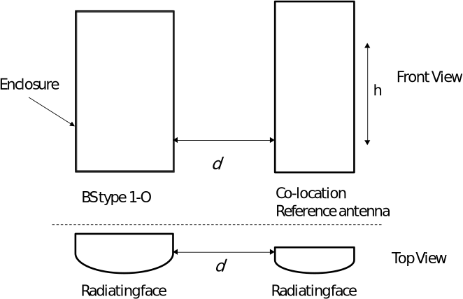
Figure 4.9-1: Illustration of BS type 1-O enclosure and co-location reference antenna
Edge-to-edge separation d between the BS type 1-O and the co-location reference antenna shall be set to 0.1 m.
The BS type 1-O and the co-location reference antenna shall be aligned in a common plane perpendicular to the mechanical bore-sight direction, as shown in figure 4.9-1.
The co-location reference antenna and the BS type 1-O can have different width.
The vertical radiating regions of the co-location reference antenna and the BS type 1-O composite antenna shall be aligned.
For co-location requirements where the frequency range of the signal at the co-location reference antenna is different from the BS type 1-O , a co-location reference antenna suitable for the frequency stated in the requirement is assumed.
OTA co-location requirements are based on the power at the conducted interface of a co-location reference antenna , depending on the requirement this interface is either an input or an output. For BS type 1-O with dual polarization the co-location reference antenna has two conducted interfaces each representing one polarization.
5 Operating bands and channel arrangement
5.1 General
The channel arrangements presented in this clause are based on the operating bands and BS channel bandwidths defined in the present release of specifications.
NOTE: Other operating bands and BS channel bandwidth s may be considered in future releases.
Requirements throughout the RF specifications are in many cases defined separately for different frequency ranges (FR). The frequency ranges in which NR can operate according to the present version of the specification are identified as described in table 5.1-1. Whenever FR2 is referred, both FR2-1 and FR2-2 frequency sub-ranges shall be applied, unless otherwise stated.
Table 5.1-1: Definition of frequency ranges
| Frequency range designation | Frequency range designation | Corresponding frequency range |
|---|---|---|
| FR1 | FR1 | 410 MHz – 7125 MHz |
| FR2 | FR2-1 | 24250 MHz – 52600 MHz |
| FR2-2 | 52600 MHz – 71000 MHz |
5.2 Operating bands
NR is designed to operate in the operating bands defined in table 5.2-1 and 5.2-2.
NR operating band n1, n2, n3, n5, n7, n8, n20, n25, n26, n28, n34, n38, n39, n41, n67, n85 and n90 which are defined in Table 5.2-1, can be applied for HAPS operation.
NOTE: For HAPS operation, the UL and DL frequency ranges are identifed in Nos. 5.312B, 5.314A, 5.388A and 5.409A and under the conditions specified in Resolutions 213, 218 and 221 in the ITU Radio Regulations [28].
NR operating bands n1, n3, n34, n39, n41, n78, n79, which are defined in Table 5.2-1, can be applied for ATG operation.
NB-IoT is designed to operate in the NR operating bands n1, n2, n3, n5, n7, n8, n12, n13, n14, n18, n20, n25, n26, n28, n31, n41, n65, n66, n70, n71, n72, n74, n85, n87, n88, n90, n106 which are defined in Table 5.2-1.
Subband non-overlapping full duplex (SBFD) is designed to operate in NR TDD operating bands in FR1 which are defined in Table 5.2-1 except bands n34, n46, n51, n53, n54, n96, n101 and n102, and NR operating bands in FR2-1 which are defined in Table 5.2-2 except band n263.
LP-WUS is designed to operate in the NR operating bands defined in Table 5.2-1 for FR1 and Table 5.2-2 for FR2-1, excluding SUL and SDL bands as well as bands n46, n47, n96, and n102.
Table 5.2-1: NR operating bands in FR1
| NR operating band | Uplink (UL) operating band BS receive / UE transmit F UL,low – F UL,high (MHz) | Downlink (DL) operating band BS transmit / UE receive F DL,low – F DL,high (MHz) | Duplex mode | Notes |
|---|---|---|---|---|
| n1 | 1920 – 1980 | 2110 – 2170 | FDD | |
| n2 | 1850 – 1910 | 1930 – 1990 | FDD | |
| n3 | 1710 – 1785 | 1805 – 1880 | FDD | |
| n5 | 824 – 849 | 869 – 894 | FDD | |
| n7 | 2500 – 2570 | 2620 – 2690 | FDD | |
| n8 | 880 – 915 | 925 – 960 | FDD | |
| n12 | 699 – 716 | 729 – 746 | FDD | |
| n13 | 777 – 787 | 746 – 756 | FDD | |
| n14 | 788 – 798 | 758 – 768 | FDD | |
| n18 | 815 – 830 | 860 – 875 | FDD | |
| n20 | 832 – 862 | 791 – 821 | FDD | |
| n24 | 1626.5 – 1660.5 | 1525 – 1559 | FDD | Note 7 |
| n25 | 1850 – 1915 | 1930 – 1995 | FDD | |
| n26 | 814 – 849 | 859 – 894 | FDD | |
| n28 | 703 – 748 | 758 – 803 | FDD | |
| n29 | N/A | 717 – 728 | SDL | |
| n30 | 2305 – 2315 | 2350 – 2360 | FDD | |
| n31 | 452.5 – 457.5 | 462.5 – 467.5 | FDD | |
| n34 | 2010 – 2025 | 2010 – 2025 | TDD | Note 12 |
| n38 | 2570 – 2620 | 2570 – 2620 | TDD | |
| n39 | 1880 – 1920 | 1880 – 1920 | TDD | |
| n40 | 2300 – 2400 | 2300 – 2400 | TDD | |
| n41 | 2496 – 2690 | 2496 – 2690 | TDD | |
| n46 | 5150 – 5925 | 5150 – 5925 | TDD | Note 3, Note 12 |
| n48 | 3550 – 3700 | 3550 – 3700 | TDD | |
| n50 | 1432 – 1517 | 1432 – 1517 | TDD | |
| n51 | 1427 – 1432 | 1427 – 1432 | TDD | Note 12 |
| n53 | 2483.5 – 2495 | 2483.5 – 2495 | TDD | Note 12 |
| n54 | 1670 – 1675 | 1670 – 1675 | TDD | Note 12 |
| n65 | 1920 – 2010 | 2110 – 2200 | FDD | |
| n66 | 1710 – 1780 | 2110 – 2200 | FDD | |
| n67 | N/A | 738 – 758 | SDL | |
| n68 | 698 – 728 | 753 – 783 | FDD | |
| n70 | 1695 – 1710 | 1995 – 2020 | FDD | |
| n71 | 663 – 698 | 617 – 652 | FDD | |
| n72 | 451 – 456 | 461 – 466 | FDD | |
| n74 | 1427 – 1470 | 1475 – 1518 | FDD | |
| n75 | N/A | 1432 – 1517 | SDL | |
| n76 | N/A | 1427 – 1432 | SDL | |
| n77 | 3300 – 4200 | 3300 – 4200 | TDD | Note 11 |
| n78 | 3300 – 3800 | 3300 – 3800 | TDD | |
| n79 | 4400 – 5000 | 4400 – 5000 | TDD | |
| n80 | 1710 – 1785 | N/A | SUL | |
| n81 | 880 – 915 | N/A | SUL | |
| n82 | 832 – 862 | N/A | SUL | |
| n83 | 703 – 748 | N/A | SUL | |
| n84 | 1920 – 1980 | N/A | SUL | |
| n85 | 698 – 716 | 728 – 746 | FDD | |
| n86 | 1710 – 1780 | N/A | SUL | |
| n87 | 410 - 415 | 420 – 425 | FDD | |
| n88 | 412 - 417 | 422 - 427 | FDD | |
| n89 | 824 – 849 | N/A | SUL | |
| n90 | 2496 – 2690 | 2496 – 2690 | TDD | |
| n91 | 832 – 862 | 1427 – 1432 | FDD | Note 2 |
| n92 | 832 – 862 | 1432 – 1517 | FDD | Note 2 |
| n93 | 880 – 915 | 1427 – 1432 | FDD | Note 2 |
| n94 | 880 – 915 | 1432 – 1517 | FDD | Note 2 |
| n95 | 2010 – 2025 | N/A | SUL | Note 1 |
| n96 | 5925 – 7125 | 5925 – 7125 | TDD | Note 3, Note 4, Note 12 |
| n97 | 2300 – 2400 | N/A | SUL | Note 5 |
| n98 | 1880 – 1920 | N/A | SUL | Note 5 |
| n99 | 1626.5 – 1660.5 | N/A | SUL | Note 6 |
| n100 | 874.4 – 880 | 919.4 – 925 | FDD | Note 10 |
| n101 | 1900 – 1910 | 1900 – 1910 | TDD | Note 10, Note 12 |
| n102 | 5925 – 6425 | 5925 – 6425 | TDD | Note 3, Note 4, Note 12 |
| n104 | 6425 – 7125 | 6425 – 7125 | TDD | |
| n105 | 663 – 703 | 612 – 652 | FDD | |
| n106 | 896 – 901 | 935 – 940 | FDD | |
| n109 | 703 – 733 | 1432 – 1517 | FDD | Note 2 |
| n110 | 1390 - 1395 | 1432 - 1435 | FDD | |
| n115 | 1427.9 MHz – 1462.9 MHz | 1475.9 MHz – 1510.9 MHz | FDD | Note 13 |
| NOTE 1: This band is applicable in China only. NOTE 2: Variable duplex operation does not enable dynamic variable duplex configuration by the network, and is used such that DL and UL frequency ranges are supported independently in any valid frequency range for the band. NOTE 3: This band is restricted to operation with shared spectrum channel access as defined in TS 37.213 [20]. NOTE 4: This band is applicable only in countries/regions designating this band for shared-spectrum access use subject to country-specific conditions. NOTE 5: The requirements for this band are applicable only where no other NR or E-UTRA TDD operating band(s) are used within the frequency range of this band in the same geographical area. For scenarios where other NR or E-UTRA TDD operating band(s) are used within the frequency range of this band in the same geographical area, special co-existence requirements may apply that are not covered by the 3GPP specifications. NOTE 6: UL operation is restricted to 1627.5 – 1637.5 MHz and 1646.5 – 1656.5 MHz per FCC Order DA 20-48 [25]. NOTE 7: DL operation is restricted to 1526-1536 MHz frequency range. UL operation is restricted to 1627.5 – 1637.5 MHz and 1646.5 – 1656.5 MHz per FCC Order 20-51 [24]. NOTE 8: Void NOTE 9: Operating band n200 is a reserved value. NOTE 10: This band is applicable to CEPT countries subject to ECC Decision (20)02 [21], for the RMR application. NOTE 11: In the USA this band is restricted to 3450 – 3550 MHz and 3700 – 3980 MHz. In Canada this band is restricted to 3450 – 3650 MHz and 3650 – 3980 MHz. NOTE 12: This TDD band is not applicable to SBFD operation. NOTE13: The new NR band is defined according to Japanese regulations. |
Table 5.2-2: NR operating bands in FR2
| NR operating band | Uplink (UL) and Downlink (DL) operating band BS transmit/receive UE transmit/receive F UL,low – F UL,high F DL,low – F DL,high (MHz) | Duplex mode | Notes |
|---|---|---|---|
| n257 | 26500 – 29500 | TDD | |
| n258 | 24250 – 27500 | TDD | |
| n259 | 39500 – 43500 | TDD | |
| n260 | 37000 – 40000 | TDD | |
| n261 | 27500 – 28350 | TDD | |
| n262 | 47200 – 48200 | TDD | |
| n263 | 57000 – 71000 | TDD | Note 1 |
| NOTE 1: This TDD band is not applicable to SBFD operation. | NOTE 1: This TDD band is not applicable to SBFD operation. | NOTE 1: This TDD band is not applicable to SBFD operation. | NOTE 1: This TDD band is not applicable to SBFD operation. |
5.3 BS channel bandwidth
5.3.1 General
The BS channel bandwidth supports a single NR RF carrier in the uplink or downlink at the Base Station. Different UE channel bandwidths may be supported within the same spectrum for transmitting to and receiving from UEs connected to the BS. The placement of the UE channel bandwidth is flexible but can only be completely within the BS channel bandwidth . The BS shall be able to transmit to and/or receive from one or more UE bandwidth parts that are smaller than or equal to the number of carrier resource blocks on the RF carrier, in any part of the carrier resource blocks.
The relationship between the channel bandwidth, the guardband and the transmission bandwidth configuration is shown in figure 5.3.1-1.
Figure 5.3.1-1: Definition of channel bandwidth and transmission bandwidth configuration for one NR channel
For SBFD-capable BS, the transmission bandwidth configurations for SBFD DL subband(s) and UL subbands are defined over the carrier configured for SBFD operation. The relationship between the channel bandwidth, the guardband and the transmission bandwidth configuration for SBFD DL subband(s) and UL subband is shown in figures 5.3.1-2, 5.3.1-3 and 5.3.1-4, respectively for SBFD DUD, DU and UD operations.
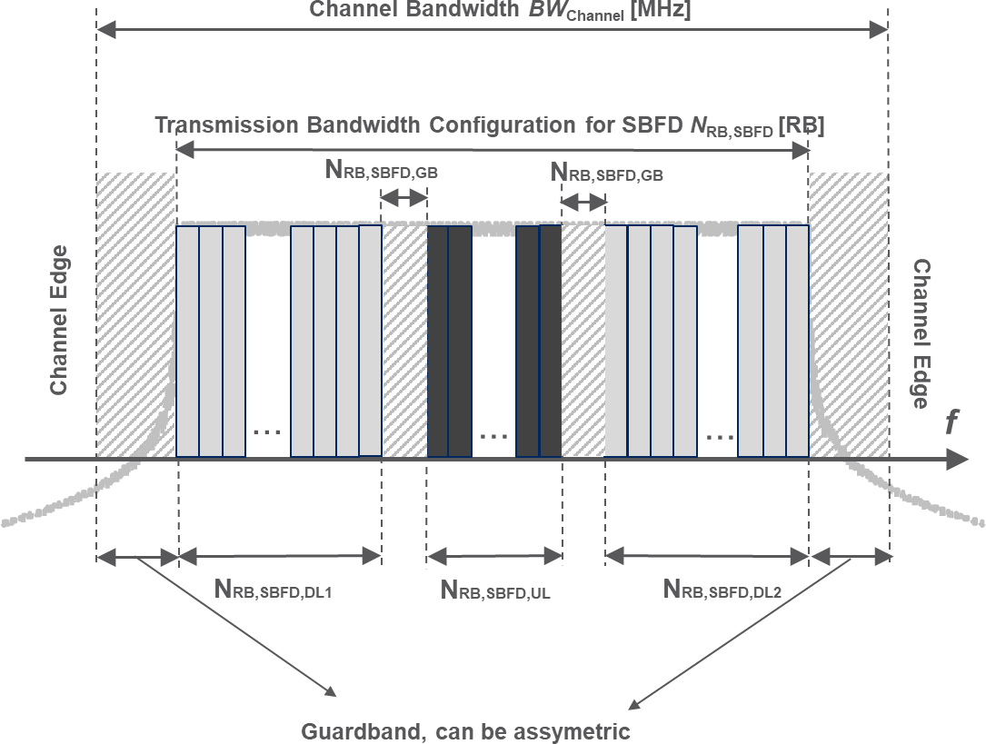
Figure 5.3.1-2: Definition of channel bandwidth and transmission bandwidth configuration for SBFD DUD operation
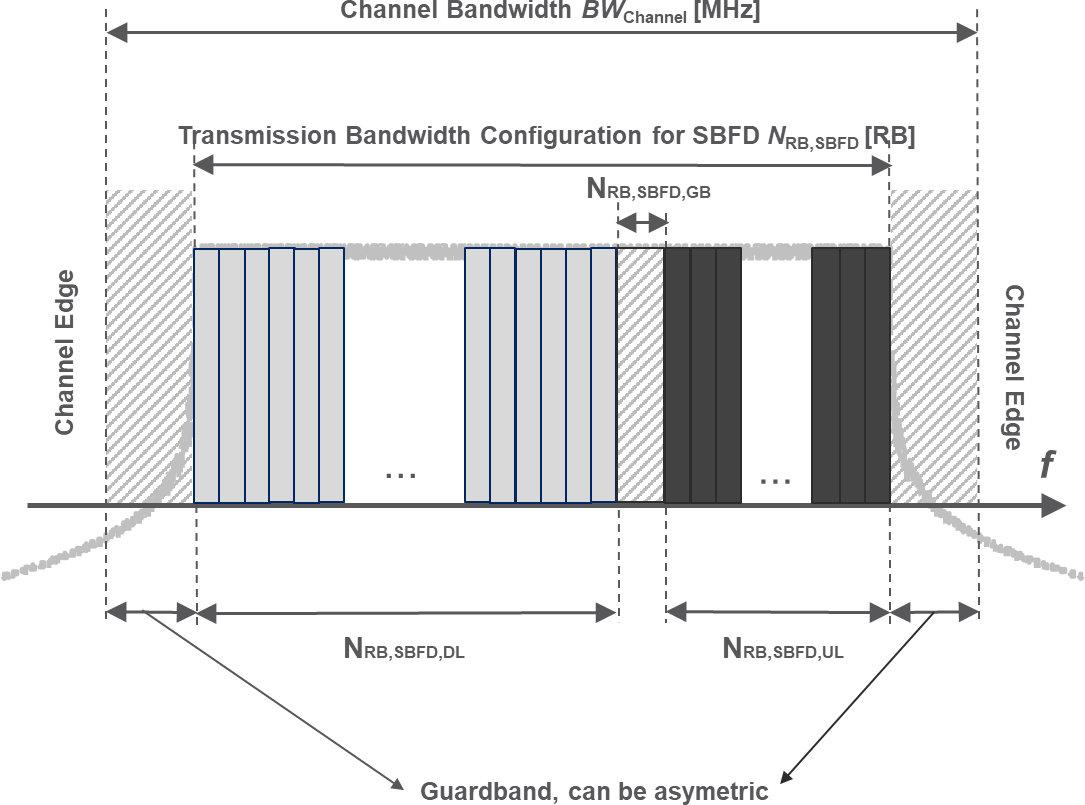
Figure 5.3.1-3: Definition of channel bandwidth and transmission bandwidth configuration for SBFD DU operation
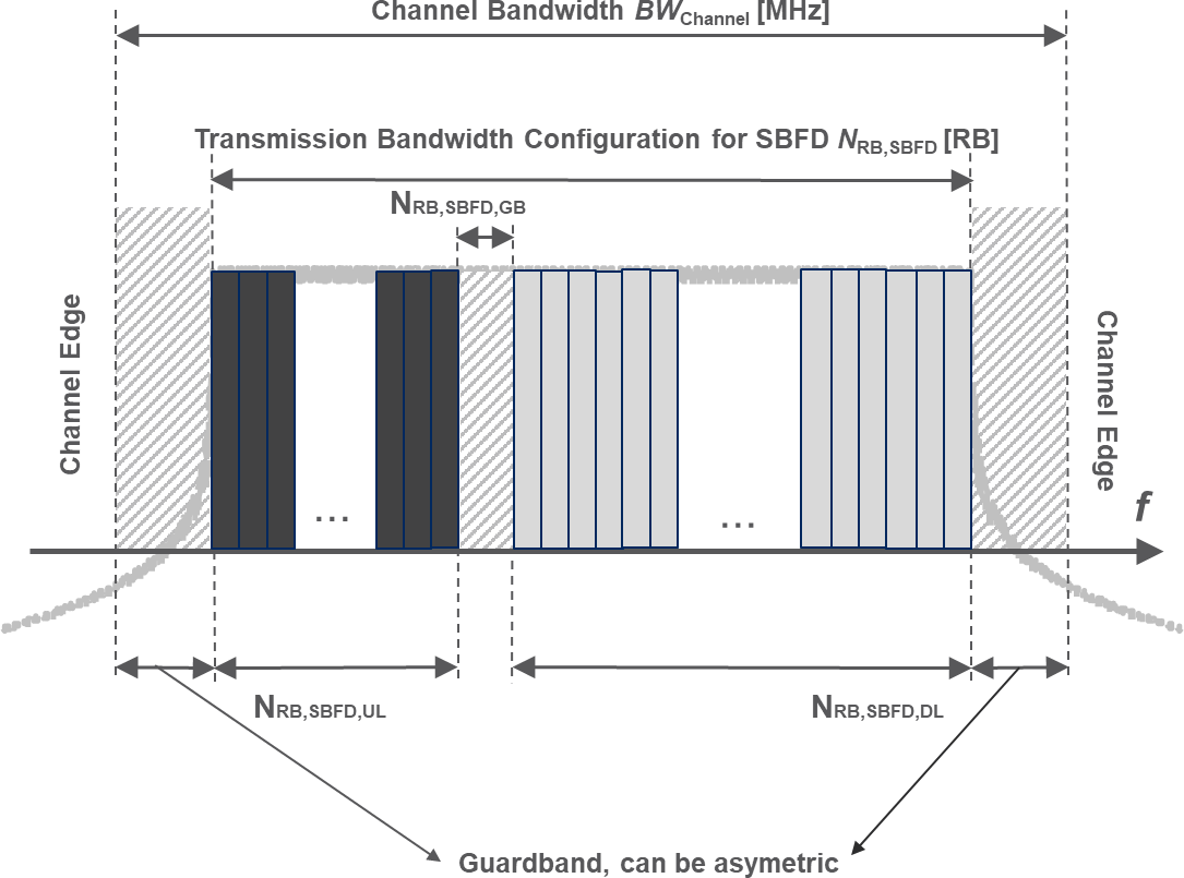
Figure 5.3.1-4: Definition of channel bandwidth and transmission bandwidth configuration for SBFD UD operation
5.3.2 Transmission bandwidth configuration
The transmission bandwidth configuration N RB for each BS channel bandwidth and subcarrier spacing is specified in table 5.3.2.-1 for FR1 and table 5.3.2-2 for FR2.
Table 5.3.2-1: Transmission bandwidth configuration N RB for FR1
| SCS (kHz) | 3 MHz | 5 MHz | 7 MHz | 10 MHz | 15 MHz | 20 MHz | 25 MHz | 30 MHz | 35 MHz | 40 MHz | 45 MHz | 50 MHz | 60 MHz | 70 MHz | 80 MHz | 90 MHz | 100 MHz |
|---|---|---|---|---|---|---|---|---|---|---|---|---|---|---|---|---|---|
| N RB | N RB | N RB | N RB | N RB | N RB | N RB | N RB | N RB | N RB | N RB | N RB | N RB | N RB | N RB | N RB | N RB | |
| 15 | 15 | 25 | 35 | 52 | 79 | 106 | 133 | 160 | 188 | 216 | 242 | 270 | N/A | N/A | N/A | N/A | N/A |
| 30 | N/A | 11 | N/A | 24 | 38 | 51 | 65 | 78 | 92 | 106 | 119 | 133 | 162 | 189 | 217 | 245 | 273 |
| 60 | N/A | N/A | N/A | 11 | 18 | 24 | 31 | 38 | 44 | 51 | 58 | 65 | 79 | 93 | 107 | 121 | 135 |
| Note: In FR1 bands applicable to SBFD operation, the BS channel bandwidth for SBFD operation shall be no less than 40MHz and no less than 20MHz for band n39. | Note: In FR1 bands applicable to SBFD operation, the BS channel bandwidth for SBFD operation shall be no less than 40MHz and no less than 20MHz for band n39. | Note: In FR1 bands applicable to SBFD operation, the BS channel bandwidth for SBFD operation shall be no less than 40MHz and no less than 20MHz for band n39. | Note: In FR1 bands applicable to SBFD operation, the BS channel bandwidth for SBFD operation shall be no less than 40MHz and no less than 20MHz for band n39. | Note: In FR1 bands applicable to SBFD operation, the BS channel bandwidth for SBFD operation shall be no less than 40MHz and no less than 20MHz for band n39. | Note: In FR1 bands applicable to SBFD operation, the BS channel bandwidth for SBFD operation shall be no less than 40MHz and no less than 20MHz for band n39. | Note: In FR1 bands applicable to SBFD operation, the BS channel bandwidth for SBFD operation shall be no less than 40MHz and no less than 20MHz for band n39. | Note: In FR1 bands applicable to SBFD operation, the BS channel bandwidth for SBFD operation shall be no less than 40MHz and no less than 20MHz for band n39. | Note: In FR1 bands applicable to SBFD operation, the BS channel bandwidth for SBFD operation shall be no less than 40MHz and no less than 20MHz for band n39. | Note: In FR1 bands applicable to SBFD operation, the BS channel bandwidth for SBFD operation shall be no less than 40MHz and no less than 20MHz for band n39. | Note: In FR1 bands applicable to SBFD operation, the BS channel bandwidth for SBFD operation shall be no less than 40MHz and no less than 20MHz for band n39. | Note: In FR1 bands applicable to SBFD operation, the BS channel bandwidth for SBFD operation shall be no less than 40MHz and no less than 20MHz for band n39. | Note: In FR1 bands applicable to SBFD operation, the BS channel bandwidth for SBFD operation shall be no less than 40MHz and no less than 20MHz for band n39. | Note: In FR1 bands applicable to SBFD operation, the BS channel bandwidth for SBFD operation shall be no less than 40MHz and no less than 20MHz for band n39. | Note: In FR1 bands applicable to SBFD operation, the BS channel bandwidth for SBFD operation shall be no less than 40MHz and no less than 20MHz for band n39. | Note: In FR1 bands applicable to SBFD operation, the BS channel bandwidth for SBFD operation shall be no less than 40MHz and no less than 20MHz for band n39. | Note: In FR1 bands applicable to SBFD operation, the BS channel bandwidth for SBFD operation shall be no less than 40MHz and no less than 20MHz for band n39. | Note: In FR1 bands applicable to SBFD operation, the BS channel bandwidth for SBFD operation shall be no less than 40MHz and no less than 20MHz for band n39. |
Table 5.3.2-2: Transmission bandwidth configuration N RB for FR2-1
| SCS (kHz) | 50 MHz | 100 MHz | 200 MHz | 400 MHz |
|---|---|---|---|---|
| N RB | N RB | N RB | N RB | |
| 60 | 66 | 132 | 264 | N/A |
| 120 | 32 | 66 | 132 | 264 |
| Note: The BS channel bandwidth for SBFD operation shall be no less than 100MHz. | Note: The BS channel bandwidth for SBFD operation shall be no less than 100MHz. | Note: The BS channel bandwidth for SBFD operation shall be no less than 100MHz. | Note: The BS channel bandwidth for SBFD operation shall be no less than 100MHz. | Note: The BS channel bandwidth for SBFD operation shall be no less than 100MHz. |
Table 5.3.2-3: Transmission bandwidth configuration N RB for FR2-2
| SCS (kHz) | 100 MHz | 400 MHz | 800 MHz | 1600 MHz | 2000 MHz |
|---|---|---|---|---|---|
| N RB | N RB | N RB | N RB | N RB | |
| 120 | 66 | 264 | N/A | N/A | N/A |
| 480 | N/A | 66 | 124 | 248 | N/A |
| 960 | N/A | 33 | 62 | 124 | 148 |
NOTE: All Tx and Rx requirements are defined based on transmission bandwidth configuration specified in table 5.3.2-1 for FR1 and table 5.3.2-2 and table 5.3.2-3 for FR2.
The transmission bandwidth configuration for NB-IoT is specified in TS 36.104 [13] clause 5.6.
For SBFD operation, the transmission bandwidth configuration for SBFD UL subband N RB,SBFD,UL shall be configured according to the values provided for BS transmission bandwidth configuration N RB corresponding to bandwidth no less than 10MHz in Table 5.3.2-1 for FR1, and N RB in Table 5.3.2-2 for FR2-1. Transmission bandwidth configuration for SBFD DL subband in SBFD (i.e., N RB,SBFD,DL for SBFD DU or UD operation, and N RB,SBFD,DL,1 and N RB,SBFD,DL,2 for SBFD DUD operation) and guardband between SBFD UL subband and DL subband shall be configured by SBFD-capable BS. For SBFD DUD operation, N RB,SBFD,DL,1 and N RB,SBFD,DL,2 shall have the same size or different sizes by only 1RB.
For LP-WUS operation, the LP-WUS occupies fixed 11 RBs for all available NR CBW in FR1 and FR2-1. The LP-WUS is embedded within the NR BS channel and is flexibly positioned, and provided alignment with the NR PRB grid is maintained.
The transmission bandwidth configuration N RB,LP-WUS for LP-WUS within each NR BS channel bandwidth and subcarrier spacing for FR1 is specified in Table 5.3.2-4.
Table 5.3.2-4: Transmission bandwidth configuration N RB,LP-WUS for LP-WUS for FR1
| SCS (kHz) | 3 MHz | 5 MHz | 7 MHz | 10 MHz | 15 MHz | 20 MHz | 25 MHz | 30 MHz | 35 MHz | 40 MHz | 45 MHz | 50 MHz | 60 MHz | 70 MHz | 80 MHz | 90 MHz | 100 MHz |
|---|---|---|---|---|---|---|---|---|---|---|---|---|---|---|---|---|---|
| N RB, LP-WUS | N RB, LP-WUS | N RB, LP-WUS | N RB, LP-WUS | N RB, LP-WUS | N RB, LP-WUS | N RB, LP-WUS | N RB, LP-WUS | N RB, LP-WUS | N RB, LP-WUS | N RB, LP-WUS | N RB, LP-WUS | N RB, LP-WUS | N RB, LP-WUS | N RB, LP-WUS | N RB, LP-WUS | N RB, LP-WUS | |
| 15 | 11 | 11 | 11 | 11 | 11 | 11 | 11 | 11 | 11 | 11 | 11 | 11 | N/A | N/A | N/A | N/A | N/A |
| 30 | N/A | 11 | N/A | 11 | 11 | 11 | 11 | 11 | 11 | 11 | 11 | 11 | 11 | 11 | 11 | 11 | 11 |
| 60 | N/A | N/A | N/A | N/A | N/A | N/A | N/A | N/A | N/A | N/A | N/A | N/A | N/A | N/A | N/A | N/A | N/A |
The transmission bandwidth configuration N RB,LP-WUS for LP-WUS within each NR BS channel bandwidth and subcarrier spacing for FR2-1 is specified in Table 5.3.2-5.
Table 5.3.2-5: Transmission bandwidth configuration N RB,LP-WUS for LP-WUS for FR2-1
| SCS (kHz) | 50 MHz | 100 MHz | 200 MHz | 400 MHz |
|---|---|---|---|---|
| N RB,LP-WUS | N RB,LP-WUS | N RB,LP-WUS | N RB,LP-WUS | |
| 60 | 11 | 11 | 11 | N/A |
| 120 | 11 | 11 | 11 | 11 |
5.3.3 Minimum guardband and transmission bandwidth configuration
The minimum guardband for each BS channel bandwidth and SCS is specified in table 5.3.3-1 for FR1 and in table 5.3.3-2 and table 5.3.3-2a for FR2.
Table 5.3.3-1: Minimum guardband (kHz) (FR1)
| SCS (kHz) | 3 MHz | 5 MHz | 7 MHz | 10 MHz | 15 MHz | 20 MHz | 25 MHz | 30 MHz | 35 MHz | 40 MHz | 45 MHz | 50 MHz | 60 MHz | 70 MHz | 80 MHz | 90 MHz | 100 MHz |
|---|---|---|---|---|---|---|---|---|---|---|---|---|---|---|---|---|---|
| 15 | 142.5 | 242.5 | 342.5 | 312.5 | 382.5 | 452.5 | 522.5 | 592.5 | 572.5 | 552.5 | 712.5 | 692.5 | N/A | N/A | N/A | N/A | N/A |
| 30 | N/A | 505 | N/A | 665 | 645 | 805 | 785 | 945 | 925 | 905 | 1065 | 1045 | 825 | 965 | 925 | 885 | 845 |
| 60 | N/A | N/A | N/A | 1010 | 990 | 1330 | 1310 | 1290 | 1630 | 1610 | 1590 | 1570 | 1530 | 1490 | 1450 | 1410 | 1370 |
Table 5.3.3-2: Minimum guardband (kHz) (FR2-1)
| SCS (kHz) | 50 MHz | 100 MHz | 200 MHz | 400 MHz |
|---|---|---|---|---|
| 60 | 1210 | 2450 | 4930 | N/A |
| 120 | 1900 | 2420 | 4900 | 9860 |
Table 5.3.3-2a: Minimum guardband (kHz) (FR2-2)
| SCS (kHz) | 100 MHz | 400 MHz | 800 MHz | 1600 MHz | 2000 MHz |
|---|---|---|---|---|---|
| 120 | 2420 | 9860 | N/A | N/A | N/A |
| 480 | N/A | 9680 | 42640 | 85520 | N/A |
| 960 | N/A | 9440 | [42400] | 85280 | 147040 |
The minimum guardband of SCS 240 kHz SS/PBCH block for each BS channel bandwidth is specified in table 5.3.3-3 for FR2.
Table 5.3.3-3: Minimum guardband (kHz) of SCS 240 kHz SS/PBCH block (FR2)
| SCS (kHz) | 100 MHz | 200 MHz | 400 MHz |
|---|---|---|---|
| 240 | 3800 | 7720 | 15560 |
NOTE: The minimum guardband in Table 5.3.3-3 is applicable only when the SCS 240 kHz SS/PBCH block is placed adjacent to the edge of the BS channel bandwidth within which the SS/PBCH block is located.
The number of RBs configured in any BS channel bandwidth shall ensure that the minimum guardband specified in this clause is met.

Figure 5.3.3-1: BS PRB utilization
In the case that multiple numerologies are multiplexed in the same symbol, the minimum guardband on each side of the carrier is the guardband applied at the configured BS channel bandwidth for the numerology that is transmitted/received immediately adjacent to the guard band.
For FR1, if multiple numerologies are multiplexed in the same symbol and the BS channel bandwidth is >50 MHz, the guardband applied adjacent to 15 kHz SCS shall be the same as the guardband defined for 30 kHz SCS for the same BS channel bandwidth .
For FR2, if multiple numerologies are multiplexed in the same symbol and the BS channel bandwidth is >200 MHz, the guardband applied adjacent to 60 kHz SCS shall be the same as the guardband defined for 120 kHz SCS for the same BS channel bandwidth .

Figure 5.3.3-2: Guard band definition when transmitting multiple numerologies
NOTE: Figure 5.3.3-2 is not intended to imply the size of any guard between the two numerologies. Inter-numerology guard band within the carrier is implementation dependent.
Figure 5.3.3-3: Void
Figure 5.3.3-4: Void
Figure 5.3.3-5: Void
5.3.4 RB alignment
For each BS channel bandwidth and each numerology, BS transmission bandwidth configuration must fulfil the minimum guardband requirement specified in clause 5.3.3.
For each numerology, its common resource blocks are specified in clause 4.4.4.3 in [9], and the starting point of its transmission bandwidth configuration on the common resource block grid for a given channel bandwidth is indicated by an offset to “Reference point A” in the unit of the numerology.
For each numerology, all UE transmission bandwidth configurations indicated to UEs served by the BS by higher layer parameter carrierBandwidth defined in TS 38.331 [11] shall fall within the BS transmission bandwidth configuration .
5.3.5 BS channel bandwidth per operating band
The requirements in this specification apply to the combination of BS channel bandwidths , SCS and operating bands shown in table 5.3.5-1 for FR1 and in table 5.3.5-2 and table 5.3.5-3 for FR2. The transmission bandwidth configuration in table 5.3.2-1, table 5.3.2-2 and table 5.3.2-3 shall be supported for each of the BS channel bandwidths within the BS capability. The BS channel bandwidths are specified for both the Tx and Rx path.
Table 5.3.5-1: BS channel bandwidths and SCS per operating band in FR1
| NR Band | SCS (kHz) | BS channel bandwidth (MHz) | ||||||||||||||||
|---|---|---|---|---|---|---|---|---|---|---|---|---|---|---|---|---|---|---|
| NR Band | SCS (kHz) | 3 | 5 | 7 | 10 | 15 | 20 | 25 | 30 | 35 | 40 | 45 | 50 | 60 | 70 | 80 | 90 | 100 |
| 15 | 5 | 10 | 15 | 20 | 25 | 30 | 40 | 45 | 50 | |||||||||
| n1 | 30 | 10 | 15 | 20 | 25 | 30 | 40 | 45 | 50 | |||||||||
| 60 | 10 | 15 | 20 | 25 | 30 | 40 | 45 | 50 | ||||||||||
| 15 | 5 | 10 | 15 | 20 | 25 | 30 | 35 | 40 | ||||||||||
| n2 | 30 | 10 | 15 | 20 | 25 | 30 | 35 | 40 | ||||||||||
| 60 | 10 | 15 | 20 | 25 | 30 | 35 | 40 | |||||||||||
| 15 | 5 | 10 | 15 | 20 | 25 | 30 | 35 | 40 | 45 | 50 | ||||||||
| n3 | 30 | 10 | 15 | 20 | 25 | 30 | 35 | 40 | 45 | 50 | ||||||||
| 60 | 10 | 15 | 20 | 25 | 30 | 35 | 40 | 45 | 50 | |||||||||
| 15 | 5 | 7 | 10 | 15 | 20 | 25 7 | ||||||||||||
| n5 | 30 | 10 | 15 | 20 | 25 7 | |||||||||||||
| 60 | ||||||||||||||||||
| 15 | 5 | 10 | 15 | 20 | 25 | 30 | 35 | 40 | 50 | |||||||||
| n7 | 30 | 10 | 15 | 20 | 25 | 30 | 35 | 40 | 50 | |||||||||
| 60 | 10 | 15 | 20 | 25 | 30 | 35 | 40 | 50 | ||||||||||
| 15 | 5 | 10 | 15 | 20 | 25 7 | 30 7 | 35 7 | |||||||||||
| n8 | 30 | 10 | 15 | 20 | 25 7 | 30 7 | 35 7 | |||||||||||
| 60 | ||||||||||||||||||
| 15 | 5 | 10 | 15 | |||||||||||||||
| n12 | 30 | 10 | 15 | |||||||||||||||
| 60 | ||||||||||||||||||
| n13 | 15 | 5 | 10 | |||||||||||||||
| n13 | 30 | 10 | ||||||||||||||||
| n13 | 60 | |||||||||||||||||
| 15 | 5 | 10 | ||||||||||||||||
| n14 | 30 | 10 | ||||||||||||||||
| 60 | ||||||||||||||||||
| 15 | 5 | 10 | 15 | |||||||||||||||
| n18 | 30 | 10 | 15 | |||||||||||||||
| 60 | ||||||||||||||||||
| 15 | 5 | 10 | 15 | 20 | ||||||||||||||
| n20 | 30 | 10 | 15 | 20 | ||||||||||||||
| 60 | ||||||||||||||||||
| 15 | 5 | 10 | ||||||||||||||||
| n24 | 30 | 10 | ||||||||||||||||
| 60 | 10 | |||||||||||||||||
| 15 | 5 | 10 | 15 | 20 | 25 | 30 | 35 | 40 | 45 | |||||||||
| n25 | 30 | 10 | 15 | 20 | 25 | 30 | 35 | 40 | 45 | |||||||||
| 60 | 10 | 15 | 20 | 25 | 30 | 35 | 40 | 45 | ||||||||||
| n26 | 15 | 3 | 5 | 7 | 10 | 15 | 20 | 25 7 | 30 7 | |||||||||
| 30 | 10 | 15 | 20 | 25 7 | 30 7 | |||||||||||||
| 15 | 3 | 5 | 10 | 15 | 20 | 25 | 30 | 40 | ||||||||||
| n28 | 30 | 10 | 15 | 20 | 25 | 30 | 40 | |||||||||||
| 60 | ||||||||||||||||||
| 15 | 5 | 10 | ||||||||||||||||
| n29 | 30 | 10 | ||||||||||||||||
| 60 | ||||||||||||||||||
| 15 | 5 | 10 | ||||||||||||||||
| n30 | 30 | 10 | ||||||||||||||||
| 60 | ||||||||||||||||||
| 15 | 3 | 5 | ||||||||||||||||
| n31 | 30 | |||||||||||||||||
| 60 | ||||||||||||||||||
| 15 | 5 | 10 | 15 | |||||||||||||||
| n34 | 30 | 10 | 15 | |||||||||||||||
| 60 | 10 | 15 | ||||||||||||||||
| 15 | 5 | 10 | 15 | 20 | 25 | 30 | 40 | |||||||||||
| n38 | 30 | 10 | 15 | 20 | 25 | 30 | 40 | |||||||||||
| 60 | 10 | 15 | 20 | 25 | 30 | 40 | ||||||||||||
| 15 | 5 | 10 | 15 | 20 | 25 | 30 | 35 | 40 | ||||||||||
| n39 | 30 | 10 | 15 | 20 | 25 | 30 | 35 | 40 | ||||||||||
| 60 | 10 | 15 | 20 | 25 | 30 | 35 | 40 | |||||||||||
| 15 | 5 2 | 10 | 15 | 20 | 25 | 30 | 40 | 50 | ||||||||||
| n40 | 30 | 10 | 15 | 20 | 25 | 30 | 40 | 50 | 60 | 70 | 80 | 90 | 100 | |||||
| 60 | 10 | 15 | 20 | 25 | 30 | 40 | 50 | 60 | 70 | 80 | 90 | 100 | ||||||
| 15 | 5 8 | 10 | 15 | 20 | 25 | 30 | 35 | 40 | 45 | 50 | ||||||||
| n41 | 30 | 10 | 15 | 20 | 25 | 30 | 35 | 40 | 45 | 50 | 60 | 70 | 80 | 90 | 100 | |||
| 60 | 10 | 15 | 20 | 25 | 30 | 35 | 40 | 45 | 50 | 60 | 70 | 80 | 90 | 100 | ||||
| 15 | 10 6 | 20 | 40 | |||||||||||||||
| n46 | 30 | 10 6 | 20 | 40 | 60 | 80 | 100 | |||||||||||
| 60 | 10 6 | 20 | 40 | 60 | 80 | 100 | ||||||||||||
| 15 | 5 2 | 10 | 15 | 20 | 30 | 40 | 50 | |||||||||||
| n48 | 30 | 10 | 15 | 20 | 30 | 40 | 50 | 60 | 70 | 80 | 90 | 100 | ||||||
| 60 | 10 | 15 | 20 | 30 | 40 | 50 | 60 | 70 | 80 | 90 | 100 | |||||||
| 15 | 5 2 | 10 | 15 | 20 | 30 | 40 | 50 | |||||||||||
| n50 | 30 | 10 | 15 | 20 | 30 | 40 | 50 | 60 | 80 | |||||||||
| 60 | 10 | 15 | 20 | 30 | 40 | 50 | 60 | 80 | ||||||||||
| 15 | 5 | |||||||||||||||||
| n51 | 30 | |||||||||||||||||
| 60 | ||||||||||||||||||
| 15 | 5 | 10 | ||||||||||||||||
| n53 | 30 | 10 | ||||||||||||||||
| 60 | 10 | |||||||||||||||||
| n54 | 15 | 5 | ||||||||||||||||
| 15 | 5 | 10 | 15 | 20 | 50 | |||||||||||||
| n65 | 30 | 10 | 15 | 20 | 50 | |||||||||||||
| 60 | 10 | 15 | 20 | 50 | ||||||||||||||
| 15 | 5 | 10 | 15 | 20 | 25 | 30 | 35 | 40 | 45 | |||||||||
| n66 | 30 | 10 | 15 | 20 | 25 | 30 | 35 | 40 | 45 | |||||||||
| 60 | 10 | 15 | 20 | 25 | 30 | 35 | 40 | 45 | ||||||||||
| 15 | 5 | 10 | 15 | 20 | ||||||||||||||
| n67 | 30 | 10 | 15 | 20 | ||||||||||||||
| 60 | ||||||||||||||||||
| 15 | 5 | 10 | 15 | 20 | 25 | |||||||||||||
| n70 | 30 | 10 | 15 | 20 | 25 | |||||||||||||
| 60 | 10 | 15 | 20 | 25 | ||||||||||||||
| 15 | 5 | 10 | 15 | 20 | 25 | 30 | 35 | |||||||||||
| n71 | 30 | 10 | 15 | 20 | 25 | 30 | 35 | |||||||||||
| 60 | ||||||||||||||||||
| 15 | 3 | 5 | ||||||||||||||||
| n72 | 30 | |||||||||||||||||
| 60 | ||||||||||||||||||
| 15 | 5 | 10 | 15 | 20 | ||||||||||||||
| n74 | 30 | 10 | 15 | 20 | ||||||||||||||
| 60 | 10 | 15 | 20 | |||||||||||||||
| 15 | 5 | 10 | 15 | 20 | 25 | 30 | 40 | 50 | ||||||||||
| n75 | 30 | 10 | 15 | 20 | 25 | 30 | 40 | 50 | ||||||||||
| 60 | 10 | 15 | 20 | 25 | 30 | 40 | 50 | |||||||||||
| 15 | 5 | |||||||||||||||||
| n76 | 30 | |||||||||||||||||
| 60 | ||||||||||||||||||
| 15 | 10 | 15 | 20 | 25 | 30 | 40 | 50 | |||||||||||
| n77 | 30 | 10 | 15 | 20 | 25 | 30 | 40 | 50 | 60 | 70 | 80 | 90 | 100 | |||||
| 60 | 10 | 15 | 20 | 25 | 30 | 40 | 50 | 60 | 70 | 80 | 90 | 100 | ||||||
| 15 | 10 | 15 | 20 | 25 | 30 | 40 | 50 | |||||||||||
| n78 | 30 | 10 | 15 | 20 | 25 | 30 | 40 | 50 | 60 | 70 | 80 | 90 | 100 | |||||
| 60 | 10 | 15 | 20 | 25 | 30 | 40 | 50 | 60 | 70 | 80 | 90 | 100 | ||||||
| 15 | 10 | 20 | 30 | 40 | 50 | |||||||||||||
| n79 | 30 | 10 | 20 | 30 | 40 | 50 | 60 | 70 | 80 | 90 | 100 | |||||||
| 60 | 10 | 20 | 30 | 40 | 50 | 60 | 70 | 80 | 90 | 100 | ||||||||
| 15 | 5 | 10 | 15 | 20 | 25 | 30 | 40 | |||||||||||
| n80 | 30 | 10 | 15 | 20 | 25 | 30 | 40 | |||||||||||
| 60 | 10 | 15 | 20 | 25 | 30 | 40 | ||||||||||||
| 15 | 5 | 10 | 15 | 20 | ||||||||||||||
| n81 | 30 | 10 | 15 | 20 | ||||||||||||||
| 60 | ||||||||||||||||||
| 15 | 5 | 10 | 15 | 20 | ||||||||||||||
| n82 | 30 | 10 | 15 | 20 | ||||||||||||||
| 60 | ||||||||||||||||||
| 15 | 5 | 10 | 15 | 20 | 25 | 30 | 40 | |||||||||||
| n83 | 30 | 10 | 15 | 20 | 25 | 30 | 40 | |||||||||||
| 60 | ||||||||||||||||||
| 15 | 5 | 10 | 15 | 20 | 25 | 30 | 40 | 50 | ||||||||||
| n84 | 30 | 10 | 15 | 20 | 25 | 30 | 40 | 50 | ||||||||||
| 60 | 10 | 15 | 20 | 25 | 30 | 40 | 50 | |||||||||||
| 15 | 3 | 5 | 10 | 15 | ||||||||||||||
| n85 | 30 | 10 | 15 | |||||||||||||||
| 60 | ||||||||||||||||||
| 15 | 5 | 10 | 15 | 20 | 40 | |||||||||||||
| n86 | 30 | 10 | 15 | 20 | 40 | |||||||||||||
| 60 | 10 | 15 | 20 | 40 | ||||||||||||||
| 15 | 5 | 10 | 15 | 20 | ||||||||||||||
| n89 | 30 | 10 | 15 | 20 | ||||||||||||||
| 60 | ||||||||||||||||||
| 15 | 5 | 10 | 15 | 20 | 25 | 30 | 35 | 40 | 45 | 50 | ||||||||
| n90 | 30 | 10 | 15 | 20 | 25 | 30 | 35 | 40 | 45 | 50 | 60 | 70 | 80 | 90 | 100 | |||
| 60 | 10 | 15 | 20 | 25 | 30 | 35 | 40 | 45 | 50 | 60 | 70 | 80 | 90 | 100 | ||||
| 15 | 5 | 10 3 | ||||||||||||||||
| n91 | 30 | |||||||||||||||||
| 60 | ||||||||||||||||||
| 15 | 5 | 10 | 15 | 20 | ||||||||||||||
| n92 | 30 | 10 | 15 | 20 | ||||||||||||||
| 60 | ||||||||||||||||||
| 15 | 5 | 10 3 | ||||||||||||||||
| n93 | 30 | |||||||||||||||||
| 60 | ||||||||||||||||||
| 15 | 5 | 10 | 15 | 20 | ||||||||||||||
| n94 | 30 | 10 | 15 | 20 | ||||||||||||||
| 60 | ||||||||||||||||||
| 15 | 5 | 10 | 15 | |||||||||||||||
| n95 | 30 | 10 | 15 | |||||||||||||||
| 60 | 10 | 15 | ||||||||||||||||
| 15 | 20 | 40 | ||||||||||||||||
| n96 | 30 | 20 | 40 | 60 | 80 | 100 | ||||||||||||
| 60 | 20 | 40 | 60 | 80 | 100 | |||||||||||||
| n97 | 15 | 5 | 10 | 15 | 20 | 25 | 30 | 40 | 50 | |||||||||
| n97 | 30 | 10 | 15 | 20 | 25 | 30 | 40 | 50 | 60 | 70 | 80 | 90 | 100 | |||||
| n97 | 60 | 10 | 15 | 20 | 25 | 30 | 40 | 50 | 60 | 70 | 80 | 90 | 100 | |||||
| n98 | 15 | 5 | 10 | 15 | 20 | 25 | 30 | 35 | 40 | |||||||||
| n98 | 30 | 10 | 15 | 20 | 25 | 30 | 35 | 40 | ||||||||||
| n98 | 60 | 10 | 15 | 20 | 25 | 30 | 35 | 40 | ||||||||||
| n99 | 15 | 5 | 10 | |||||||||||||||
| n99 | 30 | 10 | ||||||||||||||||
| n99 | 60 | 10 | ||||||||||||||||
| 15 | 3 | 5 | ||||||||||||||||
| n100 | 30 | |||||||||||||||||
| 60 | ||||||||||||||||||
| n101 | 15 | 5 | 10 | |||||||||||||||
| n101 | 30 | 10 | ||||||||||||||||
| n101 | 60 | |||||||||||||||||
| 15 | 20 | 40 | ||||||||||||||||
| n102 | 30 | 20 | 40 | 60 | 80 | 100 | ||||||||||||
| 60 | 20 | 40 | 60 | 80 | 100 | |||||||||||||
| 15 | 20 | 30 | 40 | 50 | ||||||||||||||
| n104 | 30 | 20 | 30 | 40 | 50 | 60 | 70 | 80 | 90 | 100 | ||||||||
| 60 | 20 | 30 | 40 | 50 | 60 | 70 | 80 | 90 | 100 | |||||||||
| 15 | 5 | 10 | 15 | 20 | 25 7 | 30 7 | 35 7 | |||||||||||
| n105 | 30 | 10 | 15 | 20 | 25 7 | 30 7 | 35 7 | |||||||||||
| 60 | ||||||||||||||||||
| n106 | 15 | 3 | ||||||||||||||||
| n106 | 30 | |||||||||||||||||
| n106 | 60 | |||||||||||||||||
| n109 | 15 | 5 | 10 | 15 | 20 | 25 | 30 | 40 7 | 50 7 | |||||||||
| n109 | 30 | 10 | 15 | 20 | 25 | 30 | 40 7 | 50 7 | ||||||||||
| n109 | 60 | |||||||||||||||||
| 15 | 3 | |||||||||||||||||
| n110 | 30 | |||||||||||||||||
| 60 | ||||||||||||||||||
| 15 | 5 | 10 | 15 | |||||||||||||||
| n115 | 30 | 10 | 15 | |||||||||||||||
| 60 | 10 | 15 | ||||||||||||||||
| NOTE 1: Void. NOTE 2: For this bandwidth, the minimum requirements are restricted to operation when carrier is configured as an SCell part of DC or CA configuration. NOTE 3: For this bandwidth, it only applies for UL transmission. NOTE 4: Void. NOTE 5: Void. NOTE 6: This bandwidth can only be applied in certain regions where the absence of non 3GPP technologies can be guaranteed on a long term basis in this version of specification. NOTE 7: For this bandwidth, it only applies for DL transmission. NOTE 8: Not all frequency positions of 5 MHz carriers are possible due limitations of the SSB position relative to the 5 MHz channels. 5 MHz channels with F c such that 2499+N1.2 ≤F c <2499.3+N1.2MHz for 0≤N<157 are not compatible with SSB positions and cannot be used for 5 MHz n41. NOTE 9: In FR1 bands applicable to SBFD operation, the BS channel bandwidth for SBFD operation shall be no less than 40MHz and no less than 20MHz for band n39. |
Table 5.3.5-2: BS channel bandwidths and SCS per operating band in FR2-1
| NR Band | SCS (kHz) | BS channel bandwidth (MHz) | |||
|---|---|---|---|---|---|
| NR Band | SCS (kHz) | 50 | 100 | 200 | 400 |
| n257 | 60 | 50 | 100 | 200 | |
| 120 | 50 | 100 | 200 | 400 | |
| n258 | 60 | 50 | 100 | 200 | |
| 120 | 50 | 100 | 200 | 400 | |
| n259 | 60 | 50 | 100 | 200 | |
| 120 | 50 | 100 | 200 | 400 | |
| n260 | 60 | 50 | 100 | 200 | |
| 120 | 50 | 100 | 200 | 400 | |
| n261 | 60 | 50 | 100 | 200 | |
| n261 | 120 | 50 | 100 | 200 | 400 |
| n262 | 60 | 50 | 100 | 200 | |
| 120 | 50 | 100 | 200 | 400 | |
| NOTE 1: In FR2 bands applicable to SBFD operation, the BS channel bandwidth for SBFD operation shall be no less than 100MHz. | NOTE 1: In FR2 bands applicable to SBFD operation, the BS channel bandwidth for SBFD operation shall be no less than 100MHz. | NOTE 1: In FR2 bands applicable to SBFD operation, the BS channel bandwidth for SBFD operation shall be no less than 100MHz. | NOTE 1: In FR2 bands applicable to SBFD operation, the BS channel bandwidth for SBFD operation shall be no less than 100MHz. | NOTE 1: In FR2 bands applicable to SBFD operation, the BS channel bandwidth for SBFD operation shall be no less than 100MHz. | NOTE 1: In FR2 bands applicable to SBFD operation, the BS channel bandwidth for SBFD operation shall be no less than 100MHz. |
Table 5.3.5-3: BS channel bandwidths and SCS per operating band in FR2-2
| NR Band | SCS (kHz) | BS channel bandwidth (MHz) | ||||
|---|---|---|---|---|---|---|
| 100 | 400 | 800 | 1600 | 2000 | ||
| n263 | 120 | 100 | 400 | |||
| n263 | 480 | 400 | 800 | 1600 | ||
| n263 | 960 | 400 | 800 | 1600 | 2000 |
5.3A BS channel bandwidth for CA
5.3A.1 Transmission bandwidth configuration for CA
For carrier aggregation , the transmission bandwidth configuration is defined per component carrier and the requirement is specified in clause 5.3.2.
5.3A.2 Minimum guardband and transmission bandwidth configuration for CA
For intra-band contiguous carrier aggregation , Aggregated BS Channel Bandwidth and Guard Bands are defined as follows, see Figure 5.3A.2-1.
F C_low
Lower Edge
Upper Edge
Lowest Carrier Transmission Bandwidth Configuration [RB]
F C_high
F offset_low
Highest Carrier Transmission Bandwidth Configuration [RB]
Resource block
Aggregated BS Channel Bandwidth , BW channel_CA [MHz]
F edge_low
F edge_high
F offset_high
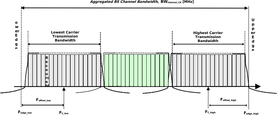
Figure 5.3A.2-1: Definition of Aggregated BS Channel Bandwidth for intra-band carrier aggregation
The aggregated BS Channel Bandwidth , BW Channel_CA , is defined as
BW Channel_CA = F edge,high - F edge,low (MHz)
The lower bandwidth edge F edge, low and the upper bandwidth edge F edge,high of the aggregated BS channel bandwidth are used as frequency reference points for transmitter and receiver requirements and are defined by
F edge,low = F C,low - F offset,low
F edge,high = F C,high + F offset,high
The lower and upper frequency offsets depend on the transmission bandwidth configurations of the lowest and highest assigned edge component carrier and are defined as
F offset,low = (N RB,low *12 + 1)*SCS low /2 + BW GB,low (MHz)
F offset,high = (N RB,high *12 - 1)*SCS high /2 + BW GB,high (MHz)
N RB,low and N RB,high are the transmission bandwidth configurations according to Table 5.3.2-1 or Table 5.3.2-2 or Table 5.3.2-3 for the lowest and highest assigned component carrier, SCS low and SCS high are the sub-carrier spacing for the lowest and highest assigned component carrier respectively. SCS low , SCS high , N RB,low , N RB,high , BW GB,low and BW GB,high use the largest μ value among the subcarrier spacing configurations supported in the operating band for both of the channel bandwidths according to Table 5.3.5-1 and BW GB,low and BW GB,high are the minimum guard band for lowest and highest assigned component carrier according to Table 5.3.3-1 for the said μ value. In case there is no common μ value for both of the channel bandwidths, μ =1 is used for SCS low , SCS high , N RB,low , N RB,high , BW GB,low and BW GB,high .
For intra-band non-contiguous carrier aggregation sub-block bandwidth and sub-block edges are defined as follows, see figure 5.3A.2-2.
FC,block 1,low
…
Lower Sub-block Edge
Upper Sub-block Edge
Transmission Bandwidth Configuration of the lowest carrier in a sub-block [RB]
F C,block 1,high
F offset_low
Transmission Bandwidth Configuration of the highest carrier in a sub-block [RB]
Resource block
Sub-block Bandwidth, BW Channel,block [MHz]
F edge,block 1, low
F edge,block 1,high
F offset_high
Sub block n
Sub block 1
Base Station RF Bandwidth
F C,block n,low
F C,block n,high
Sub-block Bandwidth, BW Channel,block [MHz]
F edge,block n, low
F edge,block n,high
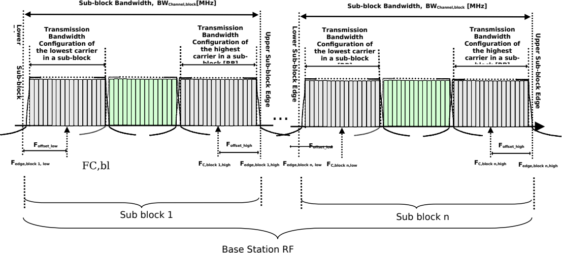
Figure 5.3A.2-2: Definition of sub-block bandwidth for intra-band non-contiguous spectrum
The lower sub-block edge of the sub-block bandwidth (BW Channel,block ) is defined as follows:
F edge,block, low = F C,block,low - F offset,low
The upper sub-block edge of the sub-block bandwidth is defined as follows:
F edge,block,high = F C,block,high + F offset,high
The sub-block bandwidth , BW Channel,block , is defined as follows:
BW Channel,block = F edge,block,high - F edge,block,low (MHz)
The lower and upper frequency offsets F offset,block,low and F offset,block,high depend on the transmission bandwidth configurations of the lowest and highest assigned edge component carriers within a sub-block and are defined as
F offset,block,low = (N RB,low *12 + 1)*SCS low /2 + BW GB,low (MHz)
F offset,block,high = (N RB,high *12 - 1)*SCS high /2 + BW GB,high (MHz)
where N RB,low and N RB,high are the transmission bandwidth configurations according to Table 5.3.2-1 or Table 5.3.2-2 for the lowest and highest assigned component carrier within a sub-block , respectively. SCS low and SCS high are the sub-carrier spacing for the lowest and highest assigned component carrier within a sub-block , respectively. SCS low , SCS high , N RB,low , N RB,high , BW GB,low and BW GB,high use the largest μ value among the subcarrier spacing configurations supported in the operating band for both of the channel bandwidths according to Table 5.3.5-1 and BW GB,low and BW GB,high are the minimum guard band for lowest and highest assigned component carrier according to Table 5.3.3-1 for the said μ value. In case there is no common μ value for both of the channel bandwidths, μ =1 is used for SCS low , SCS high , N RB,low , N RB,high , BW GB,low and BW GB,high .
The sub-block gap size between two consecutive sub-blocks W gap is defined as follows:
W gap = F edge,block n+1,low - F edge,block n,high (MHz)
5.4 Channel arrangement
5.4.1 Channel spacing
5.4.1.1 Channel spacing for adjacent NR carriers
The spacing between carriers will depend on the deployment scenario, the size of the frequency block available and the BS channel bandwidths . The nominal channel spacing between two adjacent NR carriers is defined as following:
- For NR FR1 operating bands with 100 kHz channel raster,
▪ Nominal Channel spacing = (BW Channel(1) + BW Channel(2) )/2
- For NR FR1 operating bands with 15 kHz channel raster,
▪ Nominal Channel spacing = (BW Channel(1) + BW Channel(2) )/2 + {-5 kHz, 0 kHz, 5 kHz} for ∆F Raster equals to 15 kHz
▪ Nominal Channel spacing = (BW Channel(1) + BW Channel(2) )/2 + {-10 kHz, 0 kHz, 10 kHz} for ∆F Raster equals to 30 kHz
- For NR FR2 operating bands with 60 kHz channel raster,
▪ Nominal Channel spacing = (BW Channel(1) + BW Channel(2) )/2 + {-20 kHz, 0 kHz, 20 kHz} for ∆F Raster equals to 60 kHz
▪ Nominal Channel spacing = (BW Channel(1) + BW Channel(2) )/2 + {-40 kHz, 0 kHz, 40 kHz} for ∆F Raster equals to 120 kHz
- For operating band n263
▪ Nominal Channel spacing = ceil((BW Channel(1) + BW Channel(2) )/100.8)*50.4 MHz,
where BW Channel(1) and BW Channel(2) are the BS channel bandwidths of the two respective NR carriers. The channel spacing can be adjusted depending on the channel raster to optimize performance in a particular deployment scenario.
For NR bands restricted to operation with shared-spectrum channel access, the maximum deviation from the nominal channel spacing is 40 kHz.
5.4.1.2 Channel spacing for CA
For intra-band contiguously aggregated carriers, the channel spacing between adjacent component carriers shall be multiple of least common multiple of channel raster and sub-carrier spacing.
The nominal channel spacing between two adjacent aggregated NR carriers is defined as follows:
For NR operating bands with 100 kHz channel raster:
For NR operating bands with 15 kHz channel raster:
with
For NR operating bands with 60kHz channel raster:
with
For operating band n263
Nominal Channel spacing = ceil((BW Channel(1) + BW Channel(2) )/100.8)*50.4 MHz,
where BWChannel(1) and BWChannel(2) are the BS channel bandwidths of the two respective NR component carriers according to Table 5.3.2-1, 5.3.2-2 and 5.3.2-3 with values in MHz,
The channel spacing for intra-band contiguous carrier aggregation can be adjusted to any multiple of least common multiple of channel raster and sub-carrier spacing less than the nominal channel spacing to optimize performance in a particular deployment scenario.
For intra-band contiguous carrier aggregation in NR bands restricted to operation with shared-spectrum channel access, the maximum deviation from the nominal channel spacing is 300 kHz.
For intra-band non-contiguous carrier aggregation , the channel spacing between two NR component carriers in different sub-blocks shall be larger than the nominal channel spacing defined in this clause.
5.4.2 Channel raster
5.4.2.1 NR-ARFCN and channel raster
The global frequency raster defines a set of RF reference frequencies F REF . The RF reference frequency is used in signalling to identify the position of RF channels, SS blocks and other elements. The global frequency raster is defined for all frequencies from 0 to 100 GHz. The granularity of the global frequency raster is ΔF Global .
RF reference frequencies are designated by an NR Absolute Radio Frequency Channel Number (NR-ARFCN) in the range [0…3279165] on the global frequency raster. The relation between the NR-ARFCN and the RF reference frequency F REF in MHz is given by the following equation, where F REF-Offs and N Ref-Offs are given in table 5.4.2.1-1 and N REF is the NR-ARFCN.
F REF = F REF-Offs + ΔF Global (N REF – N REF-Offs )
Table 5.4.2.1-1: NR-ARFCN parameters for the global frequency raster
| Range of frequencies (MHz) | ΔF Global (kHz) | F REF-Offs (MHz) | N REF-Offs | Range of N REF |
|---|---|---|---|---|
| 0 – 3000 | 5 | 0 | 0 | 0 – 599999 |
| 3000 – 24250 | 15 | 3000 | 600000 | 600000 – 2016666 |
| 24250 – 100000 | 60 | 24250.08 | 2016667 | 2016667 – 3279165 |
The channel raster defines a subset of RF reference frequencies that can be used to identify the RF channel position in the uplink and downlink. The RF reference frequency for an RF channel maps to a resource element on the carrier. For each operating band , a subset of frequencies from the global frequency raster are applicable for that band and forms a channel raster with a granularity ΔF Raster , which may be equal to or larger than ΔF Global .
For SUL bands except n95, n97, n98 and for the uplink of all FDD bands defined in table 5.2-1, for TDD bands n34, n38, n39, n48, n90, and n40,
F REF,shift = F REF + Δ shift , where Δ shift = 0 kHz or 7.5 kHz
where Δ shift is signalled by the network in higher layer parameter frequencyShift7p5khz as defined in TS 38.331 [11].
For bands n34, n38, n39, n48 and n40, F REF, shift is only applicable to uplink transmissions using a 15 kHz SCS.
The mapping between the channel raster and corresponding resource element is given in clause 5.4.2.2. The applicable entries for each operating band are defined in clause 5.4.2.3.
5.4.2.1A NB-IoT carrier frequency numbering
The NB-IoT carrier frequency numbering (EARFCN) is defined in clause 5.7 of TS 36.104 [4].
5.4.2.2 Channel raster to resource element mapping
The mapping between the RF reference frequency on the channel raster and the corresponding resource element is given in table 5.4.2.2-1 and can be used to identify the RF channel position. The mapping depends on the total number of RBs that are allocated in the channel and applies to both UL and DL. The mapping must apply to at least one numerology supported by the BS.
Table 5.4.2.2-1: Channel Raster to Resource Element Mapping
| Resource element index |
0 | 6 |
| Physical resource block index |

NRB is the transmission bandwidth configuration specified in sub-clause 5.3.2, is the PRB index within the NRB, and
5.4.2.3 Channel raster entries for each operating band
The RF channel positions on the channel raster in each NR operating band are given through the applicable NR-ARFCN in table 5.4.2.3-1 for FR1 and table 5.4.2.3-2 for FR2, using the channel raster to resource element mapping in clause 5.4.2.2.
-
For NR operating bands with 100 kHz channel raster, ΔF Raster = 20 × ΔF Global . In this case, every 20 th NR-ARFCN within the operating band are applicable for the channel raster within the operating band and the step size for the channel raster in table 5.4.2.3-1 is given as <20>.
-
For NR operating bands with 15 kHz channel raster below 3 GHz, ΔF Raster = I × ΔF Global , where I ϵ {3,6}. In this case, every I th NR-ARFCN within the operating band are applicable for the channel raster within the operating band and the step size for the channel raster in table 5.4.2.3-1 is given as < I >.
-
For NR operating bands with 15 kHz and 60 kHz channel raster above 3 GHz, ΔF Raster = I ×ΔF Global , where I ϵ {1, 2}. In this case, every I th NR-ARFCN within the operating band are applicable for the channel raster within the operating band and the step size for the channel raster in table 5.4.2.3-1 and table 5.4.2.3-2 is given as < I >.
-
For frequency bands with two ΔF Raster in FR1, the higher ΔF Raster applies to channels using only the SCS that is equal to or larger than the higher ΔF Raster and SSB SCS is equal to the higher ΔF Raster .
-
For frequency bands with two ΔF Raster in FR2, the higher ΔF Raster applies to channels using only the SCS that is equal to the higher ΔF Raster and the SSB SCS that is equal to or larger than the higher ΔF Raster .
Table 5.4.2.3-1: Applicable NR-ARFCN per operating band in FR1
| NR operating band | ΔF Raster (kHz) | Uplink range of N REF (First – <Step size> – Last) | Downlink range of N REF (First – <Step size> – Last) |
|---|---|---|---|
| n1 | 100 | 384000 – <20> – 396000 | 422000 – <20> – 434000 |
| n2 | 100 | 370000 – <20> – 382000 | 386000 – <20> – 398000 |
| n3 | 100 | 342000 – <20> – 357000 | 361000 – <20> – 376000 |
| n5 | 100 | 164800 – <20> – 169800 | 173800 – <20> – 178800 |
| n7 | 100 | 500000 – <20> – 514000 | 524000 – <20> – 538000 |
| n8 | 100 | 176000 – <20> – 183000 | 185000 – <20> – 192000 |
| n12 | 100 | 139800 – <20> – 143200 | 145800 – <20> – 149200 |
| n13 | 100 | 155400 – <20> – 157400 | 149200 – <20> – 151200 |
| n14 | 100 | 157600 – <20> –159600 | 151600 – <20> – 153600 |
| n18 | 100 | 163000 – <20> – 166000 | 172000 – <20> – 175000 |
| n20 | 100 | 166400 – <20> – 172400 | 158200 – <20> – 164200 |
| n25 | 100 | 370000 – <20> – 383000 | 386000 – <20> – 399000 |
| n24 | 100 | 325300 – <20> – 332100 | 305000 – <20> – 311800 |
| n26 | 100 | 162800 – <20> – 169800 | 171800 – <20> – 178800 |
| n28 | 100 | 140600 – <20> – 149600 | 151600 – <20> – 160600 |
| n29 | 100 | N/A | 143400 – <20> – 145600 |
| n30 | 100 | 461000 – <20> – 463000 | 470000 – <20> – 472000 |
| n31 | 100 | 90500 – <20> – 91500 | 92500 – <20> – 93500 |
| n34 | 100 | 402000 – <20> – 405000 | 402000 – <20> – 405000 |
| n38 | 100 | 514000 – <20> – 524000 | 514000 – <20> – 524000 |
| n39 | 100 | 376000 – <20> – 384000 | 376000 – <20> – 384000 |
| n40 | 100 | 460000 – <20> – 480000 | 460000 – <20> – 480000 |
| n41 | 15 | 499200 – <3> – 537999 | 499200 – <3> – 537999 |
| 30 | 499200 – <6> – 537996 | 499200 – <6> – 537996 | |
| n46 1 | 15 | 743334 – <1> – 795000 | 743334 – <1> – 795000 |
| n48 | 15 | 636667 – <1> – 646666 | 636667 – <1> – 646666 |
| 30 | 636668 – <2> – 646666 | 636668 – <2> – 646666 | |
| n50 | 100 | 286400 – <20> – 303400 | 286400 – <20> – 303400 |
| n51 | 100 | 285400 – <20> – 286400 | 285400 – <20> – 286400 |
| n53 | 100 | 496700 – <20> – 499000 | 496700 – <20> – 499000 |
| n54 | 100 | 334000 - <20> - 335000 | 334000 - <20> - 335000 |
| n65 | 100 | 384000 – <20> – 402000 | 422000 – <20> – 440000 |
| n66 | 100 | 342000 – <20> – 356000 | 422000 – <20> – 440000 |
| n67 | 100 | N/A | 147600 – <20> – 151600 |
| n68 | 100 | 139600 – <20> – 145600 | 150600 – <20> – 156600 |
| n70 | 100 | 339000 – <20> – 342000 | 399000 – <20> – 404000 |
| n71 | 100 | 132600 – <20> – 139600 | 123400 – <20> – 130400 |
| n72 | 100 | 90200 – <20> – 91200 | 92200 – <20> – 93200 |
| n74 | 100 | 285400 – <20> – 294000 | 295000 – <20> – 303600 |
| n75 | 100 | N/A | 286400 – <20> – 303400 |
| n76 | 100 | N/A | 285400 – <20> – 286400 |
| n77 | 15 | 620000 – <1> – 680000 | 620000 – <1> – 680000 |
| 30 | 620000 – <2> – 680000 | 620000 – <2> – 680000 | |
| n78 | 15 | 620000 – <1> – 653333 | 620000 – <1> – 653333 |
| 30 | 620000 – <2> – 653332 | 620000 – <2> – 653332 | |
| n79 | 15 | 693334 – <1> – 733333 | 693334 – <1> – 733333 |
| 30 | 693334 – <2> – 733332 | 693334 – <2> – 733332 | |
| n80 | 100 | 342000 – <20> – 357000 | N/A |
| n81 | 100 | 176000 – <20> – 183000 | N/A |
| n82 | 100 | 166400 – <20> – 172400 | N/A |
| n83 | 100 | 140600 – <20> –149600 | N/A |
| n84 | 100 | 384000 – <20> – 396000 | N/A |
| n85 | 100 | 139600 – <20> – 143200 | 145600 – <20> – 149200 |
| n86 | 100 | 342000 – <20> – 356000 | N/A |
| n87 | 100 | 82000 – <20> – 83000 | 84000 – <20> – 85000 |
| n88 | 100 | 82400 – <20> – 83400 | 84400 – <20> – 85400 |
| n89 | 100 | 164800 – <20> – 169800 | N/A |
| 15 | 499200 – <3> – 537999 | 499200 – <3> – 537999 | |
| n90 | 30 | 499200 – <6> – 537996 | 499200 – <6> – 537996 |
| 100 | 499200 – <20> – 538000 | 499200 – <20> – 538000 | |
| n91 | 100 | 166400 – <20> – 172400 | 285400 – <20> – 286400 |
| n92 | 100 | 166400 – <20> – 172400 | 286400 – <20> – 303400 |
| n93 | 100 | 176000 – <20> – 183000 | 285400 – <20> – 286400 |
| n94 | 100 | 176000 – <20> – 183000 | 286400 – <20> – 303400 |
| n95 | 100 | 402000 – <20> – 405000 | N/A |
| n96 2 | 15 | 795000 – <1> – 875000 | 795000 – <1> – 875000 |
| n97 | 100 | 460000 – <20> – 480000 | N/A |
| n98 | 100 | 376000 – <20> – 384000 | N/A |
| n99 | 100 | 325300 – <20> – 332100 | N/A |
| n100 | 100 | 174880 – <20> – 176000 | 183880 – <20> – 185000 |
| n101 | 100 | 380000 – <20> – 382000 | 380000 – <20> – 382000 |
| n102 3 | 15 | 795000 – <1> – 828333 | 795000 – <1> – 828333 |
| n104 | 15 | 828334 – <1> – 875000 | 828334 – <1> – 875000 |
| 30 | 828334 – <2> – 875000 | 828334 – <2> – 875000 | |
| n105 | 100 | 132600 – <20> – 140600 | 122400 – <20> – 130400 |
| n106 5 | 100 | 179200 – <20> – 180200 | 187000 – <20> – 188000 |
| n109 | 100 | 140600 – <20> – 146600 | 286400 – <20> – 303400 |
| n110 | 100 | 278000 – <20> – 279000 | 286400 – <20> – 287000 |
| n115 | 100 | 285580 – <20> – 292580 | 295180 – <20> – 302180 |
| NOTE 1: Applicable NR-ARFCN for band n46 for 10 MHz channel bandwidth, N REF = {782000, 788668} for 20 MHz channel bandwidth, N REF = {744000, 745332, 746668, 748000, 749332, 750668, 752000, 753332, 754668, 756000, 765332, 766668, 768000, 769332, 770668, 772000, 773332, 774668, 776000, 777332, 778668, 780000, 781332, 783000, 784332, 785668, 787000, 788332, 789668, 791000, 792332, 793668}; for 40 MHz channel bandwidth, N REF = {744668, 746000, 748668, 751332, 754000, 755332, 766000, 767332, 770000, 772668, 775332, 778000, 780668, 783668, 786332, 787668, 790332, 793000}; for 60 MHz channel bandwidth, N REF = {745332, 746668, 748000, 752000, 753332, 754668, 766668, 768000, 769332, 773332, 774668, 778668, 780000, 784332, 785668, 791000, 792332}; for 80 MHz channel bandwidth, N REF = {746000, 747332, 752668, 754000, 767332, 768668, 774000, 779332, 785000, 791668} for 100 MHz channel bandwidth, N REF = {746668, 753332, 768000, 791000} NOTE 2: Applicable NR-ARFCN for band n96 for 20 MHz channel bandwidth, N REF = {795668, 797000, 798332, 799668, 801000, 802332, 803668, 805000, 806332, 807668, 809000, 810332, 811668, 813000, 814332, 815668, 817000, 818332, 819668, 821000, 822332, 823668, 825000, 826332, 827668, 829000, 830332, 831668, 833000, 834332, 835668, 837000, 838332, 839668, 841000, 842332, 843668, 845000, 846332, 847668, 849000, 850332, 851668, 853000, 854332, 855668, 857000, 858332, 859668, 861000, 862332, 863668, 865000, 866332, 867668, 869000, 870332, 871668, 873000, 874332} for 40 MHz channel bandwidth, N REF = {797668, 800332, 803000, 805668, 808332, 811000, 813668, 816332, 819000, 821668, 824332, 827000, 829668, 832332, 835000, 837668, 840332, 843000, 845668, 848332, 851000, 853668, 856332, 859000, 861668, 864332, 867000, 869668, 872332} for 60 MHz channel bandwidth, N REF = {798332, 799668, 803668, 805000, 809000, 810332, 814332, 815668, 819668, 821000, 825000, 826332, 830332, 831668, 835668, 837000, 841000, 842332, 846332, 847668, 851668, 853000, 857000, 858332, 862332, 863668, 867668, 869000, 873000} for 80 MHz channel bandwidth, N REF = {799000, 804332, 809668, 815000, 820332, 825668, 831000, 836332, 841668, 847000, 852332, 857668, 863000, 868332} for 100 MHz channel bandwidth, N REF = {799668, 803668, 810332, 814332, 821000, 825000, 831668, 835668, 842332, 846332, 853000, 857000, 863668, 867668, 869000, 870332, 871668} NOTE 3: Applicable NR-ARFCN for band n102 for 20 MHz channel bandwidth, N REF = {795668, 797000, 798332, 799668, 801000, 802332, 803668, 805000, 806332, 807668, 809000, 810332, 811668, 813000, 814332, 815668, 817000, 818332, 819668, 821000, 822332, 823668, 825000, 826332, 827668} for 40 MHz channel bandwidth, N REF = {797668, 800332, 803000, 805668, 808332, 811000, 813668, 816332, 819000, 821668, 824332, 827000} for 60 MHz channel bandwidth, N REF = {798332, 799668, 803668, 805000, 809000, 810332, 814332, 815668, 819668, 821000, 825000, 826332} for 80 MHz channel bandwidth, N REF = {799000, 804332, 809668, 815000, 820332, 825668} for 100 MHz channel bandwidth, N REF = {799668, 803668, 810332, 814332, 821000, 825000} NOTE 4: Void NOTE 5: In the present version of the specification, only N REF 179800 and 187600 is applicable for 3 MHz channel bandwidth. |
Table 5.4.2.3-2: Applicable NR-ARFCN per operating band in FR2
| NR operating band | ΔF Raster (kHz) | Uplink and Downlink range of N REF (First – <Step size> – Last) |
|---|---|---|
| n257 | 60 | 2054166 – <1> – 2104165 |
| 120 | 2054167 – <2> – 2104165 | |
| n258 | 60 | 2016667 – <1> – 2070832 |
| 120 | 2016667 – <2> – 2070831 | |
| n259 | 60 | 2270833 – <1> – 2337499 |
| 120 | 2270833 – <2> – 2337499 | |
| n260 | 60 | 2229166 – <1> – 2279165 |
| 120 | 2229167 – <2> – 2279165 | |
| n261 | 60 | 2070833 – <1> – 2084999 |
| 120 | 2070833 – <2> – 2084999 | |
| n262 | 60 | 2399166 – <1> – 2415832 |
| n262 | 120 | 2399167 – <2> – 2415831 |
| n263 | 120 | See Table 5.4.2.3-3 |
| 480 | ||
| 960 |
Table 5.4.2.3-3: Applicable NR-ARFCN for operation in band n263
| Channel Bandwidth | Applicable NR-ARFCN |
|---|---|
| 100 MHz | 2564083 + 1680 * N, N = 0:137 |
| 400 MHz | 2566603 + 6720 * N, N = 0:33 |
| 800 MHz | 2569963 + 6720 * N, N = 0:32 |
| 1600 MHz | 2576683 + 6720 * N, N =0:30 |
| 2000 MHz | 2580043 + 6720 * N, N=0:29, 2585083, 2655643, 2692603, 2764843 |
For NR operating bands with 100 kHz channel raster, Enhanced channel raster is defined with ΔF Raster = 2 × ΔF Global . In this case every 2 th NR-ARFCN within the operating band are applicable for the channel raster within the operating band and the step size for the channel raster in Table 5.4.2.3-4 is given as <2>.
Table 5.4.2.3-4: Applicable NR-ARFCN per operating band for enhanced channel raster
| NR operating band | ΔF Raster (kHz) | Uplink Range of N REF (First – <Step size> – Last) | Downlink Range of N REF (First – <Step size> – Last) |
|---|---|---|---|
| n1 | 10 | 384000 – <2> – 396000 | 422000 – <2> – 434000 |
| n2 | 10 | 370000 – <2> – 382000 | 386000 – <2> – 398000 |
| n3 | 10 | 342000 – <2> – 357000 | 361000 – <2> – 376000 |
| n5 | 10 | 164800 – <2> – 169800 | 173800 – <2> – 178800 |
| n7 | 10 | 500000 – <2> – 514000 | 524000 – <2> – 538000 |
| n8 | 10 | 176000 – <2> – 183000 | 185000 – <2> – 192000 |
| n12 | 10 | 139800 – <2> – 143200 | 145800 – <2> – 149200 |
| n13 | 10 | 155400 – <2> – 157400 | 149200 – <2> – 151200 |
| n14 | 10 | 157600 – <2> – 159600 | 151600 – <2> – 153600 |
| n18 | 10 | 163000 – <2> – 166000 | 172000 – <2> – 175000 |
| n20 | 10 | 166400 – <2> – 172400 | 158200 – <2> – 164200 |
| n24 | 10 | 325300 – <2> – 332100 | 305000 – <2> – 311800 |
| n25 | 10 | 370000 – <2> – 383000 | 386000 – <2> – 399000 |
| n26 | 10 | 162800 – <2> – 169800 | 171800 – <2> – 178800 |
| n28 | 10 | 140600 – <2> – 149600 | 151600 – <2> – 160600 |
| n29 | 10 | N/A | 143400 – <2> – 145600 |
| n30 | 10 | 461000 – <2> – 463000 | 470000 – <2> – 472000 |
| n34 | 10 | 402000 – <2> – 405000 | 402000 – <2> – 405000 |
| n38 | 10 | 514000 – <2> – 524000 | 514000 – <2> – 524000 |
| n39 | 10 | 376000 – <2> – 384000 | 376000 – <2> – 384000 |
| n40 | 10 | 460000 – <2> – 480000 | 460000 – <2> – 480000 |
| n50 | 10 | 286400 – <2> – 303400 | 286400 – <2> – 303400 |
| n53 | 10 | 496700 – <2> – 499000 | 496700 – <2> – 499000 |
| n65 | 10 | 384000 – <2> – 402000 | 422000 – <2> – 440000 |
| n66 | 10 | 342000 – <2> – 356000 | 422000 – <2> – 440000 |
| n67 | 10 | N/A | 147600 – <2> – 151600 |
| n68 | 10 | 139600 – <2> – 145600 | 150600 – <2> – 156600 |
| n70 | 10 | 339000 – <2> – 342000 | 399000 – <2> – 404000 |
| n71 | 10 | 132600 – <2> – 139600 | 123400 – <2> – 130400 |
| n74 | 10 | 285400 – <2> – 294000 | 295000 – <2> – 303600 |
| n75 | 10 | N/A | 286400 – <2> – 303400 |
| n80 | 10 | 342000 – <2> – 357000 | N/A |
| n81 | 10 | 176000 – <2> – 183000 | N/A |
| n82 | 10 | 166400 – <2> – 172400 | N/A |
| n83 | 10 | 140600 – <2> –149600 | N/A |
| n84 | 10 | 384000 – <2> – 396000 | N/A |
| n85 | 10 | 139600 – <2> – 143200 | 145600 – <2> – 149200 |
| n86 | 10 | 342000 – <2> – 356000 | N/A |
| n89 | 10 | 164800 – <2> – 169800 | N/A |
| n90 | 10 | 499200 – <2> – 538000 | 499200 – <2> – 538000 |
| n91 | 10 | 166400 – <2> – 172400 | 285400 – <2> – 286400 |
| n92 | 10 | 166400 – <2> – 172400 | 286400 – <2> – 303400 |
| n93 | 10 | 176000 – <2> – 183000 | 285400 – <2> – 286400 |
| n94 | 10 | 176000 – <2> – 183000 | 286400 – <2> – 303400 |
| n95 | 10 | 402000 – <2> – 405000 | N/A |
| n97 | 10 | 460000 – <2> – 480000 | N/A |
| n98 | 10 | 376000 – <2> – 384000 | N/A |
| n99 | 10 | 325300 – <2> – 332100 | N/A |
| n100 | 10 | 174880 – <2> – 176000 | 183880 – <2> – 185000 |
| n101 | 10 | 380000 – <2> – 382000 | 380000 – <2> – 382000 |
| n105 | 10 | 132600 – <2> – 140600 | 122400 – <2> – 130400 |
| n109 | 10 | 140600 – <2> – 146600 | 286400 – <2> – 303400 |
| n115 | 10 | 285580 – <2> – 292580 | 295180 – <2> – 302180 |
| NOTE 1: The channel numbers that designate carrier frequencies so close to the operating band edges that the carrier extends beyond the operating band edge shall not be used. These channel numbers shall also be such that the minimum guard band for each channel bandwidth and SCS specified in Table 5.3.3-1 are met for carriers located at the upper or lower edge of an operating band. | NOTE 1: The channel numbers that designate carrier frequencies so close to the operating band edges that the carrier extends beyond the operating band edge shall not be used. These channel numbers shall also be such that the minimum guard band for each channel bandwidth and SCS specified in Table 5.3.3-1 are met for carriers located at the upper or lower edge of an operating band. | NOTE 1: The channel numbers that designate carrier frequencies so close to the operating band edges that the carrier extends beyond the operating band edge shall not be used. These channel numbers shall also be such that the minimum guard band for each channel bandwidth and SCS specified in Table 5.3.3-1 are met for carriers located at the upper or lower edge of an operating band. | NOTE 1: The channel numbers that designate carrier frequencies so close to the operating band edges that the carrier extends beyond the operating band edge shall not be used. These channel numbers shall also be such that the minimum guard band for each channel bandwidth and SCS specified in Table 5.3.3-1 are met for carriers located at the upper or lower edge of an operating band. |
5.4.3 Synchronization raster
5.4.3.1 Synchronization raster and numbering
The synchronization raster indicates the frequency positions of the synchronization block that can be used by the UE for system acquisition when explicit signalling of the synchronization block position is not present.
A global synchronization raster is defined for all frequencies. The frequency position of the SS block is defined as SS REF with corresponding number GSCN. The parameters defining the SS REF and GSCN for all the frequency ranges are in table 5.4.3.1-1 for above 3 MHz channel bandwidth and in table 5.4.3.1-2 for 3 MHz channel bandwidth.
For band n100, additional parameters defining the SS REF and GSCN are specified in table 5.4.3.1-3.
The resource element corresponding to the SS block reference frequency SS REF is given in clause 5.4.3.2. The synchronization raster and the subcarrier spacing of the synchronization block is defined separately for each band.
The synchronization raster and the corresponding SS block do not cover all possible RF channel bandwidths and locations on Enhanced channel raster.
Table 5.4.3.1-1: GSCN parameters for the global frequency raster for above 3 MHz channel bandwidth
| Range of frequencies (MHz) | SS block frequency position SS REF | GSCN | Range of GSCN |
|---|---|---|---|
| 0 – 3000 | N * 1200 kHz + M * 50 kHz, N = 1:2499, M ϵ {1,3,5} | 3N + (M-3)/2 | 2 2 – 7498 |
| 3000 – 24250 | 3000 MHz + N * 1.44 MHz, N = 0:14756 | 7499 + N | 7499 – 22255 |
| 24250 – 100000 | 24250.08 MHz + N * 17.28 MHz, N = 0:4383 | 22256 + N | 22256 – 26639 |
| NOTE 1: The default value for operating bands which only support SCS spaced channel raster(s) is M=3. NOTE 2: GSCN=2 (corresponding to ARFCN-ValueNR = 250) is a reserved value paired with reserved operating band n200. |
Table 5.4.3.1-2: GSCN parameters for the global frequency raster for 3 MHz channel bandwidth
| Range of frequencies (MHz) | SS block frequency position SS REF | GSCN | Range of GSCN |
|---|---|---|---|
| 0 – 1000, 1432-1435 | N * 600 kHz + M * 50 kHz + 300 kHz, N = 1:1665, M ϵ {1,3,5}, N = 2388, M ϵ {3,5} or N = 2389, M ϵ {1} (Note 1) | 26638 + 3N + (M-3)/2 | 26640 – 31634, 33802 - 33804 |
| NOTE 1: Only applicable for 15 PRB transmission bandwidth configuration within 3 MHz channel bandwidth with punctured PBCH defined in TS 38.211 [9] clause 7.4.3.1. | NOTE 1: Only applicable for 15 PRB transmission bandwidth configuration within 3 MHz channel bandwidth with punctured PBCH defined in TS 38.211 [9] clause 7.4.3.1. | NOTE 1: Only applicable for 15 PRB transmission bandwidth configuration within 3 MHz channel bandwidth with punctured PBCH defined in TS 38.211 [9] clause 7.4.3.1. | NOTE 1: Only applicable for 15 PRB transmission bandwidth configuration within 3 MHz channel bandwidth with punctured PBCH defined in TS 38.211 [9] clause 7.4.3.1. |
Table 5.4.3.1-3: Additional GSCN parameters for the global frequency raster and for band n100
| SS block frequency position SS REF (MHz) | GSCN | Note |
|---|---|---|
| 920.73 | 41637 | Only applicable for 12 PRB transmission bandwidth configuration within 3 MHz channel with punctured PBCH defined in TS 38.211 [9] clause 7.4.3.1. |
| 921.45 | 41638 | Only applicable for 20 PRB transmission bandwidth configuration within 5 MHz channel with unpunctured PBCH defined in TS 38.211 [9] clause 7.4.3.1. |
5.4.3.2 Synchronization raster to synchronization block resource element mapping
The mapping between the synchronization raster and the corresponding resource element of the SS block is given in table 5.4.3.2-1.
Table 5.4.3.2-1: Synchronization Raster to SS block Resource Element Mapping
| Resource element index k | 120 |
|---|---|
k is the subcarrier number of SS/PBCH block defined in TS 38.211 clause 7.4.3.1 [9].
5.4.3.3 Synchronization raster entries for each operating band
For FR1 and for above 3 MHz channel bandwidth, the synchronization raster for each band is given in table 5.4.3.3-1. The distance between applicable GSCN entries is given by the <Step size> indicated in table 5.4.3.3-1.
For FR1 and for 3 MHz channel bandwidth, the synchronization raster for each band is given in table 5.4.3.3-4. The distance between applicable GSCN entries is given by the <Step size> indicated in table 5.4.3.3-4.
For FR2, the synchronization raster for each band is given in table 5.4.3.3-2. The distance between applicable GSCN entries is given by the <Step size> indicated in table 5.4.3.3-2.
Table 5.4.3.3-1: Applicable SS raster entries per operating band (FR1) for above 3 MHz channel bandwidth
| NR operating band | SS Block SCS | SS Block pattern (NOTE 1) | Range of GSCN (First – <Step size> – Last) |
|---|---|---|---|
| n1 | 15 kHz | Case A | 5279 – <1> – 5419 |
| n2 | 15 kHz | Case A | 4829 – <1> – 4969 |
| n3 | 15 kHz | Case A | 4517 – <1> – 4693 |
| n5 | 15 kHz | Case A | 2177 – <1> – 2230 |
| 30 kHz | Case B | 2183 – <1> – 2224 | |
| n7 | 15 kHz | Case A | 6554 – <1> – 6718 |
| n8 | 15 kHz | Case A | 2318 – <1> – 2395 |
| n12 | 15 kHz | Case A | 1828 – <1> – 1858 |
| n13 | 15 kHz | Case A | 1871 – <1> – 1885 |
| n14 | 15 kHz | Case A | 1901 – <1> – 1915 |
| n18 | 15 kHz | Case A | 2156 – <1> – 2182 |
| n20 | 15 kHz | Case A | 1982 – <1> – 2047 |
| n24 | 15 kHz | Case A | 3818 – <1> – 3892 |
| n24 | 30 kHz | Case B | 3824 – <1> – 3886 |
| n25 | 15 kHz | Case A | 4829 – <1> – 4981 |
| n26 | 15 kHz | Case A | 2153 – <1> – 2230 |
| n28 | 15 kHz | Case A | 1901 – <1> – 2002 |
| n29 | 15 kHz | Case A | 1798 – <1> – 1813 |
| n30 | 15 kHz | Case A | 5879 – <1> – 5893 |
| n31 | 15 kHz | Case A | 1161 – <1> – 1162 |
| n34 | 15 kHz | Case A | NOTE 3 |
| 30 kHz | Case C | 5036 – <1> – 5050 | |
| n38 | 15 kHz | Case A | NOTE 2 |
| 30 kHz | Case C | 6437 – <1> – 6538 | |
| n39 | 15 kHz | Case A | NOTE 4 |
| 30 kHz | Case C | 4712 – <1> – 4789 | |
| n40 | 30 kHz | Case C | 5762 – <1> – 5989 |
| n41 | 15 kHz | Case A | 6246 – <3> – 6717 |
| 30 kHz | Case C | 6252 – <3> – 6714 | |
| n46 5 | 30 kHz | Case C | 8993 – <1> – 9530 |
| n48 | 30 kHz | Case C | 7884 – <1> – 7982 |
| n50 | 30 kHz | Case C | 3590 – <1> – 3781 |
| n51 | 15 kHz | Case A | 3572 – <1> – 3574 |
| n53 | 15 kHz | Case A | 6215 – <1> – 6232 |
| 30 kHz | Case C | 6221 – <1> – 6226 | |
| n54 | 15 kHz | Case A | 4181 - <1> - 4182 |
| n65 | 15 kHz | Case A | 5279 – <1> – 5494 |
| n66 | 15 kHz | Case A | 5279 – <1> – 5494 |
| 30 kHz | Case B | 5285 – <1> – 5488 | |
| n67 | 15 kHz | Case A | 1850 – <1> – 1888 |
| n68 | 15 kHz | Case A | 1888 – <1> – 1951 |
| n70 | 15 kHz | Case A | 4993 – <1> – 5044 |
| n71 | 15 kHz | Case A | 1547 – <1> – 1624 |
| n72 | 15 kHz | Case A | 1157 – <1> – 1159 |
| n74 | 15 kHz | Case A | 3692 – <1> – 3790 |
| n75 | 15 kHz | Case A | 3584 – <1> – 3787 |
| n76 | 15 kHz | Case A | 3572 – <1> – 3574 |
| n77 | 30 kHz | Case C | 7711 – <1> – 8329 |
| n78 | 30 kHz | Case C | 7711 – <1> – 8051 |
| n79 | 30 kHz | Case C | 8480 – <16> – 8880 7 |
| 8475 – <1> – 8884 8 | |||
| n85 | 15 kHz | Case A | 1826 – <1> – 1858 |
| n87 | 15 kHz | Case A | 1055 – <1> – 1057 |
| n88 | 15 kHz | Case A | 1061 – <1> – 1062 |
| n90 | 15 kHz | Case A | 6246 – <1> – 6717 10 |
| 15 kHz | Case A | 6245 – <1> – 6718 11 | |
| 30 kHz | Case C | 6252 – <1> – 6714 | |
| n91 | 15 kHz | Case A | 3572 – <1> – 3574 |
| n92 | 15 kHz | Case A | 3584 – <1> – 3787 |
| n93 | 15 kHz | Case A | 3572 – <1> – 3574 |
| n94 | 15 kHz | Case A | 3584 – <1> – 3787 |
| n96 6 | 30 kHz | Case C | 9531 – <1> – 10363 |
| n100 | 15 kHz | Case A | 2303 – <1> – 2307, 41638 12 |
| n101 | 15 kHz | Case A | 4754 – <1> – 4768 |
| n101 | 30 kHz | Case C | 4760 – <1> – 4764 |
| n102 9 | 30 kHz | Case C | 9531 – <1> – 9877 |
| n104 | 30 kHz | Case C | 9882 – <7> – 10358 |
| n105 | 15 kHz | Case A | 1535 – <1> – 1624 |
| n109 | 15 kHz | Case A | 3584 – <1> – 3787 |
| n115 | 15 kHz | Case A | 3695 – <1> – 3772 |
| NOTE 1: SS Block pattern is defined in clause 4.1 in TS 38.213 [10]. NOTE 2: The applicable SS raster entries are GSCN = {6432, 6443, 6457, 6468, 6479, 6493, 6507, 6518, 6532, 6543} NOTE 3: The applicable SS raster entries are GSCN = {5032, 5043, 5054} NOTE 4: The applicable SS raster entries are GSCN = {4707, 4715, 4718, 4729, 4732, 4743, 4747, 4754, 4761, 4768, 4772, 4782, 4786, 4793} NOTE 5: The following GSCN are allowed for operation in band n46: GSCN = {8996, 9010, 9024, 9038, 9051, 9065, 9079, 9093, 9107, 9121, 9218, 9232, 9246, 9260, 9274, 9288, 9301, 9315, 9329, 9343, 9357, 9371, 9385, 9402, 9416, 9430, 9444, 9458, 9472, 9485, 9499, 9513}. NOTE 6: The following GSCN are allowed for operation in band n96: GSCN = { 9548, 9562, 9576, 9590, 9603, 9617, 9631, 9645, 9659, 9673, 9687, 9701, 9714, 9728, 9742, 9756, 9770, 9784, 9798, 9812, 9826, 9840, 9853, 9867, 9881, 9895, 9909, 9923, 9937, 9951, 9964, 9978, 9992, 10006, 10020, 10034, 10048, 10062, 10076, 10090, 10103, 10117, 10131, 10145, 10159, 10173, 10187, 10201, 10214, 10228, 10242, 10256, 10270, 10284, 10298, 10312, 10325, 10339, 10353}. NOTE 7: The SS raster entries apply for channel bandwidths larger than or equal to 40 MHz. NOTE 8: The SS raster entries apply for channel bandwidths smaller than 40 MHz. NOTE 9: The following GSCN are allowed for operation in band n102: GSCN = {9535, 9548, 9562, 9576, 9590, 9603, 9617, 9631, 9645, 9659, 9673, 9687, 9701, 9714, 9728, 9742, 9756, 9770, 9784, 9798, 9812, 9826, 9840, 9853, 9867} NOTE 10: The SS raster entries apply for channel bandwidths larger than or equal to 10 MHz. NOTE 11: The SS raster entries apply for channel bandwidth equal to 5 MHz. NOTE 12: Only applicable for 20 PRB transmission bandwidth configuration within 5 MHz channel with unpunctured PBCH defined in TS 38.211 [9] clause 7.4.3.1. |
Table 5.4.3.3-2: Applicable SS raster entries per operating band (FR2)
| NR operating band | SS Block SCS | SS Block pattern (note 1) | Range of GSCN (First – <Step size> – Last) |
|---|---|---|---|
| n257 | 120 kHz | Case D | 22388 – <1> – 22558 |
| 240 kHz | Case E | 22390 – <2> – 22556 | |
| n258 | 120 kHz | Case D | 22257 – <1> – 22443 |
| 240 kHz | Case E | 22258 – <2> – 22442 | |
| n259 | 120 kHz | Case D | 23140 – <1> – 23369 |
| 240 kHz | Case E | 23142 – <2> – 23368 | |
| n260 | 120 kHz | Case D | 22995 – <1> – 23166 |
| 240 kHz | Case E | 22996 – <2> – 23164 | |
| n261 | 120 kHz | Case D | 22446 – <1> – 22492 |
| 240 kHz | Case E | 22446 – <2> – 22490 | |
| n262 | 120 kHz | Case D | 23586 – <1> – 23641 |
| 240 kHz | Case E | 23588 – <2> – 23640 | |
| n263 | 120 kHz | Case D | Table 5.4.3.3-3 |
| 480 kHz | Case F | ||
| 960 kHz 2 | Case G | 24162 – <6> – 24954 | |
| NOTE 1: SS Block pattern is defined in section 4.1 in TS 38.213 [10]. NOTE 2: SS Block SCS of 960 kHz is not used for initial access. |
Table 5.4.3.3-3: Allowed GSCN for operation in band n263 for 120 kHz and 480 kHz
| SS Block SCS | Range of GSCN |
|---|---|
| 120 kHz | 24156 + 6 * N – 3 * floor((N+5)/18), N=0:137 |
| 480 kHz | 24162 + 24 * N – 12 * floor((N+4)/18), N=0:33 |
Table 5.4.3.3-4: Applicable SS raster entries per operating band (FR1) for 3 MHz channel bandwidth
| NR operating band | SS Block SCS | SS Block pattern (NOTE 1) | Range of GSCN (First – <Step size> – Last) |
|---|---|---|---|
| n5 | 15 kHz | Case A | 30987 – <1> – 31100 |
| n12 | 15 kHz | Case A | 30288 – <1> – 30359 |
| n26 | 15 kHz | Case A | 30937 – <1> – 31100 |
| n28 | 15 kHz | Case A | 30432 – <1> – 30644 |
| n31 | 15 kHz | Case A | 28955 – <1> – 28967 |
| n72 | 15 kHz | Case A | 28947 – <1> – 28959 |
| n85 | 15 kHz | Case A | 30282 – <1> – 30359 |
| n87 | 15 kHz | Case A | 28743 – <1> – 28754 |
| n88 | 15 kHz | Case A | 28752 – <1> – 28764 |
| n100 | 15 kHz | Case A | 31240 – <1> – 31242, 31244 – <1> – 31253, 41637 2 |
| n106 | 15 kHz | Case A | 31317 – <1> – 31329 |
| n110 | 15 kHz | Case A | 33802 – <1> – 33804 |
| NOTE 1: SS Block pattern is defined in clause 4.1 in TS 38.213 [10]. NOTE 2: Only applicable for 12 PRB transmission bandwidth configuration within 3 MHz channel with punctured PBCH defined in TS 38.211 [9] clause 7.4.3.1. |
6 Conducted transmitter characteristics
6.1 General
Unless otherwise stated, the conducted transmitter characteristics are specified at the antenna connector for BS type 1-C and at the TAB connector for BS type 1-H , with a full complement of transceiver units for the configuration in normal operating conditions.
For BS type 1-H the manufacturer shall declare the minimum number of supported geographical cells (i.e. geographical areas covered by beams). The minimum number of supported geographical cells (N cells ) relates to the BS setting with the minimum amount of cell splitting supported with transmission on all TAB connectors supporting the operating band , or with minimum amount of transmitted beams.
For BS type 1-H manufacturer shall also declare TAB connector TX min cell groups . Every TAB connector of the BS type 1-H supporting transmission in an operating band shall map to one TAB connector TX min cell group supporting the same operating band , where mapping of TAB connector s to cells/beams is implementation dependent.
The number of active transmitter units that are considered when calculating the conducted TX emissions limits (N TXU,counted ) for BS type 1-H is calculated as follows:
N TXU,counted = min(N TXU,active , 8×N cells )
N TXU,countedpercell is used for scaling of basic limits and is derived as N TXU,countedpercell = N TXU,counted / N cells
NOTE: N TXU,active depends on the actual number of active transmitter unit s and is independent to the declaration of N cells .
For BS type 1-H there is no requirement specified for band n46, n100 and n101 and n102.
The requirements for NB-IoT are not applied for ATG BS.
Unless stated otherwise, the requirements for BS type 1-C and BS type 1-H are applied for ATG BS type 1-C and 1-H , respectively.
6.2 Base station output power
6.2.1 General
The BS conducted output power requirement is at antenna connector for BS type 1-C , or at TAB connector for BS type 1-H .
The rated carrier output power of the BS type 1-C shall be as specified in table 6.2.1-1.
Table 6.2.1-1: BS type 1-C rated output power limits for BS classes
| BS class | P rated,c,AC |
|---|---|
| Wide Area BS | (Note) |
| Medium Range BS | ≤ 38 dBm |
| Local Area BS | ≤ 24 dBm |
| NOTE: There is no upper limit for the P rated,c,AC rated output power of the Wide Area Base Station. |
For operation in bands n100 and n101 in CEPT countries subject to the ECC Decision (20)02 [21], the WA BS requirement in table 6.2.1-1 apply in case of coordinated RMR BS deployments, while the requirements in clause 6.2.4 apply in case of uncoordinated RMR BS deployments.
The rated carrier output power of the BS type 1-H shall be as specified in table 6.2.1-2.
Table 6.2.1-2: BS type 1-H rated output power limits for BS classes
| BS class | P rated,c,sys | P rated,c,TABC |
|---|---|---|
| Wide Area BS | (Note) | (Note) |
| Medium Range BS | ≤ 38 dBm +10log(N TXU,counted ) | ≤ 38 dBm |
| Local Area BS | ≤ 24 dBm +10log(N TXU,counted ) | ≤ 24 dBm |
| NOTE: There is no upper limit for the P rated,c,sys or P rated,c,TABC of the Wide Area Base Station. |
In addition, for operation with shared spectrum channel access operation, the BS may have to comply with the applicable BS power limits established regionally, when deployed in regions where those limits apply and under the conditions declared by the manufacturer.
6.2.2 Minimum requirement for BS type 1-C
In normal conditions, P max,c,AC shall remain within +2 dB and -2 dB of the rated carrier output power P rated,c,AC , declared by the manufacturer.
In extreme conditions, P max,c,AC shall remain within +2.5 dB and -2.5 dB of the rated carrier output power P rated,c,AC , declared by the manufacturer.
In certain regions, the minimum requirement for normal conditions may apply also for some conditions outside the range of conditions defined as normal.
NOTE: For NB-IoT operation in NR in-band, the NR carrier and NB-IoT carrier shall be seen as a single carrier occupied NR channel bandwidth, the output power over this carrier is shared between NR and NB-IoT. This note shall apply for P max,c,AC and P rated,c,AC .
6.2.3 Minimum requirement for BS type 1-H
In normal conditions, P max,c,TABC shall remain within +2 dB and -2 dB of the rated carrier output power P rated,c,TABC for each TAB connector as declared by the manufacturer.
In extreme conditions, P max,c,TABC shall remain within +2.5 dB and -2.5 dB of the rated carrier output power P rated,c,TABC for each TAB connector as declared by the manufacturer.
In certain regions, the minimum requirement for normal conditions may apply also for some conditions outside the range of conditions defined as normal.
6.2.4 Additional requirements (regional)
In certain regions, additional regional requirements may apply.
For Band n41 and n90 operation in Japan, the rated output power, P rated,c.sys for BS type 1-H or sum of P rated,c,AC over all antenna connectors for BS type 1-C declared by the manufacturer shall be equal to or less than 20 W per 10 MHz bandwidth.
For band n100 in CEPT countries subject to the ECC Decision (20)02 [21], P rated,c,AC of the WA BS shall be as specified in table 6.2.4-1.
Table 6.2.4-1: WA BS P rated,c,AC in band n100
| Channel bandwidth | P rated,c,AC (NOTE 1) |
|---|---|
| 3MHz (NOTE 2) | ≤ 48 dBm/3MHz + (f DL -921.4) x 40/3 dB |
| 5MHz | ≤ 51.5 dBm/5MHz + (f D L-922.1) x 40/3 dB |
| NOTE 1: f DL = centre frequency in MHz NOTE 2 : f DL ≤ 922.5 MHz. No additional output power restriction for f DL > 922.5MHz |
This limit is derived from ECC Decision (20)02 [21] assuming a 17 dBi maximum antenna gain and 4 dB losses, and assuming one antenna connector. The above rated output power limit for band n100 applies to uncoordinated deployments and in case of coordinated deployments, higher output power values may be allowed.
For CEPT countries subject to the ECC Decision (20)02 [21], administrations wishing to allow multiple carriers, i.e., more than one wideband carrier (LTE, NR, NB-IoT standalone, or NR/LTE with NB-IoT in-band) in band n100, should consider the implementation of a coordination procedure or other mitigation measures.
NOTE 1: For more details on the maximum level derivation, refer to TR 38.853 [23].
NOTE 2: Void.
NOTE 3: Standalone NB-IoT operation is specified in TS 36.104 [13].
For band n101 in CEPT countries subject to the ECC Decision (20)02 [21], P rated,c,AC shall not exceed 51 dBm/10MHz or 48 dBm/5MHz. This limit is derived from ECC Decision (20)02 [21] assuming a 18 dBi maximum antenna gain and 4 dB losses, and assuming one antenna connector. The above rated output power limit for band n101 applies to uncoordinated deployments and in case of coordinated deployments, higher output power values may be allowed.
For CEPT countries subject to the ECC Decision (20)02 [21], administrations wishing to allow multiple carriers, i.e., more than one wideband carrier (LTE, NR, NB-IoT standalone, or NR/LTE with NB-IoT in-band) in band n101, should consider the implementation of a coordination procedure or other mitigation measures.
NOTE 4: For more details on the maximum level derivation, refer to TR 38.852 [22].
NOTE 5: Standalone NB-IoT operation is specified in TS 36.104 [13].
6.3 Output power dynamics
6.3.1 General
The requirements in clause 6.3 apply during the transmitter ON period . Transmitted signal quality (as specified in clause 6.5) shall be maintained for the output power dynamics requirements of this clause.
Power control is used to limit the interference level.
6.3.2 RE power control dynamic range
6.3.2.1 General
The RE power control dynamic range is the difference between the power of an RE and the average RE power for a BS at maximum output power (P max,c,AC or P max,c,TABC ) for a specified reference condition.
For BS type 1-C this requirement shall apply at the antenna connector supporting transmission in the operating band .
For BS type 1-H this requirement shall apply at each TAB connector supporting transmission in the operating band .
6.3.2.2 Minimum requirement for BS type 1-C and BS type 1-H
RE power control dynamic range:
Table 6.3.2.2-1: RE power control dynamic range
| Modulation scheme used | RE power control dynamic range (dB) | RE power control dynamic range (dB) |
|---|---|---|
| on the RE | (down) | (up) |
| QPSK (PDCCH) | -6 | +4 |
| QPSK (PDSCH) | -6 | +3 |
| 16QAM (PDSCH) | -3 | +3 |
| 64QAM (PDSCH) | 0 | 0 |
| 256QAM (PDSCH) | 0 | 0 |
| 1024QAM (PDSCH) | 0 | 0 |
| NOTE: The output power per carrier shall always be less or equal to the maximum output power of the base station. | NOTE: The output power per carrier shall always be less or equal to the maximum output power of the base station. | NOTE: The output power per carrier shall always be less or equal to the maximum output power of the base station. |
6.3.3 Total power dynamic range
6.3.3.1 General
The BS total power dynamic range is the difference between the maximum and the minimum transmit power of an OFDM symbol for a specified reference condition.
For BS type 1-C this requirement shall apply at the antenna connector supporting transmission in the operating band .
For BS type 1-H this requirement shall apply at each TAB connector supporting transmission in the operating band .
NOTE 1: The upper limit of the dynamic range is the OFDM symbol power for a BS when transmitting on all RBs at maximum output power. The lower limit of the total power dynamic range is the average power for single RB transmission. The OFDM symbol shall carry PDSCH and not contain RS or SSB.
NOTE 2: The requirement does not apply to operation with shared spectrum channel access.
6.3.3.2 Minimum requirement for BS type 1-C and BS type 1-H
The downlink (DL) total power dynamic range for each NR carrier shall be larger than or equal to the level in table 6.3.3.2-1.
Table 6.3.3.2-1: Total power dynamic range
| BS channel | Total power dynamic range (dB) | Total power dynamic range (dB) | Total power dynamic range (dB) |
|---|---|---|---|
| bandwidth (MHz) | 15 kHz SCS | 30 kHz SCS | 60 kHz SCS |
| 3 | 11.7 | N/A | N/A |
| 5 | 13.9 | 10.4 | N/A |
| 7 | 15.4 | N/A | N/A |
| 10 | 17.1 | 13.8 | 10.4 |
| 15 | 18.9 | 15.7 | 12.5 |
| 20 | 20.2 | 17 | 13.8 |
| 25 | 21.2 | 18.1 | 14.9 |
| 30 | 22 | 18.9 | 15.7 |
| 35 | 22.7 | 19.6 | 16.4 |
| 40 | 23.3 | 20.2 | 17 |
| 45 | 23.8 | 20.7 | 17.6 |
| 50 | 24.3 | 21.2 | 18.1 |
| 60 | N/A | 22 | 18.9 |
| 70 | N/A | 22.7 | 19.6 |
| 80 | N/A | 23.3 | 20.2 |
| 90 | N/A | 23.8 | 20.8 |
| 100 | N/A | 24.3 | 21.3 |
6.3.4 NB-IoT RB power dynamic range for NB-IoT operation in NR in-band
6.3.4.1 General
The NB-IoT RB power dynamic range (or NB-IoT power boosting) is the difference between the average power of NB-IoT REs (which occupy certain REs within a NR transmission bandwidth configuration plus 15 kHz at each edge but not within the NR minimum guard band GB Channel ) and the average power over all REs (from both NB-IoT and the NR carrier containing the NB-IoT REs).
6.3.4.2 Minimum Requirement
NB-IoT RB power dynamic range for NB-IoT operation in NR in-band shall be larger than or equal to the level specified in Table 6.3.4.2-1. This power dynamic range level is only required for one NB-IoT RB.
Table 6.3.4.2-1: NB-IoT RB power dynamic range for NB-IoT operation in NR in-band
| BS channel bandwidth (MHz) | NB-IoT RB frequency position | NB-IoT RB power dynamic range (dB) |
|---|---|---|
| 3, 5, 7, 10 | Any | +6 |
| 15 | Within center 77*180kHz+15kHz at each edge | +6 |
| Other | +3 | |
| 20 | Within center 102*180kHz+15kHz at each edge | +6 |
| Other | +3 | |
| 25, 30, 35, 40, 45, 50, 60, 70, 80, 90, 100 | Within center 90% of BS channel bandwidth | +6 |
| Other | +3 |
6.4 Transmit ON/OFF power
6.4.1 Transmitter OFF power
6.4.1.1 General
Transmit OFF power requirements apply only to TDD operation of the BS.
Transmitter OFF power is defined as the mean power measured over 70/N us filtered with a square filter of bandwidth equal to the transmission bandwidth configuration of the BS (BW Config ) centred on the assigned channel frequency during the transmitter OFF period . N = SCS/15, where SCS is Sub Carrier Spacing in kHz.
For multi-band connectors and for single band connectors supporting transmission in multiple operating bands , the requirement is only applicable during the transmitter OFF period in all supported operating bands .
For BS supporting intra-band contiguous CA, the transmitter OFF power is defined as the mean power measured over 70/N us filtered with a square filter of bandwidth equal to the Aggregated BS Channel Bandwidth BW Channel_CA centred on (F edge,high +F edge,low )/2 during the transmitter OFF period . N = SCS/15, where SCS is the smallest supported Sub Carrier Spacing in kHz in the Aggregated BS Channel Bandwidth .
6.4.1.2 Minimum requirement for BS type 1-C
For BS type 1-C , the requirements for transmitter OFF power spectral density shall be less than -85 dBm/MHz per antenna connector .
6.4.1.3 Minimum requirement for BS type 1-H
For BS type 1-H , the requirements for transmitter OFF power spectral density shall be less than -85 dBm/MHz per TAB connector .
6.4.2 Transmitter transient period
6.4.2.1 General
Transmitter transient period requirements apply only to TDD operation of the BS.
The transmitter transient period is the time period during which the transmitter is changing from the transmitter OFF period to the transmitter ON period or vice versa. The transmitter transient period is illustrated in figure 6.4.2.1-1.
Transmitter output power
Time
Transmitter ON period
(DL transmission)
Transmitter OFF
period
Transmitter transient
OFF power level
ON power level
UL transmission
GP or UL transmission
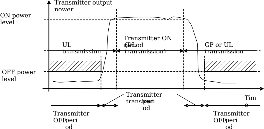
Figure 6.4.2.1-1: Example of relations between transmitter ON period, transmitter OFF period and transmitter transient period
For BS type 1-C this requirement shall be applied at the antenna connector supporting transmission in the operating band .
For BS type 1-H this requirement shall be applied at each TAB connector supporting transmission in the operating band.
6.4.2.2 Minimum requirement for BS type 1-C and BS type 1-H
For BS type 1-C and BS type 1-H , the transmitter transient period shall be shorter than the values listed in the minimum requirement table 6.4.2.2-1.
Table 6.4.2.2-1: Minimum requirement for the transmitter transient period for BS type 1-C and BS type 1-H
| Transition | Transient period length (µs) |
|---|---|
| OFF to ON | 10 |
| ON to OFF | 10 |
6.4.2.3 Void
6.5 Transmitted signal quality
6.5.1 Frequency error
6.5.1.1 General
The requirements in clause 6.5.1 apply to the transmitter ON period .
Frequency error is the measure of the difference between the actual BS transmit frequency and the assigned frequency. The same source shall be used for RF frequency and data clock generation.
For BS type 1-C this requirement shall be applied at the antenna connector supporting transmission in the operating band .
For BS type 1-H this requirement shall be applied at each TAB connector supporting transmission in the operating band.
6.5.1.2 Minimum requirement for BS type 1-C and BS type 1-H
For BS type 1-C and BS type 1-H, the modulated carrier frequency of each NR carrier configured by the BS shall be accurate to within the accuracy range given in table 6.5.1.2-1 observed over 1 ms.
The frequency error requirement for NB-IoT are specified in TS 36.104 [13] clause 6.5.1.
Table 6.5.1.2-1: Frequency error minimum requirement
| BS class | Accuracy |
|---|---|
| Wide Area BS | ±0.05 ppm |
| Medium Range BS | ±0.1 ppm |
| Local Area BS | ±0.1 ppm |
6.5.2 Modulation quality
6.5.2.1 General
Modulation quality is defined by the difference between the measured carrier signal and an ideal signal. Modulation quality can e.g. be expressed as Error Vector Magnitude (EVM). The Error Vector Magnitude is a measure of the difference between the ideal symbols and the measured symbols after the equalization. This difference is called the error vector. Details about how the EVM is determined are specified in Annex B.
For BS type 1-C this requirement shall be applied at the antenna connector supporting transmission in the operating band .
For BS type 1-H this requirement shall be applied at each TAB connector supporting transmission in the operating band.
NOTE: LP-WUS signal transmitting signal quality is assured in NR BS with NR signal transmission.
6.5.2.2 Minimum Requirement for BS type 1-C and BS type 1-H
For BS type 1-C and 1-H , the EVM levels of each NR carrier for different modulation schemes on PDSCH outlined in table 6.5.2.2-1 shall be met using the frame structure described in clause 6.5.2.3.
Table 6.5.2.2-1: EVM requirements for BS type 1-C and BS type 1-H carrier
| Modulation scheme for PDSCH | Required EVM |
|---|---|
| QPSK | 17.5 % |
| 16QAM | 12.5 % |
| 64QAM | 8 % |
| 256QAM | 3.5 % |
| 1024QAM | 2.5 % 1 2.8 % 2 |
| Note1: This requirement is applicable for frequencies equal to or below 4.2 GHz. Note 2: This requirement is applicable for frequencies above 4.2 GHz. |
The modulation quality requirements for NB-IoT are specified in TS 36.104 [13] clause 6.5.2.
6.5.2.3 EVM frame structure for measurement
EVM shall be evaluated for each NR carrier over all allocated resource blocks and downlink subframes. Different modulation schemes listed in table 6.5.2.2-1 shall be considered for rank 1.
For NR, for all bandwidths, the EVM measurement shall be performed for each NR carrier over all allocated resource blocks and downlink subframes within 10 ms measurement periods. The boundaries of the EVM measurement periods need not be aligned with radio frame boundaries.
6.5.3 Time alignment error
6.5.3.1 General
This requirement shall apply to frame timing in MIMO transmission, carrier aggregation and their combinations.
Frames of the NR signals present at the BS transmitter antenna connectors or TAB connectors are not perfectly aligned in time. The RF signals present at the BS transmitter antenna connectors or transceiver array boundary may experience certain timing differences in relation to each other.
The TAE is specified for a specific set of signals/transmitter configuration/transmission mode.
For BS type 1-C , the TAE is defined as the largest timing difference between any two signals belonging to different antenna connectors for a specific set of signals/transmitter configuration/transmission mode.
For BS type 1-H , the TAE is defined as the largest timing difference between any two signals belonging to TAB connectors belonging to different transmitter groups at the transceiver array boundary , where transmitter groups are associated with the TAB connectors in the transceiver unit array corresponding to MIMO transmission, carrier aggregation for a specific set of signals/transmitter configuration/transmission mode.
6.5.3.2 Minimum requirement for BS type 1-C and BS type 1-H
For MIMO transmission, at each carrier frequency, TAE shall not exceed 65 ns.
For intra-band contiguous carrier aggregation , with or without MIMO, TAE shall not exceed 260ns.
For intra-band non-contiguous carrier aggregation , with or without MIMO, TAE shall not exceed 3µs.
For inter-band carrier aggregation , with or without MIMO, TAE shall not exceed 3µs.
The time alignment error requirements for NB-IoT are specified in TS 36.104 [13] clause 6.5.3.
Table 6.5.3.2-1: Void
Table 6.5.3.2-2: Void
Table 6.5.3.2-3: Void
6.6 Unwanted emissions
6.6.1 General
Unwanted emissions consist of out-of-band emissions and spurious emissions according to ITU definitions [2]. In ITU terminology, out of band emissions are unwanted emissions immediately outside the BS channel bandwidth resulting from the modulation process and non-linearity in the transmitter but excluding spurious emissions. Spurious emissions are emissions which are caused by unwanted transmitter effects such as harmonics emission, parasitic emission, intermodulation products and frequency conversion products, but exclude out of band emissions.
The out-of-band emissions requirement for the BS transmitter is specified both in terms of Adjacent Channel Leakage power Ratio (ACLR) and operating band unwanted emissions (OBUE).
The maximum offset of the operating band unwanted emissions mask from the operating band edge is Δf OBUE . The Operating band unwanted emissions define all unwanted emissions in each supported downlink operating band plus the frequency ranges Δf OBUE above and Δf OBUE below each band. Unwanted emissions outside of this frequency range are limited by a spurious emissions requirement.
The values of Δf OBUE are defined in table 6.6.1-1 for the NR operating bands .
Table 6.6.1-1: Maximum offset of OBUE outside the downlink operating band
| BS type | Operating band characteristics | Δf OBUE (MHz) |
|---|---|---|
| BS type 1-H | F DL,high – F DL,low < 100 MHz | 10 |
| 100 MHz F DL,high – F DL,low 900 MHz | 40 | |
| BS type 1-C | F DL,high – F DL,low 200 MHz | 10 |
| 200 MHz < F DL,high – F DL,low 900 MHz | 40 | |
For band n46, n96 and n102, the values of Δf OBUE are defined in table 6.6.1-1a.
Table 6.6.1-1a: Maximum offset of OBUE outside the downlink operating band for band n46, n96 and n102
| Operating band | Δf OBUE (MHz) |
|---|---|
| n46, n102 | 40 |
| n96 | 50 |
For band n104, the values of Δf OBUE are defined in table 6.6.1-1b.
Table 6.6.1-1b: Maximum offset of OBUE outside the downlink operating band for band n104
| BS type | Operating band | Δf OBUE (MHz) |
|---|---|---|
| BS type 1-H | n104 | 100 |
| BS type 1-C | n104 | 40 |
For BS type 1-H the unwanted emission requirements are applied per the TAB connector TX min cell groups for all the configurations supported by the BS. The basic limits and corresponding emissions scaling are defined in each relevant clause.
There is in addition a requirement for occupied bandwidth.
6.6.2 Occupied bandwidth
6.6.2.1 General
The occupied bandwidth is the width of a frequency band such that, below the lower and above the upper frequency limits, the mean powers emitted are each equal to a specified percentage /2 of the total mean transmitted power. See also Recommendation ITU-R SM.328 [3].
The value of /2 shall be taken as 0.5%.
The occupied bandwidth requirement shall apply during the transmitter ON period for a single transmitted carrier. The minimum requirement below may be applied regionally. There may also be regional requirements to declare the occupied bandwidth according to the definition in the present clause.
For BS type 1-C this requirement shall be applied at the antenna connector supporting transmission in the operating band .
For BS type 1-H this requirement shall be appliedat each TAB connector supporting transmission in the operating band.
6.6.2.2 Minimum requirement for BS type 1-C and BS type 1-H
The occupied bandwidth for each NR carrier shall be less than the BS channel bandwidth . For intra-band contiguous CA, the occupied bandwidth shall be less than or equal the Aggregated BS Channel Bandwidth .
For NB.IoT operation in NR in-band, the occupied bandwidth for each NR carrier with NB-IoT shall be less than than the BS channel bandwidth .
If the BS supports LP-WUS operation, the occupied bandwidth for each NR carrier with LP-WUS shall be less than the BS channel bandwidth .
6.6.3 Adjacent Channel Leakage Power Ratio
6.6.3.1 General
Adjacent Channel Leakage power Ratio (ACLR) is the ratio of the filtered mean power centred on the assigned channel frequency to the filtered mean power centred on an adjacent channel frequency.
The requirements shall apply outside the Base Station RF Bandwidth or Radio Bandwidth whatever the type of transmitter considered (single carrier or multi-carrier) and for all transmission modes foreseen by the manufacturer’s specification.
The requirements shall also apply if the BS supports NB-IoT operation in NR in-band.
The requirements shall also apply if the BS supports LP-WUS operation.
For a BS operating in non-contiguous spectrum , the ACLR or the CACLR requirement in Tables 6.6.3.2-2a to 6.6.3.2-3aa shall apply in sub-block gaps , depending on the operating band and the sub-block gap size (W gap ) where the limit applies.
For a multi-band connector , the ACLR or the CACLR requirement in Tables 6.6.3.2-2a to 6.6.3.2-3aa shall apply in Inter RF Bandwidth gaps , depending on the operating band and the Inter RF Bandwidth gap size (W gap ) where the limit applies.
The requirement shall apply during the transmitter ON period .
6.6.3.2 Limits and Basic limits
The ACLR is defined with a square filter of bandwidth equal to the transmission bandwidth configuration of the transmitted signal (BW Config ) centred on the assigned channel frequency and a filter centred on the adjacent channel frequency according to the tables below.
For operation in paired and unpaired spectrum, the ACLR shall be higher than the value specified in table 6.6.3.2-1 in any operating band except for band n46, n96 and n102.
Table 6.6.3.2-1: Base station ACLR limit
| BS channel bandwidth of lowest/highest carrier transmitted BW Channel (MHz) | BS adjacent channel centre frequency offset below the lowest or above the highest carrier centre frequency transmitted | Assumed adjacent channel carrier (informative) | Filter on the adjacent channel frequency and corresponding filter bandwidth | ACLR limit |
|---|---|---|---|---|
| FR1 channel bandwidth as defined in Table 5.3.2-1 | BW Channel | NR of same BW (Note 2) | Square (BW Config ) | 45 dB, 38 dB (Note 4) |
| 2 x BW Channel | NR of same BW (Note 2) | Square (BW Config ) | 45 dB, 38 dB (Note 4) | |
| BW Channel /2 + 2.5 MHz | 5 MHz E-UTRA | Square (4.5 MHz) | 45 dB (Note 3) | |
| BW Channel /2 + 7.5 MHz | 5 MHz E-UTRA | Square (4.5 MHz) | 45 dB (Note 3) | |
| NOTE 1: BW Channel and BW Config are the BS channel bandwidth and transmission bandwidth configuration of the lowest/highest carrier transmitted on the assigned channel frequency. NOTE 2: With SCS that provides largest transmission bandwidth configuration (BW Config ). NOTE 3: The requirements are applicable when the band is also defined for E-UTRA or UTRA. NOTE 4: For BS operating in band n104, ACLR requirement 38 dB applies. For BS operating in other bands, ACLR requirement 45 dB applies. |
For band n46, n96 and n102, the ACLR shall be higher than the value specified in Table 6.6.3.2-1a.
Table 6.6.3.2-1a: Base station ACLR limit for band n46, n96 and n102
| BS channel bandwidth of lowest/highest NR carrier transmitted BW Channel (MHz) | BS adjacent channel centre frequency offset below the lowest or above the highest carrier centre frequency transmitted | Assumed adjacent channel carrier (informative) | Filter on the adjacent channel frequency and corresponding filter bandwidth | ACLR limit |
|---|---|---|---|---|
| 10, 20, 40, 60, 80 | BW Channel | NR of same BW (Note 2) | Square (BW Config ) | 35 dB |
| 2 x BW Channel | NR of same BW (Note 2) | Square (BW Config ) | 40 dB | |
| NOTE 1: BW Channel and BW Config are the BS channel bandwidth and transmission bandwidth configuration of the lowest/highest NR carrier transmitted on the assigned channel frequency. NOTE 2: With SCS that provides largest transmission bandwidth configuration (BW Config ). |
The ACLR absolute basic limit is specified in table 6.6.3.2-2.
Table 6.6.3.2-2: Base station ACLR absolute basic limit
| BS category / BS class | ACLR absolute basic limit |
|---|---|
| Category A Wide Area BS | -13 dBm/MHz |
| Category B Wide Area BS | -15 dBm/MHz |
| Medium Range BS | -25 dBm/MHz |
| Local Area BS | -32 dBm/MHz |
For operation in non-contiguous spectrum or multiple bands, the ACLR shall be higher than the value specified in Table 6.6.3.2-2a in any operating band except for band n46, n96 and n102.
Table 6.6.3.2-2a: Base Station ACLR limit in non-contiguous spectrum or multiple bands
| BS channel bandwidth of carrier transmitted BW Channel adjacent to s ub-block gap or inter RF Bandwidth gap (MHz) | Sub-block or Inter RF Bandwidth gap size (W gap ) where the limit applies (MHz) | BS adjacent channel centre frequency offset below or above the sub-block or Base Station RF Bandwidth edge (inside the gap) | Assumed adjacent channel carrier | Filter on the adjacent channel frequency and corresponding filter bandwidth | ACLR limit |
|---|---|---|---|---|---|
| 3, 5, 7, 10, 15, 20 | W gap ≥ 15 (Note 3) W gap ≥ 45 (Note 4) | 2.5 MHz | 5 MHz NR (Note 2) | Square (BW Config ) | 45 dB, 38 dB (Note 5) |
| W gap ≥ 20 (Note 3) W gap ≥ 50 (Note 4) | 7.5 MHz | 5 MHz NR (Note 2) | Square (BW Config ) | 45 dB, 38 dB (Note 5) | |
| 25, 30, 35, 40, 45, 50, 60, 70, 80, 90, 100 | W gap ≥ 60 (Note 4) W gap ≥ 30 (Note 3) | 10 MHz | 20 MHz NR (Note 2) | Square (BW Config ) | 45 dB, 38 dB (Note 5) |
| W gap ≥ 80 (Note 4) W gap ≥ 50 (Note 3) | 30 MHz | 20 MHz NR (Note 2) | Square (BW Config ) | 45 dB, 38 dB (Note 5) | |
| NOTE 1: BW Config is the transmission bandwidth configuration of the assumed adjacent channel carrier. NOTE 2: With SCS that provides largest transmission bandwidth configuration (BW Config ). NOTE 3: Applicable in case the BS channel bandwidth of the NR carrier transmitted at the other edge of the gap is 3, 5, 7, 10, 15, 20 MHz. NOTE 4: Applicable in case the BS channel bandwidth of the NR carrier transmitted at the other edge of the gap is 25, 30, 35, 40, 45, 50, 60, 70, 80, 90, 100 MHz. NOTE 5: For BS operating in band n104, ACLR requirement 38 dB applies. For BS operating in other bands, ACLR requirement 45 dB applies. |
For operation in non-contiguous spectrum for band n46, n96 and n102, the ACLR shall be higher than the value specified in Table 6.6.3.2-2b.
Table 6.6.3.2-2b: Base Station ACLR limit in non-contiguous spectrum for band n46, n96 and n102
| BS channel bandwidth of NR carrier transmitted BW Channel adjacent to s ub-block gap or inter RF Bandwidth gap (MHz) | Sub-block or Inter RF Bandwidth gap size (W gap ) where the limit applies (MHz) | BS adjacent channel centre frequency offset below or above the sub-block or Base Station RF Bandwidth edge (inside the gap) | Assumed adjacent channel carrier | Filter on the adjacent channel frequency and corresponding filter bandwidth | ACLR limit |
|---|---|---|---|---|---|
| 10, 20, 40, 60, 80 | W gap ≥ 60 | 10 MHz | 20 MHz NR (Note 2) | Square (BW Config ) | 35 dB |
| W gap ≥ 80 | 30 MHz | 20 MHz NR (Note 2) | Square (BW Config ) | 40 dB | |
| NOTE 1: BW Config is the transmission bandwidth configuration of the assumed adjacent channel carrier. NOTE 2: With SCS that provides largest transmission bandwidth configuration (BW Config ). |
The Cumulative Adjacent Channel Leakage power Ratio (CACLR) in a sub-block gap or the Inter RF Bandwidth gap is the ratio of:
a) the sum of the filtered mean power centred on the assigned channel frequencies for the two carriers adjacent to each side of the sub-block gap or the Inter RF Bandwidth gap , and
b) the filtered mean power centred on a frequency channel adjacent to one of the respective sub-block edges or Base Station RF Bandwidth edges .
The assumed filter for the adjacent channel frequency is defined in table 6.6.3.2-3 and the filters on the assigned channels are defined in table 6.6.3.2-4.
For operation in non-contiguous spectrum or multiple bands, the CACLR for NR carriers located on either side of the sub-block gap or the Inter RF Bandwidth gap shall be higher than the value specified in table 6.6.3.2-3.
The CACLR requirements in Table 6.6.3.2-3 apply to BS that supports NR, in any operating band except for band n46, n96 and n102. The CACLR requirements for band n46, n96 and n102 are in Table 6.6.3.2-3aa.
Table 6.6.3.2-3: Base Station CACLR limit
| BS channel bandwidth of carrier transmitted BW Channel adjacent to s ub-block gap or inter RF Bandwidth gap (MHz) | Sub-block or Inter RF Bandwidth gap size (W gap ) where the limit applies (MHz) | BS adjacent channel centre frequency offset below or above the sub-block or Base Station RF Bandwidth edge (inside the gap) | Assumed adjacent channel carrier | Filter on the adjacent channel frequency and corresponding filter bandwidth | CACLR limit |
|---|---|---|---|---|---|
| 3, 5, 7, 10, 15, 20 | 5 ≤W gap < 15 (Note 3) 5 ≤W gap < 45 (Note 4) | 2.5 MHz | 5 MHz NR (Note 2) | Square (BW Config ) | 45 dB, 38 dB (Note 5) |
| 10 < W gap < 20 (Note 3) 10 ≤W gap < 50 (Note 4) | 7.5 MHz | 5 MHz NR (Note 2) | Square (BW Config ) | 45 dB, 38 dB (Note 5) | |
| 25, 30, 35, 40, 45, 50, 60, 70, 80,90, 100 | 20 ≤W gap < 60 (Note 4) 20 ≤W gap < 30 (Note 3) | 10 MHz | 20 MHz NR (Note 2) | Square (BW Config ) | 45 dB, 38 dB (Note 5) |
| 40 < W gap < 80 (Note 4) 40 ≤W gap < 50 (Note 3) | 30 MHz | 20 MHz NR (Note 2) | Square (BW Config ) | 45 dB, 38 dB (Note 5) | |
| NOTE 1: BW Config is the transmission bandwidth configuration of the assumed adjacent channel carrier. NOTE 2: With SCS that provides largest transmission bandwidth configuration (BW Config ). NOTE 3: Applicable in case the BS channel bandwidth of the NR carrier transmitted at the other edge of the gap is 3, 5, 7, 10, 15, 20 MHz. NOTE 4: Applicable in case the BS channel bandwidth of the NR carrier transmitted at the other edge of the gap is 25, 30, 35, 40, 45, 50, 60, 70, 80, 90, 100 MHz. NOTE 5: For BS operating in band n104, ACLR requirement 38 dB applies. For BS operating in other bands, ACLR requirement 45 dB applies. |
For operation in non-contiguous spectrum for band n46, n96 and n102, the CACLR for NR carriers located on either side of the sub-block gap shall be higher than the value specified in Table 6.6.3.2-3aa.
Table 6.6.3.2-3aa: Base Station CACLR limit for band n46, n96 and n102
| BS channel bandwidth of NR carrier transmitted BW Channel adjacent to s ub-block gap or inter RF Bandwidth gap (MHz) | Sub-block or Inter RF Bandwidth gap size (W gap ) where the limit applies (MHz) | BS adjacent channel centre frequency offset below or above the sub-block or Base Station RF Bandwidth edge (inside the gap) | Assumed adjacent channel carrier | Filter on the adjacent channel frequency and corresponding filter bandwidth | CACLR limit |
|---|---|---|---|---|---|
| 10, 20, 40, 60, 80 | 20 ≤W gap < 60 | 10 MHz | 20 MHz NR (Note 2) | Square (BW Config ) | 35 dB |
| 40 < W gap < 80 | 30 MHz | 20 MHz NR (Note 2) | Square (BW Config ) | 40 dB | |
| NOTE 1: BW Config is the transmission bandwidth configuration of the assumed adjacent channel carrier. NOTE 2: With SCS that provides largest transmission bandwidth configuration (BW Config ). |
The CACLR absolute basic limit is specified in table 6.6.3.2-3a.
Table 6.6.3.2-3a: Base station CACLR absolute basic limit
| BS category / BS class | CACLR absolute basic limit |
|---|---|
| Category A Wide Area BS | -13 dBm/MHz |
| Category B Wide Area BS | -15 dBm/MHz |
| Medium Range BS | -25 dBm/MHz |
| Local Area BS | -32 dBm/MHz |
Table 6.6.3.2-4: Filter parameters for the assigned channel
| RAT of the carrier adjacent to the sub-block or Inter RF Bandwidth gap | Filter on the assigned channel frequency and corresponding filter bandwidth |
|---|---|
| NR | NR of same BW with SCS that provides largest transmission bandwidth configuration |
6.6.3.3 Minimum requirement for BS type 1-C
The ACLR (CACLR) absolute basic limits in table 6.6.3.2-2, 6.6.3.2-3a or the ACLR (CACLR) limits in table 6.6.3.2-1, 6.6.3.2-2a or 6.6.3.2-3, whichever is less stringent, shall apply for each antenna connector .
For Band n41 and n90 operation in Japan, absolute ACLR limits shall be applied to the sum of the absolute ACLR power over all antenna connectors for BS type 1-C .
6.6.3.4 Minimum requirement for BS type 1-H
The ACLR (CACLR) absolute basic limits in table 6.6.3.2-2 + X, 6.6.3.2-3a + X (where X = 10log 10 (N TXU,countedpercell )) or the ACLR (CACLR) limits in table 6.6.3.2-1, 6.6.3.2-2a or 6.6.3.2-3, whichever is less stringent, shall apply for each TAB connector TX min cell group .
NOTE: Conformance to the BS type 1-H ACLR requirement can be demonstrated by meeting at least one of the following criteria as determined by the manufacturer:
- The ratio of the sum of the filtered mean power measured on each TAB connector in the TAB connector TX min cell group at the assigned channel frequency to the sum of the filtered mean power measured on each TAB connector in the TAB connector TX min cell group at the adjacent channel frequency shall be greater than or equal to the ACLR basic limit of the BS. This shall apply for each TAB connector TX min cell group .
Or
- The ratio of the filtered mean power at the TAB connector centred on the assigned channel frequency to the filtered mean power at this TAB connector centred on the adjacent channel frequency shall be greater than or equal to the ACLR basic limit of the BS for every TAB connector in the TAB connector TX min cell group , for each TAB connector TX min cell group .
In case the ACLR (CACLR) absolute basic limit of BS type 1-H are applied, the conformance can be demonstrated by meeting at least one of the following criteria as determined by the manufacturer:
- The sum of the filtered mean power measured on each TAB connector in the TAB connector TX min cell group at the adjacent channel frequency shall be less than or equal to the ACLR (CACLR) absolute ba sic limit + X of the BS. This shall apply to each TAB connector TX min cell group.
Or
- The filtered mean power at each TAB connector centred on the adjacent channel frequency shall be less than or equal to the ACLR (CACLR) absolute basic limit of the BS scaled by X -10log 10 ( n ) for every TAB connector in the TAB connector TX min cell group , for each TAB connector TX min cell group , where n is the number of TAB connectors in the TAB connector TX min cell group.
6.6.4 Operating band unwanted emissions
6.6.4.1 General
Unless otherwise stated, the operating band unwanted emission (OBUE) limits in FR1 are defined from Δf OBUE below the lowest frequency of each supported downlink operating band up to Δf OBUE above the highest frequency of each supported downlink operating band . The values of Δf OBUE are defined in table 6.6.1-1 for the NR operating bands .
The requirements shall apply whatever the type of transmitter considered and for all transmission modes foreseen by the manufacturer’s specification. In addition, for a BS operating in non-contiguous spectrum , the requirements apply inside any sub-block gap . In addition, for a BS operating in multiple bands, the requirements apply inside any Inter RF Bandwidth gap .
Basic limits are specified in the tables below, where:
-
f is the separation between the channel edge frequency and the nominal -3dB point of the measuring filter closest to the carrier frequency.
-
f_offset is the separation between the channel edge frequency and the centre of the measuring filter.
-
f_offset max is the offset to the frequency Δf OBUE outside the downlink operating band , where Δf OBUE is defined in table 6.6.1-1.
-
f max is equal to f_offset max minus half of the bandwidth of the measuring filter.
For a multi-band connector inside any Inter RF Bandwidth gaps with W gap < 2*Δf OBUE , a combined basic limit shall be applied which is the cumulative sum of the basic limit s specified at the Base Station RF Bandwidth edges on each side of the Inter RF Bandwidth gap . The basic limit for Base Station RF Bandwidth edge is specified in clauses 6.6.4.2.1 to 6.6.4.2.4 below, where in this case:
-
f is the separation between the Base Station RF Bandwidth edge frequency and the nominal -3 dB point of the measuring filter closest to the Base Station RF Bandwidth edge .
-
f_offset is the separation between the Base Station RF Bandwidth edge frequency and the centre of the measuring filter.
-
f_offset max is equal to the Inter RF Bandwidth gap minus half of the bandwidth of the measuring filter.
-
f max is equal to f_offset max minus half of the bandwidth of the measuring filter.
For a multi-band connector , the operating band unwanted emission limits apply also in a supported operating band without any carrier transmitted, in the case where there are carrier(s) transmitted in another supported operating band . In this case, no cumulative basic limit is applied in the inter-band gap between a supported downlink operating band with carrier(s) transmitted and a supported downlink operating band without any carrier transmitted and
-
In case the inter-band gap between a supported downlink operating band with carrier(s) transmitted and a supported downlink operating band without any carrier transmitted is less than 2*Δf OBUE , f_offset max shall be the offset to the frequency Δf OBUE MHz outside the outermost edges of the two supported downlink operating bands and the operating band unwanted emission basic limits of the band where there are carriers transmitted, as defined in the tables of the present clause, shall apply across both downlink bands.
-
In other cases, the operating band unwanted emission basic limits of the band where there are carriers transmitted, as defined in the tables of the present clause for the largest frequency offset (f max ), shall apply from Δf OBUE MHz below the lowest frequency, up to Δf OBUE MHz above the highest frequency of the supported downlink operating band without any carrier transmitted.
For a multi-carrier single-band connector or a single-band connector configured for intra-band contiguous or non-contiguous carrier aggregation the definitions above apply to the lower edge of the carrier transmitted at the lowest carrier frequency and the upper edge of the carrier transmitted at the highest carrier frequency within a specified frequency band.
In addition, inside any sub-block gap for a single-band connector operating in non-contiguous spectrum , a combined basic limit shall be applied which is the cumulative sum of the basic limit s specified for the adjacent sub-blocks on each side of the sub-block gap . The basic limit for each sub-block is specified in clauses 6.6.4.2.1 to 6.6.4.2.4 below, where in this case:
-
f is the separation between the sub-block edge frequency and the nominal -3 dB point of the measuring filter closest to the sub-block edge.
-
f_offset is the separation between the sub-block edge frequency and the centre of the measuring filter.
-
f_offset max is equal to the sub-block gap bandwidth minus half of the bandwidth of the measuring filter.
-
f max is equal to f_offset max minus half of the bandwidth of the measuring filter.
For Wide Area BS, the requirements of either clause 6.6.4.2.1 (Category A limits) or clause 6.6.4.2.2 (Category B limits) shall apply.
For Medium Range BS, the requirements in clause 6.6.4.2.3 shall apply (Category A and B).
For Local Area BS, the requirements of clause 6.6.4.2.4 shall apply (Category A and B).
The requirements shall also apply if the BS supports NB-IoT operation in NR in-band.
The requirements shall also apply if the BS supports LP-WUS operation.
The application of either Category A or Category B basic limits shall be the same as for Transmitter spurious emissions in clause 6.6.5.
6.6.4.2 Basic limits
6.6.4.2.1 Basic limits for Wide Area BS (Category A)
For BS operating in Bands n5, n8, n12, n13, n14, n18, n26, n28, n29, n31, n68, n71, n72, n85, n87, n88, n105, n106, basic limits are specified in tables 6.6.4.2.1-1 and 6.6.4.2.1-1a.
Table 6.6.4.2.1-1: Wide Area BS operating band unwanted emission limits for above 3 MHz channel bandwidth (NR bands below 1 GHz) for Category A
| Frequency offset of measurement filter -3dB point, f | Frequency offset of measurement filter centre frequency, f_offset | Basic limits (Note 1, 2) | Measurement bandwidth |
|---|---|---|---|
| 0 MHz f < 5 MHz | 0.05 MHz f_offset < 5.05 MHz |  |
100 kHz |
| 5 MHz f < min(10 MHz, f max ) | 5.05 MHz f_offset < min(10.05 MHz, f_offset max ) | -14 dBm | 100 kHz |
| 10 MHz f f max | 10.05 MHz f_offset < f_offset max | -13 dBm (Note 3) | 100 kHz |
| NOTE 1: For a BS supporting non-contiguous spectrum operation within any operating band , the emission limits within sub-block gaps is calculated as a cumulative sum of contributions from adjacent sub-blocks on each side of the sub-block gap . Exception is f ≥ 10MHz from both adjacent sub-blocks on each side of the sub-block gap , where the emission limits within sub-block gaps shall be -13 dBm/100 kHz. NOTE 2: For a multi-band connector with Inter RF Bandwidth gap < 2*Δf OBUE the emission limits within the Inter RF Bandwidth gap s is calculated as a cumulative sum of contributions from adjacent sub-blocks or RF Bandwidth on each side of the Inter RF Bandwidth gap . NOTE 3: The requirement is not applicable when f max < 10 MHz. |
Table 6.6.4.2.1-1a: Wide Area BS operating band unwanted emission limits for 3 MHz channel bandwidth (NR bands below 1 GHz) for Category A
| Frequency offset of measurement filter -3dB point, f | Frequency offset of measurement filter centre frequency, f_offset | Basic limits (Note 1, 2) | Measurement bandwidth |
|---|---|---|---|
| 0 MHz f < 3 MHz | 0.05 MHz f_offset < 3.05 MHz |  |
100 kHz |
| 3 MHz f < 6 MHz | 3.05 MHz f_offset < 6.05 MHz | -15 dBm | 100 kHz |
| 6 MHz f f max | 6.05 MHz f_offset < f_offset max | -13 dBm | 100 kHz |
| NOTE 1: For a BS supporting non-contiguous spectrum operation within any operating band , the emission limits within sub-block gaps is calculated as a cumulative sum of contributions from adjacent sub-blocks on each side of the sub-block gap . Exception is f ≥ 6MHz from both adjacent sub-blocks on each side of the sub-block gap , where the emission limits within sub-block gaps shall be -13 dBm/100 kHz. NOTE 2: For a multi-band connector with Inter RF Bandwidth gap < 2*Δf OBUE the emission limits within the Inter RF Bandwidth gap s is calculated as a cumulative sum of contributions from adjacent sub-blocks or RF Bandwidth on each side of the Inter RF Bandwidth gap . |
For BS operating in Bands n1, n2, n3, n7, n24, n25, n30, n34, n38, n39, n40, n41, n48, n50, n54, n65, n66, n70, n74, n75, n77, n78, n79, n90, n92, n94, n109, n110, n115, basic limits are specified in table 6.6.4.2.1-2 and 6.6.4.2.1-2a:
Table 6.6.4.2.1-2: Wide Area BS operating band unwanted emission limits for above 3 MHz channel bandwidth (NR bands above 1 GHz) for Category A
| Frequency offset of measurement filter -3dB point, f | Frequency offset of measurement filter centre frequency, f_offset | Basic limits (Note 1, 2) | Measurement bandwidth |
|---|---|---|---|
| 0 MHz f < 5 MHz | 0.05 MHz f_offset < 5.05 MHz | |
100 kHz |
| 5 MHz f < min(10 MHz, f max ) | 5.05 MHz f_offset < min(10.05 MHz, f_offset max ) | -14 dBm | 100 kHz |
| 10 MHz f f max | 10.5 MHz f_offset < f_offset max | -13 dBm (Note 3) | 1MHz |
| NOTE 1: For a BS supporting non-contiguous spectrum operation within any operating band , the emission limits within sub-block gaps is calculated as a cumulative sum of contributions from adjacent sub-blocks on each side of the sub-block gap , where the contribution from the far-end sub-block shall be scaled according to the measurement bandwidth of the near-end sub-block . Exception is f ≥ 10MHz from both adjacent sub-blocks on each side of the sub-block gap , where the emission limits within sub-block gaps shall be -13 dBm/1 MHz. NOTE 2: For a multi-band connector with Inter RF Bandwidth gap < 2*Δf OBUE the emission limits within the Inter RF Bandwidth gaps is calculated as a cumulative sum of contributions from adjacent sub-blocks or RF Bandwidth on each side of the Inter RF Bandwidth gap , where the contribution from the far-end sub-block or RF Bandwidth shall be scaled according to the measurement bandwidth of the near-end sub-block or RF Bandwidth. NOTE 3: The requirement is not applicable when f max < 10 MHz. |
Table 6.6.4.2.1-2a: Wide Area BS operating band unwanted emission limits for 3 MHz channel bandwidth (NR bands above 1 GHz) for Category A
| Frequency offset of measurement filter -3dB point, f | Frequency offset of measurement filter centre frequency, f_offset | Basic limits (Note 1, 2) | Measurement bandwidth |
|---|---|---|---|
| 0 MHz f < 3 MHz | 0.05 MHz f_offset < 3.05 MHz | |
100 kHz |
| 3 MHz f < 6 MHz | 3.05 MHz f_offset < 6.05 MHz | -15 dBm | 100 kHz |
| 6 MHz f f max | 6.05 MHz f_offset < f_offset max | -13 dBm | 1 MHz |
| NOTE 1: For a BS supporting non-contiguous spectrum operation within any operating band , the emission limits within sub-block gaps is calculated as a cumulative sum of contributions from adjacent sub-blocks on each side of the sub-block gap . Exception is f ≥ 6MHz from both adjacent sub-blocks on each side of the sub-block gap , where the emission limits within sub-block gaps shall be -13 dBm/100 kHz. NOTE 2: For a multi-band connector with Inter RF Bandwidth gap < 2*Δf OBUE the emission limits within the Inter RF Bandwidth gap s is calculated as a cumulative sum of contributions from adjacent sub-blocks or RF Bandwidth on each side of the Inter RF Bandwidth gap . |
6.6.4.2.2 Basic limits for Wide Area BS (Category B)
For Category B Operating band unwanted emissions, there are two options for the basic limits that may be applied regionally. Either the basic limits in clause 6.6.4.2.2.1 or clause 6.6.4.2.2.2 shall be applied.
6.6.4.2.2.1 Category B requirements (Option 1)
For BS operating in Bands n5, n8, n12, n20, n26, n28, n29, n31, n67, n68, n71, n72, n85, n87, n88, n105, the basic limits are specified in tables 6.6.4.2.2.1-1 and 6.6.4.2.2.1-1a.:
Table 6.6.4.2.2.1-1: Wide Area BS operating band unwanted emission limits for above 3 MHz channel bandwidth(NR bands below 1 GHz) for Category B
| Frequency offset of measurement filter -3dB point, f | Frequency offset of measurement filter centre frequency, f_offset | Basic limits (Note 1, 2) | Measurement bandwidth |
|---|---|---|---|
| 0 MHz f < 5 MHz | 0.05 MHz f_offset < 5.05 MHz | |
100 kHz |
| 5 MHz f < min(10 MHz, f max ) | 5.05 MHz f_offset < min(10.05 MHz, f_offset max ) | -14 dBm | 100 kHz |
| 10 MHz f f max | 10.05 MHz f_offset < f_offset max | -16 dBm (Note 3) | 100 kHz |
| NOTE 1: For a BS supporting non-contiguous spectrum operation within any operating band , the emission limits within sub-block gaps is calculated as a cumulative sum of contributions from adjacent sub-blocks on each side of the sub-block gap . Exception is f ≥ 10MHz from both adjacent sub-blocks on each side of the sub-block gap , where the emission limits within sub-block gaps shall be -16 dBm/100 kHz. NOTE 2: For a multi-band connector with Inter RF Bandwidth gap < 2*Δf OBUE the emission limits within the Inter RF Bandwidth gaps is calculated as a cumulative sum of contributions from adjacent sub-blocks or RF Bandwidth on each side of the Inter RF Bandwidth gap , where the contribution from the far-end sub-block or RF Bandwidth shall be scaled according to the measurement bandwidth of the near-end sub-block or RF Bandwidth. NOTE 3: The requirement is not applicable when f max < 10 MHz. |
Table 6.6.4.2.2.1-1a: Wide Area BS operating band unwanted emission limits for 3 MHz channel bandwidth (NR bands below 1 GHz) for Category B
| Frequency offset of measurement filter -3dB point, f | Frequency offset of measurement filter centre frequency, f_offset | Basic limits (Note 1, 2) | Measurement bandwidth |
|---|---|---|---|
| 0 MHz f < 3 MHz | 0.05 MHz f_offset < 3.05 MHz | |
100 kHz |
| 3 MHz f < 6 MHz | 3.05 MHz f_offset < 6.05 MHz | -15 dBm | 100 kHz |
| 6 MHz f f max | 6.05 MHz f_offset < f_offset max | -16 dBm | 100 kHz |
| NOTE 1: For a BS supporting non-contiguous spectrum operation within any operating band , the emission limits within sub-block gaps is calculated as a cumulative sum of contributions from adjacent sub-blocks on each side of the sub-block gap . Exception is f ≥ 6MHz from both adjacent sub-blocks on each side of the sub-block gap , where the emission limits within sub-block gaps shall be -16 dBm/100 kHz. NOTE 2: For a multi-band connector with Inter RF Bandwidth gap < 2*Δf OBUE the emission limits within the Inter RF Bandwidth gaps is calculated as a cumulative sum of contributions from adjacent sub-blocks or RF Bandwidth on each side of the Inter RF Bandwidth gap , where the contribution from the far-end sub-block or RF Bandwidth shall be scaled according to the measurement bandwidth of the near-end sub-block or RF Bandwidth. |
For BS operating in Bands n1, n2, n3, n7, n25, n34, n38, n39, n40, n41, n48, n50, n65, n66, n70, n75, n77, n78, n79, n90, n92, n94, n109, basic limits are specified in tables 6.6.4.2.2.1-2:
Table 6.6.4.2.2.1-2: Wide Area BS operating band unwanted emission limits (NR bands above 1 GHz) for Category B
| Frequency offset of measurement filter -3dB point, f | Frequency offset of measurement filter centre frequency, f_offset | Basic limits (Note 1, 2) | Measurement bandwidth |
|---|---|---|---|
| 0 MHz f < 5 MHz | 0.05 MHz f_offset < 5.05 MHz | |
100 kHz |
| 5 MHz f < min(10 MHz, f max ) | 5.05 MHz f_offset < min(10.05 MHz, f_offset max ) | -14 dBm | 100 kHz |
| 10 MHz f f max | 10.5 MHz f_offset < f_offset max | -15 dBm (Note 3) | 1MHz |
| NOTE 1: For a BS supporting non-contiguous spectrum operation within any operating band , the emission limits within sub-block gaps is calculated as a cumulative sum of contributions from adjacent sub-blocks on each side of the sub-block gap , where the contribution from the far-end sub-block shall be scaled according to the measurement bandwidth of the near-end sub-block . Exception is f ≥ 10MHz from both adjacent sub-blocks on each side of the sub-block gap , where the emission limits within sub-block gaps shall be -15 dBm/1 MHz. NOTE 2: For a multi-band connector with Inter RF Bandwidth gap < 2*Δf OBUE the emission limits within the Inter RF Bandwidth gaps is calculated as a cumulative sum of contributions from adjacent sub-blocks or RF Bandwidth on each side of the Inter RF Bandwidth gap , where the contribution from the far-end sub-block or RF Bandwidth shall be scaled according to the measurement bandwidth of the near-end sub-block or RF Bandwidth. NOTE 3: The requirement is not applicable when f max < 10 MHz. |
For BS type 1-C operating in Band n104, the limits are specified in tables 6.6.4.2.2.1-2a:
Table 6.6.4.2.2.1-2a: Wide Area BS type 1-C operating band unwanted emission limits for band n104 for Category B
| Frequency offset of measurement filter -3dB point, f | Frequency offset of measurement filter centre frequency, f_offset | Basic limits | Measurement bandwidth |
|---|---|---|---|
| 0 MHz f < 20 MHz | 0.05 MHz f_offset < 20.05 MHz | 100 kHz | |
| 20 MHz f < min(40 MHz, f max ) | 20.05 MHz f_offset < min(40.05 MHz, f_offset max ) | -14 dBm | 100 kHz |
| 40 MHz f f max | 40.5 MHz f_offset < f_offset max | -15 dBm (Note 3) | 1MHz |
| NOTE 1: For a BS supporting non-contiguous spectrum operation within any operating band the emission limits within sub-block gaps is calculated as a cumulative sum of contributions from adjacent sub-blocks on each side of the sub-block gap . Exception is f ≥ 40MHz from both adjacent sub-blocks on each side of the sub-block gap , where the emission limits within sub-block gaps shall be -15 dBm/1 MHz. NOTE 2: For a multi-band connector with Inter RF Bandwidth gap < 2*Δf OBUE the emission limits within the Inter RF Bandwidth gaps is calculated as a cumulative sum of contributions from adjacent sub-blocks or RF Bandwidth on each side of the Inter RF Bandwidth gap . NOTE 3: The requirement is not applicable when f max <40 MHz. |
For BS type 1-H operating in Band n104, basic limits are specified in tables 6.6.4.2.2.1-2b:
Table 6.6.4.2.2.1-2b: Wide Area BS type 1-H operating band unwanted emission limits for band n104 for Category B
| Frequency offset of measurement filter -3dB point, f | Frequency offset of measurement filter centre frequency, f_offset | Basic limits | Measurement bandwidth |
|---|---|---|---|
| 0 MHz f < 50 MHz | 0.05 MHz f_offset < 50.05 MHz | 100 kHz | |
| 50 MHz f < min(100 MHz, f max ) | 50.05 MHz f_offset < min(100.05 MHz, f_offset max ) | -14 dBm | 100 kHz |
| 100 MHz f f max | 100.5 MHz f_offset < f_offset max | -15 dBm (Note 3) | 1MHz |
| NOTE 1: For a BS supporting non-contiguous spectrum operation within any operating band the emission limits within sub-block gaps is calculated as a cumulative sum of contributions from adjacent sub-blocks on each side of the sub-block gap . Exception is f ≥ 100MHz from both adjacent sub-blocks on each side of the sub-block gap , where the emission limits within sub-block gaps shall be -15 dBm/1 MHz. NOTE 2: For a multi-band connector with Inter RF Bandwidth gap < 2*Δf OBUE the emission limits within the Inter RF Bandwidth gaps is calculated as a cumulative sum of contributions from adjacent sub-blocks or RF Bandwidth on each side of the Inter RF Bandwidth gap . NOTE 3: The requirement is not applicable when f max < 100 MHz. |
6.6.4.2.2.2 Category B requirements (Option 2)
The limits in this clause are intended for Europe and may be applied regionally for BS operating in bands n1, n3, n7, n8, n38, n65, n100, n101.
For a BS operating in bands n1, n3, n8, n65 or BS type 1-C operating in bands n7, n38, n100 or n101, basic limits are specified in Tables 6.6.4.2.2.2-1 and 6.6.4.2.2.2-1a.:
Table 6.6.4.2.2.2-1: Regional Wide Area BS operating band unwanted emission limits for above 3 MHz channel bandwidth for Category B
| Frequency offset of measurement filter -3dB point, f | Frequency offset of measurement filter centre frequency, f_offset | Basic limits (Note 1, 2) | Measurement bandwidth |
|---|---|---|---|
| 0 MHz f < 0.2 MHz | 0.015 MHz f_offset < 0.215 MHz | -14 dBm | 30 kHz |
| 0.2 MHz f < 1 MHz | 0.215 MHz f_offset < 1.015 MHz | 30 kHz | |
| (Note 4) | 1.015 MHz f_offset < 1.5 MHz | -26 dBm (Note 5) | 30 kHz |
| 1 MHz f min( 10 MHz, f max ) | 1.5 MHz f_offset < min(10.5 MHz, f_offset max ) | -13 dBm (Note 5) | 1 MHz |
| 10 MHz f f max | 10.5 MHz f_offset < f_offset max | -15 dBm (Note 3) (Note 5) | 1 MHz |
| NOTE 1: For a BS supporting non-contiguous spectrum operation within any operating band , the minimum requirement within sub-block gaps is calculated as a cumulative sum of contributions from adjacent sub-blocks on each side of the sub-block gap , where the contribution from the far-end sub-block shall be scaled according to the measurement bandwidth of the near-end sub-block . Exception is f ≥ 10MHz from both adjacent sub-blocks on each side of the sub-block gap , where the minimum requirement within sub-block gaps shall be -15dBm/1MHz. For BS supporting multi-band operation, either this limit or -16dBm/100kHz (f_offset adjusted according to the measurement bandwidth), whichever is less stringent, shall apply at f ≥ 10MHz for operating bands <1GHz. NOTE 2: For a multi-band connector with Inter RF Bandwidth gap < 2*Δf OBUE the minimum requirement within the Inter RF Bandwidth gaps is calculated as a cumulative sum of contributions from adjacent sub-blocks or RF Bandwidth on each side of the Inter RF Bandwidth gap , where the contribution from the far-end sub-block or RF Bandwidth shall be scaled according to the measurement bandwidth of the near-end sub-block or RF Bandwidth. NOTE 3: The requirement is not applicable when f max < 10 MHz. NOTE 4: This frequency range ensures that the range of values of f_offset is continuous. NOTE 5: For BS supporting multi-band operation, either this limit or -16dBm/100kHz (f_offset adjusted according to the measurement bandwidth), whichever is less stringent, shall apply for operating bands <1GHz. |
Table 6.6.4.2.2.2-1a: Regional Wide Area BS operating band unwanted emission limits for 3 MHz channel bandwidth for Category B
| Frequency offset of measurement filter -3dB point, f | Frequency offset of measurement filter centre frequency, f_offset | Basic limits (Note 1, 2) | Measurement bandwidth |
|---|---|---|---|
| 0 MHz f < 0.05 MHz | 0.015 MHz f_offset < 0.065 MHz | 30 kHz | |
| 0.05 MHz f < 0.15 MHz | 0. 065 MHz f_offset < 0.165 MHz | 30 kHz | |
| 0.15 MHz f < 0.2 MHz | 0.165MHz f_offset < 0.215MHz | -14 dBm | 30 kHz |
| 0.2 MHz f < 1 MHz | 0.215MHz f_offset < 1.015MHz | 30 kHz | |
| (Note 3) | 1.015MHz f_offset < 1.5 MHz | -26 dBm | 30 kHz |
| 1 MHz f 6 MHz | 1.5 MHz f_offset < 6.5 MHz | -13 dBm | 1 MHz |
| 6 MHz f f max | 6.5 MHz f_offset < f_offset max | -15 dBm | 1 MHz |
| NOTE 1: For a BS supporting non-contiguous spectrum operation within any operating band , the minimum requirement within sub-block gaps is calculated as a cumulative sum of contributions from adjacent sub-blocks on each side of the sub-block gap , where the contribution from the far-end sub-block shall be scaled according to the measurement bandwidth of the near-end sub-block . Exception is f ≥ 6MHz from both adjacent sub-blocks on each side of the sub-block gap , where the minimum requirement within sub-block gaps shall be -15dBm/1MHz. NOTE 2: For a multi-band connector with Inter RF Bandwidth gap < 2*Δf OBUE the minimum requirement within the Inter RF Bandwidth gaps is calculated as a cumulative sum of contributions from adjacent sub-blocks or RF Bandwidth on each side of the Inter RF Bandwidth gap , where the contribution from the far-end sub-block or RF Bandwidth shall be scaled according to the measurement bandwidth of the near-end sub-block or RF Bandwidth. NOTE 3: This frequency range ensures that the range of values of f_offset is continuous. |
6.6.4.2.3 Basic limits for Medium Range BS (Category A and B)
For Medium Range BS, basic limits are specified in tables 6.6.4.2.3-1, 6.6.4.2.3-1aa, 6.6.4.2.3-2, and 6.6.4.2.3-2 aa except for Band n104.
For the tables in this clause for BS type 1-C P rated,x = P rated,c,AC , and for BS type 1-H P rated,x = P rated,c,cell – 10*log 10 (N TXU,countedpercell ), and for BS type 1-O P rated,x = P rated,c,TRP – 9 dB.
Table 6.6.4.2.3-1: Medium Range BS operating band unwanted emission limits for above 3 MHz channel bandwidth, 31< P rated,x 38 dBm
| Frequency offset of measurement filter -3dB point, f | Frequency offset of measurement filter centre frequency, f_offset | Basic limits (Note 1, 2) | Measurement bandwidth |
|---|---|---|---|
| 0 MHz f < 5 MHz | 0.05 MHz f_offset < 5.05 MHz | 100 kHz | |
| 5 MHz f < min(10 MHz, Δf max ) | 5.05 MHz f_offset < min(10.05 MHz, f_offset max ) | P rated,x - 60dB | 100 kHz |
| 10 MHz f f max | 10.05 MHz f_offset < f_offset max | Min(P rated,x - 60dB, -25dBm) (Note 3) | 100 kHz |
| NOTE 1: For a BS supporting non-contiguous spectrum operation within any operating band the emission limits within sub-block gaps is calculated as a cumulative sum of contributions from adjacent sub-blocks on each side of the sub-block gap . Exception is f ≥ 10MHz from both adjacent sub-blocks on each side of the sub-block gap , where the emission limits within sub-block gaps shall be Min(P rated,x -60dB, -25dBm)/100kHz. NOTE 2: For a multi-band connector with Inter RF Bandwidth gap < 2*Δf OBUE the emission limits within the Inter RF Bandwidth gaps is calculated as a cumulative sum of contributions from adjacent sub-blocks or RF Bandwidth on each side of the Inter RF Bandwidth gap . NOTE 3: The requirement is not applicable when f max < 10 MHz. |
Table 6.6.4.2.3-1aa: Medium Range BS operating band unwanted emission limits for 3 MHz channel bandwidth, 31 < P rated,x 38 dBm
| Frequency offset of measurement filter -3dB point, f | Frequency offset of measurement filter centre frequency, f_offset | Basic limits (Note 1, 2) | Measurement bandwidth |
|---|---|---|---|
| 0 MHz f < 3 MHz | 0.05 MHz f_offset < 3.05 MHz | Prated,x |
100 kHz |
| 3 MHz f < 6 MHz | 3.05 MHz f_offset < 6.05 MHz | P rated,x -59dB | 100 kHz |
| 6 MHz f f max | 6.05 MHz f_offset < f_offset max | Min(P rated,x -59dB, -25dBm) | 100 kHz |
| NOTE 1: For a BS supporting non-contiguous spectrum operation within any operating band the emission limits within sub-block gaps is calculated as a cumulative sum of contributions from adjacent sub-blocks on each side of the sub-block gap . Exception is f ≥ 6MHz from both adjacent sub-blocks on each side of the sub-block gap , where the emission limits within sub-block gaps shall be Min(P rated,x -59dB, -25dBm)/100kHz. NOTE 2: For a multi-band connector with Inter RF Bandwidth gap < 2*Δf OBUE the emission limits within the Inter RF Bandwidth gaps is calculated as a cumulative sum of contributions from adjacent sub-blocks or RF Bandwidth on each side of the Inter RF Bandwidth gap . |
For BS type 1-C operating in Band n104, the limits are specified in Table 6.6.4.2.3-1a and Table 6.6.4.2.3-2a.
Table 6.6.4.2.3-1a. Medium Range BS type 1-C operating band unwanted emission limits for band n104, 31< P rated,x 38 dBm
| Frequency offset of measurement filter -3dB point, f | Frequency offset of measurement filter centre frequency, f_offset | Basic limits | Measurement bandwidth |
|---|---|---|---|
| 0 MHz f < 20 MHz | 0.05 MHz f_offset < 20.05 MHz | 100 kHz | |
| 20 MHz f < min(40 MHz, f max ) | 20.05 MHz f_offset < min(40.05 MHz, f_offset max ) | P rated,x - 60dB | 100 kHz |
| 40 MHz f f max | 40.05 MHz f_offset < f_offset max | Min(P rated,x - 60dB, -25dBm) (Note 3) | 100 kHz |
| NOTE 1: For a BS supporting non-contiguous spectrum operation within any operating band the emission limits within sub-block gaps is calculated as a cumulative sum of contributions from adjacent sub-blocks on each side of the sub-block gap . Exception is f ≥ 40MHz from both adjacent sub-blocks on each side of the sub-block gap , where the emission limits within sub-block gaps shall be Min(P rated,x -60dB, -25dBm)/100kHz. NOTE 2: For a multi-band connector with Inter RF Bandwidth gap < 2*Δf OBUE the emission limits within the Inter RF Bandwidth gaps is calculated as a cumulative sum of contributions from adjacent sub-blocks or RF Bandwidth on each side of the Inter RF Bandwidth gap . NOTE 3: The requirement is not applicable when f max < 40 MHz. |
For BS type 1-H operating in Band n104, basic limits are specified in Table 6.6.4.2.3-1b and Table 6.6.4.2.3-2b:
Table 6.6.4.2.3-1b. Medium Range BS type 1-H operating band unwanted emission limits for band n104, 31< P rated,x 38 dBm
| Frequency offset of measurement filter -3dB point, f | Frequency offset of measurement filter centre frequency, f_offset | Basic limits | Measurement bandwidth |
|---|---|---|---|
| 0 MHz f < 50 MHz | 0.05 MHz f_offset < 50.05 MHz | 100 kHz | |
| 50 MHz f < min(100 MHz, f max ) | 50.05 MHz f_offset < min(100.05 MHz, f_offset max ) | P rated,x - 60dB | 100 kHz |
| 100 MHz f f max | 100.05 MHz f_offset < f_offset max | Min(P rated,x - 60dB, -25dBm) (Note 3) | 100 kHz |
| NOTE 1: For a BS supporting non-contiguous spectrum operation within any operating band the emission limits within sub-block gaps is calculated as a cumulative sum of contributions from adjacent sub-blocks on each side of the sub-block gap . Exception is f ≥ 100MHz from both adjacent sub-blocks on each side of the sub-block gap , where the emission limits within sub-block gaps shall be Min(P rated,x -60dB, -25dBm)/100kHz. NOTE 2: For a multi-band connector with Inter RF Bandwidth gap < 2*Δf OBUE the emission limits within the Inter RF Bandwidth gaps is calculated as a cumulative sum of contributions from adjacent sub-blocks or RF Bandwidth on each side of the Inter RF Bandwidth gap . NOTE 3: The requirement is not applicable when f max < 100 MHz. |
Table 6.6.4.2.3-2: Medium Range BS operating band unwanted emission limits for above 3 MHz channel bandwidth, P rated,x 31 dBm
| Frequency offset of measurement filter -3dB point, f | Frequency offset of measurement filter centre frequency, f_offset | Basic limits (Note 1, 2) | Measurement bandwidth |
|---|---|---|---|
| 0 MHz f < 5 MHz | 0.05 MHz f_offset < 5.05 MHz | 100 kHz | |
| 5 MHz f < min(10 MHz, Δf max ) | 5.05 MHz f_offset < min(10.05 MHz, f_offset max ) | -29 dBm | 100 kHz |
| 10 MHz f f max | 10.05 MHz f_offset < f_offset max | -29 dBm (Note 3) | 100 kHz |
| NOTE 1: For a BS supporting non-contiguous spectrum operation within any operating band the emission limits within sub-block gaps is calculated as a cumulative sum of contributions from adjacent sub-blocks on each side of the sub-block gap . Exception is f ≥ 10MHz from both adjacent sub-blocks on each side of the sub-block gap , where the emission limits within sub-block gaps shall be -29dBm/100kHz. NOTE 2: For a multi-band connector with Inter RF Bandwidth gap < 2*Δf OBUE the emission limits within the Inter RF Bandwidth gaps is calculated as a cumulative sum of contributions from adjacent sub-blocks or RF Bandwidth on each side of the Inter RF Bandwidth gap . NOTE 3: The requirement is not applicable when f max < 10 MHz. |
Table 6.6.4.2.3-2aa: Medium Range BS operating band unwanted emission limits for 3 MHz channel bandwidth, P rated,x 31 dBm
| Frequency offset of measurement filter -3dB point, f | Frequency offset of measurement filter centre frequency, f_offset | Basic limits (Note 1, 2) | Measurement bandwidth |
|---|---|---|---|
| 0 MHz f < 3 MHz | 0.05 MHz f_offset < 3.05 MHz | 100 kHz | |
| 3 MHz f < 6 MHz | 3.05 MHz f_offset < 6.05 MHz | -28 dBm | 100 kHz |
| 6 MHz f f max | 6.05 MHz f_offset < f_offset max | -28 dBm | 100 kHz |
| NOTE 1: For a BS supporting non-contiguous spectrum operation within any operating band the emission limits within sub-block gaps is calculated as a cumulative sum of contributions from adjacent sub-blocks on each side of the sub-block gap . Exception is f ≥ 6MHz from both adjacent sub-blocks on each side of the sub-block gap , where the emission limits within sub-block gaps shall be -28 dBm/100kHz. NOTE 2: For a multi-band connector with Inter RF Bandwidth gap < 2*Δf OBUE the emission limits within the Inter RF Bandwidth gaps is calculated as a cumulative sum of contributions from adjacent sub-blocks or RF Bandwidth on each side of the Inter RF Bandwidth gap . |
Table 6.6.4.2.3-2a. Medium Range BS type 1-C operating band unwanted emission limits for band 104, P rated,x 31 dBm
| Frequency offset of measurement filter -3dB point, f | Frequency offset of measurement filter centre frequency, f_offset | Basic limits | Measurement bandwidth |
|---|---|---|---|
| 0 MHz f < 20 MHz | 0.05 MHz f_offset < 20.05 MHz | 100 kHz | |
| 20 MHz f < min(40 MHz, f max ) | 20.05 MHz f_offset < min(40.05 MHz, f_offset max ) | -29 dBm | 100 kHz |
| 40 MHz f f max | 40.05 MHz f_offset < f_offset max | -29 dBm | 100 kHz |
| NOTE 1: For a BS supporting non-contiguous spectrum operation within any operating band the emission limits within sub-block gaps is calculated as a cumulative sum of contributions from adjacent sub-blocks on each side of the sub-block gap . Exception is f ≥ 40MHz from both adjacent sub-blocks on each side of the sub-block gap , where the emission limits within sub-block gaps shall be -29 dBm/100kHz. NOTE 2: For a multi-band connector with Inter RF Bandwidth gap < 2*Δf OBUE the emission limits within the Inter RF Bandwidth gaps is calculated as a cumulative sum of contributions from adjacent sub-blocks or RF Bandwidth on each side of the Inter RF Bandwidth gap . NOTE 3: The requirement is not applicable when f max < 40 MHz. |
Table 6.6.4.2.3-2b. Medium Range BS type 1-H operating band unwanted emission limits for band 104, P rated,x 31 dBm
| Frequency offset of measurement filter -3dB point, f | Frequency offset of measurement filter centre frequency, f_offset | Basic limits | Measurement bandwidth |
|---|---|---|---|
| 0 MHz f < 50 MHz | 0.05 MHz f_offset < 50.05 MHz | 100 kHz | |
| 50 MHz f < min(100 MHz, f max ) | 50.05 MHz f_offset < min(100.05 MHz, f_offset max ) | -29 dBm | 100 kHz |
| 100 MHz f f max | 100.05 MHz f_offset < f_offset max | -29 dBm | 100 kHz |
| NOTE 1: For a BS supporting non-contiguous spectrum operation within any operating band the emission limits within sub-block gaps is calculated as a cumulative sum of contributions from adjacent sub-blocks on each side of the sub-block gap . Exception is f ≥ 100MHz from both adjacent sub-blocks on each side of the sub-block gap , where the emission limits within sub-block gaps shall be -29 dBm/100kHz. NOTE 2: For a multi-band connector with Inter RF Bandwidth gap < 2*Δf OBUE the emission limits within the Inter RF Bandwidth gaps is calculated as a cumulative sum of contributions from adjacent sub-blocks or RF Bandwidth on each side of the Inter RF Bandwidth gap . NOTE 3: The requirement is not applicable when f max < 100 MHz. |
6.6.4.2.4 Basic limits for Local Area BS (Category A and B)
For Local Area BS, basic limits are specified in tables 6.6.4.2.4-1 and 6.6.4.2.4-1aa, except for n46, n96, n102 and n104.
Table 6.6.4.2.4-1: Local Area BS operating band unwanted emission limits for above 3 MHz channel bandwidth
| Frequency offset of measurement filter -3dB point, f | Frequency offset of measurement filter centre frequency, f_offset | Basic limits (Note 1, 2) | Measurement bandwidth |
|---|---|---|---|
| 0 MHz f < 5 MHz | 0.05 MHz f_offset < 5.05 MHz | 100 kHz | |
| 5 MHz f < min(10 MHz, Δf max ) | 5.05 MHz f_offset < min(10.05 MHz, f_offset max ) | -37 dBm | 100 kHz |
| 10 MHz f f max | 10.05 MHz f_offset < f_offset max | -37 dBm (Note 10) | 100 kHz |
| NOTE 1: For a BS supporting non-contiguous spectrum operation within any operating band the emission limits within sub-block gaps is calculated as a cumulative sum of contributions from adjacent sub-blocks on each side of the sub-block gap . Exception is f ≥ 10MHz from both adjacent sub-blocks on each side of the sub-block gap , where the emission limits within sub-block gaps shall be -37dBm/100kHz. NOTE 2: For a multi-band connector with Inter RF Bandwidth gap < 2*Δf OBUE the emission limits within the Inter RF Bandwidth gaps is calculated as a cumulative sum of contributions from adjacent sub-blocks or RF Bandwidth on each side of the Inter RF Bandwidth gap NOTE 3: The requirement is not applicable when f max < 10 MHz. |
Table 6.6.4.2.4-1aa: Local Area BS operating band unwanted emission limits for 3 MHz channel bandwidth
| Frequency offset of measurement filter -3dB point, f | Frequency offset of measurement filter centre frequency, f_offset | Basic limits (Note 1, 2) | Measurement bandwidth |
|---|---|---|---|
| 0 MHz f < 3 MHz | 0.05 MHz f_offset < 3.05 MHz | 100 kHz | |
| 3 MHz f < 6 MHz | 3.05 MHz f_offset < 6.05 MHz | -35 dBm | 100 kHz |
| 6 MHz f f max | 6.05 MHz f_offset < f_offset max | -35 dBm | 100 kHz |
| NOTE 1: For a BS supporting non-contiguous spectrum operation within any operating band the emission limits within sub-block gaps is calculated as a cumulative sum of contributions from adjacent sub-blocks on each side of the sub-block gap . Exception is f ≥ 6MHz from both adjacent sub-blocks on each side of the sub-block gap , where the emission limits within sub-block gaps shall be -35dBm/100kHz. NOTE 2: For a multi-band connector with Inter RF Bandwidth gap < 2*Δf OBUE the emission limits within the Inter RF Bandwidth gaps is calculated as a cumulative sum of contributions from adjacent sub-blocks or RF Bandwidth on each side of the Inter RF Bandwidth gap |
For BS type 1-C operating in Band n104, the limits are specified in Table 6.6.4.2.4-1a.
Table 6.6.4.2.4-1a. Local Area BS type 1-C operating band unwanted emission limits for band n104
| Frequency offset of measurement filter -3dB point, f | Frequency offset of measurement filter centre frequency, f_offset | Basic limits (Note 1, 2) | Measurement bandwidth |
|---|---|---|---|
| 0 MHz f < 20 MHz | 0.05 MHz f_offset < 20.05 MHz | 100 kHz | |
| 20 MHz f < min(40 MHz, f max ) | 20.05 MHz f_offset < min(40.05 MHz, f_offset max ) | -37 dBm | 100 kHz |
| 40 MHz f f max | 40.05 MHz f_offset < f_offset max | -37 dBm | 100 kHz |
| NOTE 1: For a BS supporting non-contiguous spectrum operation within any operating band the emission limits within sub-block gaps is calculated as a cumulative sum of contributions from adjacent sub-blocks on each side of the sub-block gap . Exception is f ≥ 40MHz from both adjacent sub-blocks on each side of the sub-block gap , where the emission limits within sub-block gaps shall be -37dBm/100kHz. NOTE 2: For a multi-band connector with Inter RF Bandwidth gap < 2*Δf OBUE the emission limits within the Inter RF Bandwidth gaps is calculated as a cumulative sum of contributions from adjacent sub-blocks or RF Bandwidth on each side of the Inter RF Bandwidth gap NOTE 3: The requirement is not applicable when f max < 40 MHz. |
For BS type 1-H operating in Band n104, basic limits are specified in Table 6.6.4.2.4-1b:
Table 6.6.4.2.4-1b. Local Area BS type 1-H operating band unwanted emission limits for band n104
| Frequency offset of measurement filter -3dB point, f | Frequency offset of measurement filter centre frequency, f_offset | Basic limits (Note 1, 2) | Measurement bandwidth |
|---|---|---|---|
| 0 MHz f < 50 MHz | 0.05 MHz f_offset < 50.05 MHz | 100 kHz | |
| 50 MHz f < min(100 MHz, f max ) | 50.05 MHz f_offset < min(100.05 MHz, f_offset max ) | -37 dBm | 100 kHz |
| 100 MHz f f max | 100.05 MHz f_offset < f_offset max | -37 dBm | 100 kHz |
| NOTE 1: For a BS supporting non-contiguous spectrum operation within any operating band the emission limits within sub-block gaps is calculated as a cumulative sum of contributions from adjacent sub-blocks on each side of the sub-block gap . Exception is f ≥ 100MHz from both adjacent sub-blocks on each side of the sub-block gap , where the emission limits within sub-block gaps shall be -37dBm/100kHz. NOTE 2: For a multi-band connector with Inter RF Bandwidth gap < 2*Δf OBUE the emission limits within the Inter RF Bandwidth gaps is calculated as a cumulative sum of contributions from adjacent sub-blocks or RF Bandwidth on each side of the Inter RF Bandwidth gap NOTE 3: The requirement is not applicable when f max < 100 MHz. |
6.6.4.2.4A Basic limits for Local Area and Medium Range BS for bands n46, n96 and n102 (Category A and B)
For Local Area and Medium Range BS operating in band n46, basic limits for 10 MHz channel bandwidth are specified in table 6.6.4.2.4A-1. For Local Area and Medium Range BS operating in bands n46, n96 and n102, basic limits for 20 MHz, 40 MHz, 60 MHz, 80 MHz and 100 MHz channel bandwidth are specified in table 6.6.4.2.4A-2. The nominal bandwidth N = BW Channel of the transmitted carrier. For one non-transmitted channel basic limits are specified in table 6.6.4.2.4A-3, and for two non-transmitted channels basic limits are specified in table 6.6.4.2.4A-4, and for three non-transmitted channels basic limits are specified in table 6.6.4.2.4A-5.
Table 6.6.4.2.4A-1: Medium Range BS and Local Area BS operating band unwanted emission limits for 10 MHz channel bandwidth for band n46
| Frequency offset of measurement filter -3dB point, f | Frequency offset of measurement filter centre frequency, f_offset | Basic limits (Note 1) | Measurement bandwidth |
|---|---|---|---|
| 0 MHz f < 0.5 MHz | 0.05 MHz f_offset < 0.55 MHz | 100 kHz | |
| 0.5 MHz f < 5 MHz | 0.55 MHz f_offset < min(5.05 MHz, f_offset max ) | 100 kHz | |
| 5 MHz f < min(10 MHz, f max ) | 5.05 MHz f_offset < min(10.05 MHz, f_offset max ) | 100 kHz | |
| 10 MHz f < min(85 MHz, f max ) | 10.05 MHz f_offset < min(85.05 MHz, f_offset max ) | Max(P rated,x – 59.5dB, -40dBm) | 100 kHz |
| 85 MHz f < min(103 MHz, f max ) | 85.05 MHz f_offset < min(103.05 MHz, f_offset max ) | Max(P rated,x – 61.5dB, -40dBm) | 100 kHz |
| 103 MHz f f max | 103.05 MHz f_offset < f_offset max | Max(P rated,x – 66.5dB, -40dBm) | 100 kHz |
| NOTE 1: For a BS supporting non-contiguous spectrum operation within any operating band, the minimum requirement within sub-block gaps is calculated as a cumulative sum of contributions from adjacent sub-blocks on each side of the sub-block gap . Exception is f ≥ 10 MHz from both adjacent sub-blocks on each side of the sub-block gap , where the minimum requirement within sub-block gaps shall be Max (P rated,x – 59.5dB, -40 dBm)/100kHz. |
Table 6.6.4.2.4A-2: Medium Range BS and Local Area BS operating band unwanted emission limits for 20 MHz, 40 MHz, 60 MHz, 80 MHz and 100 MHz channel bandwidth for bands n46, n96 and n102
| Frequency offset of measurement filter -3dB point, f | Frequency offset of measurement filter centre frequency, f_offset | Basic limits (Note 1) | Measurement bandwidth |
|---|---|---|---|
| 0 MHz f < 1 MHz | 0.05 MHz f_offset < 1.05 MHz | 100 kHz | |
| 1 MHz f < min(0.5N MHz, f max ) | 1.05 MHz f_offset < min((0.5N+0.05) MHz, f_offset max ) | 100 kHz | |
| 0.5N MHz f < min(N MHz, f max ) | (0.5N+0.05) MHz f_offset < min((N+0.05) MHz, f_offset max ) | Max( |
100 kHz |
| N MHz f < min(8.5N MHz, f max ) | (N+0.05) MHz f_offset < min((8.5N+0.05) MHz, f_offset max ) | 100 kHz | |
| 8.5N MHz f < min(10.3N MHz, f max ) | (8.5N+0.05) MHz f_offset < min((10.3N+0.05) MHz, f_offset max ) | 100 kHz | |
| 10.3N MHz f f max | (10.3N+0.05) MHz f_offset < f_offset max | 100 kHz | |
| NOTE 1:For a BS supporting non-contiguous spectrum operation within any operating band, the minimum requirement within sub-block gaps is calculated as a cumulative sum of contributions from adjacent sub-blocks on each side of the sub-block gap. Exception is f ≥ N MHz from both adjacent sub-blocks on each side of the sub-block gap, where the minimum requirement within sub-block gaps shall be |
In the case of one, two or three non-transmitted 20 MHz channels between transmitted channels, when a NR-U channel bandwidth of 60 MHz, 80 MHz or 100 MHz have been assigned, the spectrum emission mask for non-transmitted channels specified in Table 6.6.4.2.4A-3,Table 6.6.4.2.4A-4 and Table 6.6.4.2.4A-5 applies for one, two, and three non-transmitted channels respectively. The spectrum emission mask for non-transmitted channels apply to frequencies (Δf BE_offset ) starting from the edge of the last transmitted channel of the channels assigned for NR-U channel bandwidth. The relative power of any BS emission shall not exceed the most stringent levels given by Table 6.6.4.2.4A-3, Table 6.6.4.2.4A-4 and Table 6.6.4.2.4A-5 in the case of non-transmitted channels between transmitted channels.
Table 6.6.4.2.4A-3: Medium Range BS and Local Area BS operating band unwanted emission limits for one non-transmitted channel for 60 MHz, 80MHz and 100 MHz channel bandwidth for bands n46, n96 and n102
| Frequency offset of measurement filter -3dB point, Δf BE_offset | Frequency offset of measurement filter centre frequency, f_BE_offset | Basic limits | Measurement bandwidth |
|---|---|---|---|
| 0 MHz Δf BE_offset < 1 MHz | 0.05 MHz f_BE_offset < 1.05 MHz | 100 kHz | |
| 1 MHz Δf BE_offset < 10 MHz | 1.05 MHz f_BE_offset < 10.05 MHz | 100 kHz | |
| 10 MHz Δf BE_offset < 19 MHz | 10.05 MHz f_BE offset < 19.05 MHz | 100 kHz | |
| 19 MHz Δf BE_offset < 19.9 MHz | 19.05 MHz f_BE_offset < 19.95 MHz | 100 kHz |
Table 6.6.4.2.4A-4: Medium Range BS and Local Area BS operating band unwanted emission limits for two non-transmitted channels for 80 MHz and 100 MHz channel bandwidth for bands n46, n96 and n102
| Frequency offset of measurement filter -3dB point, Δf BE_offset | Frequency offset of measurement filter centre frequency, f_BE_offset | Basic limits | Measurement bandwidth |
|---|---|---|---|
| 0 MHz Δf BE_offset < 1 MHz | 0.05 MHz f_BE_offset < 1.05 MHz | 100 kHz | |
| 1 MHz Δf BE_offset <10 MHz | 1.05 MHz f_BE_offset < 10.05 MHz | 100 kHz | |
| 10 MHz Δf BE_offset <30 MHz | 10.05 MHz f_BE offset < 30.05 MHz | 100 kHz | |
| 30 MHz Δf BE_offset < 39 MHz | 30.05 MHz f_BE_offset < 39.05 MHz | 100 kHz | |
| 39 MHz Δf BE_offset < 39.9 MHz | 39.05 MHz f_BE_offset < 39.95 MHz | 100 kHz |
Table 6.6.4.2.4A-5: Medium Range BS and Local Area BS operating band unwanted emission limits for three non-transmitted channels for 100 MHz channel bandwidth for bands n46, n96 and n102
| Frequency offset of measurement filter -3dB point, Δf BE_offset | Frequency offset of measurement filter centre frequency, f_BE_offset | Basic limits | Measurement bandwidth |
|---|---|---|---|
| 0 MHz Δf BE_offset < 1 MHz | 0.05 MHz f_BE_offset < 1.05 MHz | 100 kHz | |
| 1 MHz Δf BE_offset <10 MHz | 1.05 MHz f_BE_offset < 10.05 MHz | 100 kHz | |
| 10 MHz Δf BE_offset <50 MHz | 10.05 MHz f_BE offset < 50.05 MHz | 100 kHz | |
| 50 MHz Δf BE_offset < 59 MHz | 50.05 MHz f_BE_offset < 59.05 MHz | 100 kHz | |
| 59 MHz Δf BE_offset < 59.9 MHz | 59.05 MHz f_BE_offset < 59.95 MHz | 100 kHz |
In the case of non-transmitted 20 MHz channel(s) on the edges of an assigned NR-U channel bandwidth the general spectrum emission mask specified in Table 6.6.4.2.4A-2 is applied to the remaining transmitted channels to form an additional spectrum emission mask. The additional spectrum emission mask is applied to the total bandwidth of the remaining transmitted channels.
The additional spectrum emission mask is floored at:
The relative power of any BS emission shall not exceed the most stringent levels given by the initial general spectrum emission mask with full channel bandwidth and the additional spectrum emission mask with the channel bandwidth of the transmitted channels in the case of non-transmitted channels at the edge of an assigned NR-U channel bandwidth.
6.6.4.2.5 Basic limits for additional requirements
6.6.4.2.5.1 Limits in FCC Title 47
In addition to the requirements in clauses 6.6.4.2.1, 6.6.4.2.2, 6.6.4.2.3 and 6.6.4.2.4, the BS may have to comply with the applicable emission limits established by FCC Title 47 [8], when deployed in regions where those limits are applied, and under the conditions declared by the manufacturer.
6.6.4.2.5.2 Protection of DTT
In certain regions the following requirement may apply for protection of DTT. For BS type 1-C or BS type 1-H operating in Band n20, the level of emissions in the band 470-790 MHz, measured in an 8 MHz filter bandwidth on centre frequencies F filter according to table 6.6.4.2.5.2-1, a basic limits P EM,N is declared by the manufacturer. This requirement applies in the frequency range 470-790 MHz even though part of the range falls in the spurious domain.
Table 6.6.4.2.5.2-1: Declared emissions basic limit for protection of DTT
| Filter centre frequency, F filter | Measurement bandwidth | Declared emission basic limit (dBm) |
|---|---|---|
| F filter = 8*N + 306 (MHz); 21 ≤ N ≤ 60 | 8 MHz | P EM,N |
Note: The regional requirement is defined in terms of EIRP (effective isotropic radiated power), which is dependent on both the BS emissions at the antenna connector and the deployment (including antenna gain and feeder loss). The requirement defined above provides the characteristics of the BS needed to verify compliance with the regional requirement. Compliance with the regional requirement can be determined using the method outlined in TS 36.104 [13], annex F.
6.6.4.2.5.3 Additional operating band unwanted emissions limits for Band n48
The following requirement may apply to BS operating in Band n48 in certain regions. Emissions shall not exceed the maximum levels specified in table 6.6.4.2.5.3-1.
Table 6.6.4.2.5.3-1: Additional operating band unwanted emission limits for Band n48
| Channel bandwidth | Frequency offset of measurement filter -3dB point, f | Frequency offset of measurement filter centre frequency, f_offset | Minimum requirement | Measurement bandwidth (Note) |
|---|---|---|---|---|
| All | 0 MHz f < 10 MHz | 0.5 MHz f_offset < 9.5 MHz | -13 dBm | 1 MHz |
NOTE: The resolution bandwidth of the measuring equipment should be equal to the measurement bandwidth . However, to improve measurement accuracy, sensitivity and efficiency, the resolution bandwidth may be smaller than the measurement bandwidth . When the resolution bandwidth is smaller than the measurement bandwidth , the result should be integrated over the measurement bandwidth in order to obtain the equivalent noise bandwidth of the measurement bandwidth .
6.6.4.2.5.4 Additional operating band unwanted emissions limits for Band n53
The following requirement may apply to BS operating in Band n53 in certain regions. Emissions shall not exceed the maximum levels specified in table 6.6.4.2.5.4-1.
Table 6.6.4.2.5.4-1: Additional operating band unwanted emission limits for Band n53
| Channel bandwidth [MHz] | Frequency range [MHz] | Frequency offset of measurement filter -3dB point, f | Frequency offset of measurement filter centre frequency, f_offset | Minimum requirement | Measurement bandwidth (Note) |
|---|---|---|---|---|---|
| 5 | 2400 - 2477.5 | 6 MHz f < 83.5 MHz | 6.5 MHz f_offset < 83 MHz | -25 dBm | 1 MHz |
| 10 | 2400 - 2473.5 | 10 MHz f < 83.5 MHz | 10.5 MHz f_offset < 83 MHz | -25 dBm | 1 MHz |
| 5 | 2477.5 - 2478.5 | 5 MHz f < 6 MHz | 5.5 MHz | -13 dBm | 1 MHz |
| 10 | 2473.5 - 2478.5 | 5 MHz f < 10 MHz | 5.5 MHz f_offset < 9.5 MHz | -13 dBm | 1 MHz |
| All | 2478.5 - 2483.5 | 0 MHz f < 5 MHz | 0.5 MHz f_offset < 4.5 MHz | -10 dBm | 1 MHz |
| 5 | 2495 - 2501 | 0 MHz f < 6 MHz | 0.5 MHz f_offset < 5.5 MHz | -13 dBm | 1 MHz |
| 10 | 2495 - 2505 | 0 MHz f < 10 MHz | 0.5 MHz f_offset < 9.5 MHz | -13 dBm | 1 MHz |
| 5 | 2501 - 2690 | 6 MHz f < 195 MHz | 6.5 MHz f_offset < 194.5 MHz | -25 dBm | 1 MHz |
| 10 | 2505 - 2690 | 10 MHz f < 195 MHz | 10.5 MHz f_offset < 194.5 MHz | -25 dBm | 1 MHz |
NOTE: The resolution bandwidth of the measuring equipment should be equal to the measurement bandwidth . However, to improve measurement accuracy, sensitivity and efficiency, the resolution bandwidth may be smaller than the measurement bandwidth . When the resolution bandwidth is smaller than the measurement bandwidth , the result should be integrated over the measurement bandwidth in order to obtain the equivalent noise bandwidth of the measurement bandwidth .
6.6.4.2.5.5 Additional operating band unwanted emissions limits for operation with shared spectrum channel access
In addition, for operation with shared spectrum channel access, the BS may have to comply with the applicable operating band unwanted emission limits established regionally, when deployed in regions where those limits apply and under the conditions declared by the manufacturer. The regional requirements may be in the form of conducted power, power spectral density, EIRP and other types of limits. In case of regulatory limits based on EIRP, assessment of the EIRP level is described in Annex F.2.
6.6.4.2.5.6 Additional operating band unwanted emissions limits for Band n24
In regions where FCC regulation applies, requirements for protection of GPS according to FCC Order DA 20-48 [25] applies for operation in Band n24. The following normative requirement covers the base station, to be used together with other information about the site installation to verify compliance with the requirement in FCC Order DA 20-48 [25]. The requirement applies to BS operating in Band n24 to ensure that appropriate interference protection is provided to the 1541 – 1650 MHz band. This requirement applies to the frequency range 1541-1650 MHz, even though part of this range falls within the spurious domain.
The level of emissions in the 1541 – 1650 MHz band, measured in measurement bandwidth according to Table 6.6.4.2.5.6-1 shall not exceed the maximum emission levels P EM,B24,a, P EM,B24,b , P EM,B24,c , P EM,B24,d , P EM,B24,e and P EM,B24,f declared by the manufacturer.
Table 6.6.4.2.5.6-1: Declared emissions levels for protection of the 1541-1650 MHz band
| Operating Band | Frequency range | Declared emission level (dBW) (Measurement bandwidth = 1 MHz) | Declared emission level (dBW) of discrete emissions of less than 700 Hz bandwidth (Measurement bandwidth = 1 kHz) | Declared emission level (dBW) of discrete emissions of less than 2 kHz bandwidth (Measurement bandwidth = 1 kHz) |
|---|---|---|---|---|
| n24 | 1541 - 1559 MHz | P EM,B24,a | P EM,B24,f | |
| n24 | 1559 - 1610 MHz | P EM,B24,b | P EM,B24,d | |
| n24 | 1610 - 1650 MHz | P EM,B24,c | P EM,B24,e |
Note: The regional requirements in FCC Order DA 20-48 [25] are defined in terms of EIRP (effective isotropic radiated power), which is dependent on both the BS emissions at the antenna connector and the deployment (including antenna gain and feeder loss). The EIRP level is calculated using: P EIRP = P E + G ant where P E denotes the BS unwanted emission level at the antenna connector, G ant equals the BS antenna gain minus feeder loss. The requirement defined above provides the characteristics of the base station needed to verify compliance with the regional requirement.
6.6.4.2.5.7 Void
6.6.4.3 Minimum requirements for BS type 1-C
The operating band unwanted emissions for BS type 1-C for each antenna connector shall be below the applicable basic limits defined in clause 6.6.4.2.
For Band n41 and n90 operation in Japan, the operating band unwanted emissions limits shall be applied to the sum of the emission power over all antenna connectors for BS type 1-C.
6.6.4.4 Minimum requirements for BS type 1-H
The operating band unwanted emissions requirements for BS type 1-H are that for each TAB connector TX min cell group and each applicable basic limit in clause 6.6.4.2, the power summation emissions at the TAB connectors of the TAB connector TX min cell group shall not exceed a BS limit specified as the basic limit + X, where X = 10log 10 (N TXU,countedpercell ).
NOTE: Conformance to the BS type 1-H spurious emission requirement can be demonstrated by meeting at least one of the following criteria as determined by the manufacturer:
- The sum of the emissions power measured on each TAB connector in the TAB connector TX min cell group shall be less than or equal to the limit as defined in this clause for the respective frequency span.
Or
- The unwanted emissions power at each TAB connector shall be less than or equal to the BS type 1-H limit as defined in this clause for the respective frequency span, scaled by -10log 10 (n), where n is the number of TAB connectors in the TAB connector TX min cell group .
6.6.5 Transmitter spurious emissions
6.6.5.1 General
The transmitter spurious emission limits shall apply from 9 kHz to 12.75 GHz, excluding the frequency range from Δf OBUE below the lowest frequency of each supported downlink operating band , up to Δf OBUE above the highest frequency of each supported downlink operating band , where the Δf OBUE is defined in table 6.6.1-1. For some operating bands , the upper limit is higher than 12.75 GHz in order to comply with the 5 th harmonic limit of the downlink operating band , as specified in ITU-R recommendation SM.329 [2].
For a multi-band connector , for each supported operating band together with Δf OBUE around the band is excluded from the transmitter spurious emissions requirement.
The requirements shall apply whatever the type of transmitter considered (single carrier or multi-carrier). It applies for all transmission modes foreseen by the manufacturer’s specification.
The requirements shall also apply if the BS supports NB-IoT operation in NR in-band.
The requirements shall also apply if the BS supports LP-WUS operation.
Unless otherwise stated, all requirements are measured as mean power (RMS).
6.6.5.2 Basic limits
6.6.5.2.1 General transmitter spurious emissions requirements
The basic limits of either table 6.6.5.2.1-1 (Category A limits) or table 6.6.5. 2.1-2 (Category B limits) shall apply. The application of either Category A or Category B limits shall be the same as for operating band unwanted emissions in clause 6.6.4.
Table 6.6.5.2.1-1: General BS transmitter spurious emission limits in FR1, Category A
| Spurious frequency range | Basic limit | Measurement bandwidth | Notes |
|---|---|---|---|
| 9 kHz – 150 kHz | 1 kHz | Note 1, Note 4 | |
| 150 kHz – 30 MHz | 10 kHz | Note 1, Note 4 | |
| 30 MHz – 1 GHz | 100 kHz | Note 1 | |
| 1 GHz 12.75 GHz | -13 dBm | 1 MHz | Note 1, Note 2 |
| 12.75 GHz – 5 th harmonic of the upper frequency edge of the DL operating band in GHz | 1 MHz | Note 1, Note 2, Note 3 | |
| 12.75 GHz - 26 GHz | -13 dBm | 1 MHz | Note 1, Note 2, Note 5 |
| NOTE 1: Measurement bandwidth s as in ITU-R SM.329 [2], s4.1. NOTE 2: Upper frequency as in ITU-R SM.329 [2], s2.5 table 1. NOTE 3: Applies for Band for which the upper frequency edge of the DL operating band is greater than 2.55 GHz and less than or equal to 5.2 GHz… NOTE 4: This spurious frequency range applies only to BS type 1-C and BS type 1-H . NOTE 5: Applies for Band for which the upper frequency edge of the DL operating band is greater than 5.2 GHz. |
Table 6.6.5.2.1-2: General BS transmitter spurious emission limits in FR1, Category B
| Spurious frequency range | Basic limit | Measurement bandwidth | Notes |
|---|---|---|---|
| 9 kHz – 150 kHz | 1 kHz | Note 1, Note 4 | |
| 150 kHz – 30 MHz | -36 dBm | 10 kHz | Note 1, Note 4 |
| 30 MHz – 1 GHz | 100 kHz | Note 1 | |
| 1 GHz – 12.75 GHz | 1 MHz | Note 1, Note 2 | |
| 12.75 GHz – 5 th harmonic of the upper frequency edge of the DL operating band in GHz | -30 dBm | 1 MHz | Note 1, Note 2, Note 3 |
| 12.75 GHz - 26 GHz | - 30 dBm | 1 MHz | Note 1, Note 2, Note 5 |
| NOTE 1: Measurement bandwidth s as in ITU-R SM.329 [2], s4.1. NOTE 2: Upper frequency as in ITU-R SM.329 [2], s2.5 table 1. NOTE 3: Applies for Band for which the upper frequency edge of the DL operating band is greater than 2.55 GHz and less than or equal to 5.2 GHz. NOTE 4: This spurious frequency range applies only to BS type 1-C and BS type 1-H . NOTE 5: Applies for Band for which the upper frequency edge of the DL operating band is greater than 5.2 GHz. |
6.6.5.2.2 Protection of the BS receiver of own or different BS
This requirement shall be applied for NR FDD operation in order to prevent the receivers of the BSs being desensitised by emissions from a BS transmitter. It is measured at the transmit antenna connector for BS type 1-C or at the TAB connector for BS type 1-H for any type of BS which has common or separate Tx/Rx antenna connectors / TAB connectors .
The spurious emission basic limits are provided in table 6.6.5.2.2-1.
Table 6.6.5.2.2-1: BS spurious emissions basic limits for protection of the BS receiver
| BS class | Frequency range | Basic limits | Measurement bandwidth | Note |
|---|---|---|---|---|
| Wide Area BS | F UL,low – F UL,high | -96 dBm | 100 kHz | |
| Medium Range BS | F UL,low – F UL,high | -91 dBm | 100 kHz | |
| Local Area BS | F UL,low – F UL,high | -88 dBm | 100 kHz | |
| NOTE 1: For BS operating in band n104, the basic limit is increased by 1dB. NOTE 2: For BS operating in regions where a band is only partially allocated for NR operations (e.g. band n28), this requirement only applies in the UL frequency range of the partial allocation. NOTE 3: For BS capable of multi-band operation, Table 6.6.5.2.2-1 assumes that the supported operating bands , where the corresponding BS transmit and receive frequency ranges in table 5.2-1 would be overlapping, are not deployed in the same geographical area. For such a case of operation with overlapping frequency arrangements in the same geographical area, special protection requirements may apply that are not covered by the 3GPP specifications. |
6.6.5.2.3 Additional spurious emissions requirements
These requirements may be applied for the protection of system operating in frequency ranges other than the BS downlink operating band . The limits may apply as an optional protection of such systems that are deployed in the same geographical area as the BS, or they may be set by local or regional regulation as a mandatory requirement for an NR operating band . It is in some cases not stated in the present document whether a requirement is mandatory or under what exact circumstances that a limit applies, since this is set by local or regional regulation. An overview of regional requirements in the present document is given in clause 4.5.
Some requirements may apply for the protection of specific equipment (UE, MS and/or BS) or equipment operating in specific systems (GSM, CDMA, UTRA, E-UTRA, NR, etc.) as listed below.
The spurious emission basic limits are provided in table 6.6.5.2.3 -1 for a BS where requirements for co-existence with the system listed in the first column apply. For a multi-band connector , the exclusions and conditions in the of table 6.6.5.2.3 -1 apply for each supported operating band .
Table 6.6.5.2.3-1: BS spurious emissions basic limits for BS for co-existence with systems operating in other frequency bands
| System type to co-exist with (Note 7) | Frequency range for co-existence requirement (MHz) (Note 8) | Basic limits (dBm) | Measurement bandwidth | Notes |
|---|---|---|---|---|
| GSM850 or CDMA850 | 869 - 894 | -57 | 100 kHz | Note 1 |
| GSM850 or CDMA850 | 824 - 849 | -61 | 100 kHz | Note 1 |
| GSM900 | 921 - 960 | -57 | 100 kHz | Note 1 |
| GSM900 | 876 - 915 | -61 | 100 kHz | Note 1 |
| DCS1800 | 1805 - 1880 | -47 | 100 kHz | Note 1 |
| DCS1800 | 1710 - 1785 | -61 | 100 kHz | Note 1 |
| PCS1900 | 1930 - 1990 | -47 | 100 kHz | Note 1 |
| PCS1900 | 1850 - 1910 | -61 | 100 kHz | Note 1 |
| UTRA, E-UTRA or NR | Frequency range of downlink operating band of the BS to co-exist with | -52 | 1 MHz | Note 1, Note 9 |
| UTRA, E-UTRA or NR | Frequency range of uplink operating band of the BS to co-exist with | -49 | 1 MHz | Note 1, Note 4, Note 5, Note 6 |
NOTE 1: As defined in the scope for spurious emissions in this clause, except for the cases where the noted requirements apply to a BS operating in Band n28, the co-existence requirements in table 6.6.5.2.3 -1 do not apply for the Δf OBUE frequency range immediately outside the downlink operating band (see table 5.2-1). Emission limits for this excluded frequency range may be covered by local or regional requirements.
NOTE 2: Table 6.6.5.2.3-1 assumes that two operating bands , where the frequency ranges in table 5.2-1 would be overlapping, are not deployed in the same geographical area. For such a case of operation with overlapping frequency arrangements in the same geographical area, special co-existence requirements may apply that are not covered by the 3GPP specifications.
NOTE 3: TDD base stations deployed in the same geographical area, that are synchronized and use the same or adjacent operating bands can transmit without additional co-existence requirements. For unsynchronized base stations, special co-existence requirements may apply that are not covered by the 3GPP specifications.
NOTE 4: For NR Band n28 BS, specific solutions may be required to fulfil the spurious emissions limits for BS for co-existence with E-UTRA Band 27 UL operating band , where requirement applies 4 MHz above the Band n28 downlink operating band.
NOTE 5: For NR Band n29 BS, specific solutions may be required to fulfil the spurious emissions limits for NR BS for co-existence with UTRA Band XII, E-UTRA Band 12 or NR Band n12 UL operating band, E-UTRA Band 17 UL operating band or E-UTRA Band 85 UL or NR Band n85 UL operating band, where requirement applies 1 MHz below the Band n29 downlink operating band.
NOTE 6: For NR Band n67 BS, specific solutions may be required to fulfil the spurious emissions limits for NR BS co-existence with E-UTRA Band 28 or NR Band n28 UL operating band or NR Band n83 UL operating band, where requirement applies for 703 MHz to 736 MHz.
NOTE 7: Does not apply for co-existence with standalone downlink bands (SDO) defined in TS 36.104 [13], table 5.5-1.
NOTE 8: Frequency range of NR, UTRA and E-UTRA bands, as described in clause 5.2, TS 25.104 [29] clause 5.2 and TS 36.104 [13] clause 5.5, respectively.
NOTE 9: For TDD bands, -52 dBm/MHz basic limit applies.
The following requirement may be applied for the protection of PHS. This requirement is also applicable at specified frequencies falling between Δf OBUE below the lowest BS transmitter frequency of the downlink operating band and Δf OBUE above the highest BS transmitter frequency of the downlink operating band . Δf OBUE is defined in clause 6.6.1.
The spurious emission basic limit for this requirement is:
Table 6.6.5.2.3-2: BS spurious emissions basic limits for BS for co-existence with PHS
| Frequency range | Basic limit | Measurement Bandwidth | Note |
|---|---|---|---|
| 1884.5 – 1915.7 MHz | -41 dBm | 300 kHz | Applicable when co-existence with PHS system operating in 1884.5 – 1915.7 MHz |
Table 6.6.5.2.3-3: Void
In certain regions, the following requirement may apply to NR BS operating in Band n50 and n75 within the 1432 – 1452 MHz, and in Band n51 and Band n76. The basic limit is specified in Table 6.6.5.2.3-4. This requirement is also applicable at the frequency range from Δf OBUE below the lowest frequency of the BS downlink operating band up to Δf OBUE above the highest frequency of the BS downlink operating band .
Table 6.6.5.2.3-4: Additional operating band unwanted emission basic limit for NR BS operating in Band n50 and n75 within 1432 – 1452 MHz, and in Band n51 and n76
| Filter centre frequency, F filter | Basic limit | Measurement Bandwidth |
|---|---|---|
| F filter = 1413.5 MHz | -42 dBm | 27 MHz |
In certain regions, the following requirement may apply to BS operating in NR Band n50 and n75 within 1492-1517 MHz and in Band n74 within 1492-1518 MHz. The maximum level of emissions, measured on centre frequencies F filter with filter bandwidth according to Table 6.6.5.2.3-5, shall be defined according to the basic limits P EM,n50/n75,a nor P EM,n50/n75,b declared by the manufacturer.
Table 6.6.5.2.3-5: Operating band n50, n74 and n75 declared emission above 1518 MHz
| Filter centre frequency, F filter | Declared basic limits (dBm) | Measurement bandwidth |
|---|---|---|
| 1518.5 MHz ≤ F filter ≤ 1519.5 MHz | P EM, n50/n75,a | 1 MHz |
| 1520.5 MHz ≤ F filter ≤ 1558.5 MHz | P EM,n50/n75,b | 1 MHz |
In certain regions, the following requirement shall be applied to BS operating in Band n13 and n14 to ensure that appropriate interference protection is provided to 700 MHz public safety operations. This requirement is also applicable at the frequency range from 10 MHz below the lowest frequency of the BS downlink operating band up to 10 MHz above the highest frequency of the BS downlink operating band.
The power of any spurious emission shall not exceed:
Table 6.6.5.2.3-6: BS Spurious emissions limits for protection of 700 MHz public safety operations
| Operating Band | Frequency range | Basic limit | Measurement Bandwidth |
|---|---|---|---|
| n13 | 763 - 775 MHz | -46 dBm | 6.25 kHz |
| n13 | 793 - 805 MHz | -46 dBm | 6.25 kHz |
| n14 | 769 - 775 MHz | -46 dBm | 6.25 kHz |
| n14 | 799 - 805 MHz | -46 dBm | 6.25 kHz |
In certain regions, the following requirement may apply to NR BS operating in Band n30. This requirement is also applicable at the frequency range from 10 MHz below the lowest frequency of the BS downlink operating band up to 10 MHz above the highest frequency of the BS downlink operating band.
The power of any spurious emission shall not exceed:
Table 6.6.5.2.3-7: Additional NR BS Spurious emissions limits for Band n30
| Frequency range | Basic limit | Measurement Bandwidth | Note |
|---|---|---|---|
| 2200 – 2345 MHz | -45 dBm | 1 MHz | |
| 2362.5 – 2365 MHz | -25 dBm | 1 MHz | |
| 2365 – 2367.5 MHz | -40 dBm | 1 MHz | |
| 2367.5 – 2370 MHz | -42 dBm | 1 MHz | |
| 2370 – 2395 MHz | -45 dBm | 1 MHz |
The following requirement may apply to BS operating in Band n48 in certain regions. The power of any spurious emission shall not exceed:
Table 6.6.5.2.3-8: Additional BS Spurious emissions limits for Band n48
| Frequency range | Basic limit | Measurement Bandwidth (NOTE 1) | Note |
|---|---|---|---|
| 3530 MHz – 3720 MHz | -25 dBm | 1 MHz | Applicable 10 MHz from the assigned channel edge |
| 3100 MHz – 3530 MHz 3720 MHz – 4200 MHz | -40 dBm | 1 MHz |
NOTE 1: The resolution bandwidth of the measuring equipment should be equal to the measurement bandwidth. However, to improve measurement accuracy, sensitivity and efficiency, the resolution bandwidth may be smaller than the measurement bandwidth. When the resolution bandwidth is smaller than the measurement bandwidth, the result should be integrated over the measurement bandwidth in order to obtain the equivalent noise bandwidth of the measurement bandwidth.
NOTE 2: The regional requirement, included in [12], is defined in terms of EIRP, which is dependent on both the BS emissions at the antenna connector and the deployment (including antenna gain and feeder loss). The requirement defined above provides the characteristics of the base station needed to verify compliance with the regional requirement. The assessment of the EIRP level is described in Annex F.
The following requirement shall be applied to BS operating in Band n26 to ensure that appropriate interference protection is provided to 800 MHz public safety operations. This requirement is also applicable at the frequency range from 10 MHz below the lowest frequency of the BS downlink operating band up to 10 MHz above the highest frequency of the BS downlink operating band.
The power of any spurious emission shall not exceed:
Table 6.6.5.2.3-9: BS Spurious emissions limits for protection of 800 MHz public safety operations
| Operating Band | Frequency range | Basic limit | Measurement Bandwidth | Note |
|---|---|---|---|---|
| n26 | 851 - 859 MHz | -13 dBm | 100 kHz | Applicable for offsets > 37.5kHz from the channel edge |
The following requirement may apply to BS for Band n41 and n90 operation in Japan. This requirement is also applicable at the frequency range from Δf OBUE below the lowest frequency of the BS downlink operating band up to Δf OBUE above the highest frequency of the BS downlink operating band.
The power of any spurious emission shall not exceed:
Table 6.6.5.2.3-10: Additional BS Spurious emissions limits for Band n41 and n90
| Frequency range | Basic limit | Measurement Bandwidth |
|---|---|---|
| 2505 MHz – 2535 MHz | -42 dBm | 1 MHz |
| NOTE: This requirement applies for carriers allocated within 2545-2645 MHz. | NOTE: This requirement applies for carriers allocated within 2545-2645 MHz. | NOTE: This requirement applies for carriers allocated within 2545-2645 MHz. |
The following requirement may apply to BS operating in 3.45-3.55 GHz in Band n77 in certain regions. The power of any spurious emission shall not exceed:
Table 6.6.5.2.3-11: Additional BS spurious emissions limits for Band n77
| Channel bandwidth [MHz] | Frequency range [MHz] | Filter centre frequency, Ffilter [MHz] | Basic limit [dBm] | Measurement bandwidth [MHz] |
|---|---|---|---|---|
| All | 3430 – 3440 3560 – 3570 | 3430.5 Ffilter < 3439.5 3560.5 Ffilter < 3569.5 | -25 | 1 |
| All | 3430 > 3570 | Ffilter < 3429.5 3570.5 Ffilter | -40 | 1 |
NOTE: The resolution bandwidth of the measuring equipment should be equal to the measurement bandwidth. However, to improve measurement accuracy, sensitivity and efficiency, the resolution bandwidth may be smaller than the measurement bandwidth. When the resolution bandwidth is smaller than the measurement bandwidth, the result should be integrated over the measurement bandwidth in order to obtain the equivalent noise bandwidth of the measurement bandwidth.
The following requirement shall apply to BS operating in Band n101 in CEPT countries. The power of any spurious emission shall not exceed:
Table 6.6.5.2.3-12: Additional BS Spurious emissions limits for Band n101
| Frequency range | Maximum Level | Measurement Bandwidth | Note |
|---|---|---|---|
| 1920 MHz – 1980 MHz | -57 dBm | 5 MHz | This limit is derived from ECC Decision(20)02 [21] assuming a 18 dBi maximum antenna gain and 4 dB losses, and assuming one antenna connector. For more details on the maximum level derivation, refer to TR 38.852 [23] |
The following requirement shall apply to BS operating in Band n100 in CEPT countries. The power of any spurious emission shall not exceed:
Table 6.6.5.2.3-13: Additional BS Spurious emissions limits for Band n100
| Frequency range | Maximum Level | Measurement Bandwidth | Note |
|---|---|---|---|
| 880 MHz – 915 MHz | -62 dBm | 5 MHz | This limit is derived from ECC Decision(20)02 [21] assuming a 17 dBi maximum antenna gain and 4 dB losses, and assuming one antenna connector. For more details on the maximum level derivation, refer to TR 38.853 [23]. |
The following requirement may also apply to BS operating in Band n54 in certain regions. The level of emissions in the 1541 – 1650 MHz band, measured in measurement bandwidth according to Table 6.6.5.2.3-14 shall not exceed the maximum emission levels P EM,n54,a, P EM,n54,b , P EM,n54,c , P EM,n54,d , P EM,n54,e and P EM,n54,f declared by the manufacturer.
Table 6.6.5.2.3-14: Declared Band n54 emissions levels for protection of the 1541-1650 MHz band
| Operating Band | Frequency range | Declared emission level (dBW) (Measurement bandwidth = 1 MHz) | Declared emission level (dBW) of discrete emissions of less than 700 Hz bandwidth (Measurement bandwidth = 1 kHz) | Declared emission level (dBW) of discrete emissions of less than 2 kHz bandwidth (Measurement bandwidth = 1 kHz) |
|---|---|---|---|---|
| n54 | 1541 - 1559 MHz | P EM,n54,a | P EM,n54,f | |
| n54 | 1559 - 1610 MHz | P EM,n54,b | P EM,n54,d | |
| n54 | 1610 - 1650 MHz | P EM,n54,c | P EM,n54,e |
Note: The regional requirements is defined in terms of EIRP (effective isotropic radiated power), which is dependent on both the BS emissions at the antenna connector and the deployment (including antenna gain and feeder loss). The EIRP level is calculated using: P EIRP = P E + G ant where P E denotes the BS unwanted emission level at the antenna connector, G ant equals the BS antenna gain minus feeder loss. The requirement defined above provides the characteristics of the base station needed to verify compliance with the regional requirement specified in attachment to the FCC reference document, 0007135419.
6.6.5.2.4 Co-location with other base stations
These requirements may be applied for the protection of other BS receivers when GSM900, DCS1800, PCS1900, GSM850, CDMA850, UTRA FDD, UTRA TDD, E-UTRA and/or NR BS are co-located with a BS.
The requirements assume a 30 dB coupling loss between transmitter and receiver and are based on co-location with base stations of the same class.
The basic limits are in table 6.6.5.2.4-1 for a BS where requirements for co-location with a BS type listed in the second column apply, depending on the declared Base Station class. For a multi-band connector , the exclusions and conditions in the table 6.6.5.2.4-1 shall apply for each supported operating band .
Table 6.6.5.2.4-1: BS spurious emissions basic limits for BS co-located with another BS
| Frequency range of uplink operating band of the | System type to co-locate with | Basic limits (dBm/100kHz) (Note 1) | ||
|---|---|---|---|---|
| co-located BS (MHz) (Note 4) | WA BS | MR BS | LA BS | |
| 824 - 849 | GSM850 or CDMA850 | -98 | -91 | -70 |
| 876 - 915 | GSM900 | -98 | -91 | -70 |
| 1710 - 1785 | DCS1800 | -98 | -91 | -80 |
| 1850 - 1910 | PCS1900 | -98 | -91 | -80 |
| 49, 51/n51, n91, n93 | E-UTRA or NR | N/A | N/A | -88 |
| 46/n46, 53/n53 | E-UTRA or NR | N/A | -91 | -88 |
| n100, n101 | NR | -96 | N/A | N/A |
| n96, n102 | NR | N/A | -90 | -87 |
| n104 | NR | -95 | -90 | -87 |
| Other operating band | UTRA, E-UTRA or NR | -96 | -91 | -88 |
NOTE 1: As defined in the scope for spurious emissions in this clause, the co-location requirements in table 6.6.5.2.4-1 do not apply for the frequency range extending Δf OBUE immediately outside the BS transmit frequency range of a downlink operating band (see table 5.2-1). The current state-of-the-art technology does not allow a single generic solution for co-location with other system on adjacent frequencies for 30dB BS-BS minimum coupling loss. However, there are certain site-engineering solutions that can be used. These techniques are addressed in TR 25.942 [4].
NOTE 2: Table 6.6.5.2.4-1 assumes that two operating bands , where the corresponding BS transmit and receive frequency ranges in table 5.2-1 would be overlapping, are not deployed in the same geographical area. For such a case of operation with overlapping frequency arrangements in the same geographical area, special co-location requirements may apply that are not covered by the 3GPP specifications.
NOTE 3: Co-located TDD base stations that are synchronized and using the same or adjacent operating band can transmit without special co-locations requirements. For unsynchronized base stations, special co-location requirements may apply that are not covered by the 3GPP specifications.
NOTE 4: Frequency range of NR, UTRA and E-UTRA bands, as described in clause 5.2, TS 25.104 [29] clause 5.2 and TS 36.104 [13] clause 5.5, respectively.
6.6.5.3 Minimum requirements for BS type 1-C
The Tx spurious emissions for BS type 1-C for each antenna connector shall not exceed the basic limits specified in clause 6.6.5.2.
For Band n41 and n90 operation in Japan, the sum of the spurious emissions over all antenna connectors for BS type 1-C shall not exceed the basic limits defined in clause 6.6.5.2.
6.6.5.4 Minimum requirements for BS type 1-H
The Tx spurious emissions requirements for BS type 1-H are that for each TAB connector TX min cell group and each applicable basic limit in clause 6.6.5.2, the power summation emissions at the TAB connectors of the TAB connectors of the TAB connector TX min cell group shall not exceed a limit specified as the basic limit + X, where X = 10log 10 (N TXU,countedpercell ), unless stated differently in regional regulation.
NOTE: Conformance to the BS type 1-H spurious emission requirement can be demonstrated by meeting at least one of the following criteria as determined by the manufacturer:
- The sum of the emissions power measured on each TAB connector in the TAB connector TX min cell group shall be less than or equal to the limit as defined in this clause for the respective frequency span.
Or
- The unwanted emissions power at each TAB connector shall be less than or equal to the BS type 1-H limit as defined in this clause for the respective frequency span, scaled by -10log 10 (n), where n is the number of TAB connectors in the TAB connector TX min cell group .
6.7 Transmitter intermodulation
6.7.1 General
The transmitter intermodulation requirement is a measure of the capability of the transmitter unit to inhibit the generation of signals in its non-linear elements caused by presence of the wanted signal and an interfering signal reaching the transmitter unit via the antenna, RDN and antenna array. The requirement shall apply during the transmitter ON period and the transmitter transient period .
For BS type 1-C , the transmitter intermodulation level is the power of the intermodulation products when an interfering signal is injected into the antenna connector .
For BS type 1-H , the transmitter intermodulation level is the power of the intermodulation products when an interfering signal is injected into the TAB connector .
For BS type 1-H , there are two types of transmitter intermodulation cases captured by the transmitter intermodulation requirement:
-
Co-location transmitter intermodulation in which the interfering signal is from a co-located base station.
-
Intra-system transmitter intermodulation in which the interfering signal is from other transmitter units within the BS type 1-H .
For BS type 1-H , the co-location transmitter intermodulation requirement is considered sufficient if the interference signal for the co-location requirement is higher than the declared interference signal for intra-system transmitter intermodulation requirement.
6.7.2 Minimum requirements for BS type 1-C
6.7.2.1 Co-location minimum requirements
For BS type 1-C , the wanted signal and interfering signal centre frequency is specified in table 6.7.2.1-1, where interfering signal level is Rated total output power (P rated,t,AC ) at antenna connector in the operating band – 30 dB.
The requirement is applicable outside the Base Station RF Bandwidth or Radio Bandwidth . The interfering signal offset is defined relative to the Base Station RF Bandwidth edges or Radio Bandwidth edges.
For a BS operating in non-contiguous spectrum , the requirement is also applicable inside a sub-block gap for interfering signal offsets where the interfering signal falls completely within the sub-block gap . The interfering signal offset is defined relative to the sub-block edges.
For a multi-band connector , the requirement shall apply relative to the Base Station RF Bandwidth edges of each supported operating band . In case the Inter RF Bandwidth gap is less than 3*BW Channel (where BW Channel is the minimal BS channel bandwidth of the band), the requirement in the gap shall apply only for interfering signal offsets where the interfering signal falls completely within the Inter RF Bandwidth gap .
The transmitter intermodulation level shall not exceed the unwanted emission limits in clauses 6.6.3, 6.6.4 and 6.6.5 in the presence of an NR interfering signal according to table 6.7.2.1-1.
The requirements shall also apply if the BS supports LP-WUS operation.
Table 6.7.2.1-1: Interfering and wanted signals for the co-location transmitter intermodulation requirement
| Parameter | Value |
|---|---|
| Wanted signal type | NR single carrier, or multi-carrier, or multiple intra-band contiguously or non-contiguously aggregated carriers, with NB-IoT operation in NR in-band if supported. |
| Interfering signal type | NR signal, the minimum BS channel bandwidth (BW Channel ) with 15 kHz SCS of the band defined in clause 5.3.5. |
| Interfering signal level | Rated total output power (P rated,t,AC ) in the operating band – 30 dB |
| Interfering signal centre frequency offset from the lower/upper edge of the wanted signal or edge of sub-block inside a sub-block gap | |
| NOTE 1: Interfering signal positions that are partially or completely outside of any downlink operating band of the base station are excluded from the requirement, unless the interfering signal positions fall within the frequency range of adjacent downlink operating bands in the same geographical area. In case that none of the interfering signal positions fall completely within the frequency range of the downlink operating band , TS 38.141-1 [5] provides further guidance regarding appropriate test requirements. NOTE 2: In Japan, NOTE 1 is not applied in Band n77, n78, n79. |
6.7.2.2 Additional requirements
For Band n41 and n90 operation in Japan, the sum of transmitter intermodulation level over all antenna connectors shall not exceed the unwanted emission limits in clauses 6.6.3, 6.6.4 and 6.6.5 in the presence of an NR interfering signal according to table 6.7.2.2-1.
Table 6.7.2.2-1 Interfering and wanted signals for the additional transmitter intermodulation requirement for Band n41 and n90
| Parameter | Value |
|---|---|
| Wanted signal | NR single carrier (NOTE) |
| Interfering signal type | NR signal of 10 MHz channel bandwidth |
| Interfering signal level | Rated total output power in the operating band – 30 dB |
| Interfering signal centre frequency offset from the lower (upper) edge of the wanted signal | ± 5 MHz ± 15 MHz ± 25 MHz |
| NOTE: This requirement applies for NR carriers allocated within 2545-2645 MHz. | NOTE: This requirement applies for NR carriers allocated within 2545-2645 MHz. |
For Band n26 and n28 operation in Japan, when the narrowest channel bandwidth supported by the BS is 5MHz or wider, the transmitter intermodulation level shall not exceed the unwanted emission limits in clauses 6.6.3, 6.6.4 and 6.6.5 in the presence of an NR interfering signal according to table 6.7.2.2-2.
Table 6.7.2.2-2 Interfering and wanted signals for the additional transmitter intermodulation requirement for Band n26 and n28 when the narrowest channel bandwidth supported by the BS is 5MHz or wider
| Parameter | Value |
|---|---|
| Wanted signal | NR single carrier |
| Interfering signal type | NR signal of 5 MHz channel bandwidth |
| Interfering signal level | Rated total output power in the operating band – 30 dB |
| Interfering signal centre frequency offset from the lower/upper edge of the wanted signal | ± 2.5 MHz ± 7.5 MHz ± 12.5 MHz |
For Band n79 operation in Japan, the transmitter intermodulation level shall not exceed the unwanted emission limits in clauses 6.6.3, 6.6.4 and 6.6.5 in the presence of an NR interfering signal according to table 6.7.2.2-3.
Table 6.7.2.2-3: Interfering and wanted signals for the additional transmitter intermodulation requirement for Band n79
| Parameter | Value |
|---|---|
| Wanted signal | NR single carrier |
| Interfering signal type | NR signal of 40 MHz channel bandwidth |
| Interfering signal level | Rated total output power in the operating band – 30 dB |
| Interfering signal centre frequency offset from the lower/upper edge of the wanted signal | ± 20 MHz ± 60 MHz ± 100 MHz |
6.7.3 Minimum requirements for BS type 1-H
6.7.3.1 Co-location minimum requirements
The transmitter intermodulation level shall not exceed the unwanted emission limits in clauses 6.6.3, 6.6.4 and 6.6.5 in the presence of an NR interfering signal according to table 6.7.3.1-1
The requirement is applicable outside the Base Station RF Bandwidth edges . The interfering signal offset is defined relative to the Base Station RF Bandwidth edges or Radio Bandwidth edges.
For TAB connectors supporting operation in non-contiguous spectrum , the requirement is also applicable inside a sub-block gap for interfering signal offsets where the interfering signal falls completely within the sub-block gap . The interfering signal offset is defined relative to the sub-block edges.
For multi-band connector , the requirement shall apply relative to the Base Station RF Bandwidth edges of each operating band . In case the inter RF Bandwidth gap is less than 3*BW Channel (where BW Channel is the minimal BS channel bandwidth of the band), the requirement in the gap shall apply only for interfering signal offsets where the interfering signal falls completely within the inter RF Bandwidth gap .
Table 6.7.3.1-1: Interfering and wanted signals for the co-location transmitter intermodulation requirement
| Parameter | Value |
|---|---|
| Wanted signal type | NR single carrier, or multi-carrier, or multiple intra-band contiguously or non-contiguously aggregated carriers |
| Interfering signal type | NR signal, the minimum BS channel bandwidth (BW Channel ) with 15 kHz SCS of the band defined in clause 5.3.5. |
| Interfering signal level | Rated total output power per TAB connector (P rated,t,TABC ) in the operating band – 30 dB |
| Interfering signal centre frequency offset from the lower/upper edge of the wanted signal or edge of sub-block inside a gap | |
| NOTE 1: Interfering signal positions that are partially or completely outside of any downlink operating band of the TAB connector are excluded from the requirement, unless the interfering signal positions fall within the frequency range of adjacent downlink operating bands in the same geographical area. In case that none of the interfering signal positions fall completely within the frequency range of the downlink operating band , TS 38.141-1 [5] provides further guidance regarding appropriate test requirements. NOTE 2: In Japan, NOTE 1 is not applied in Band n77, n78, n79. |
6.7.3.2 Intra-system minimum requirements
The transmitter intermodulation level shall not exceed the unwanted emission limits in clauses 6.6.3 and 6.6.4 in the presence of an NR interfering signal according to table 6.7.3.2-1.
Table 6.7.3.2-1: Interfering and wanted signals for intra-system transmitter intermodulation requirement
| Parameter | Value |
|---|---|
| Wanted signal type | NR signal |
| Interfering signal type | NR signal of the same BS channel bandwidth and SCS as the wanted signal (Note 1). |
| Interfering signal level | Power level declared by the base station manufacturer (Note 2). |
| Frequency offset between interfering signal and wanted signal | 0 MHz |
| NOTE 1: The interfering signal shall be incoherent with the wanted signal. NOTE 2: The declared interfering signal power level at each TAB connector is the sum of the co-channel leakage power coupled via the combined RDN and Antenna Array from all the other TAB connectors , but does not comprise power radiated from the Antenna Array and reflected back from the environment. The power at each of the interfering TAB connectors is P rated,c,TABC . |
6.7.3.3 Additional requirements
For Band n41 and n90 operation in Japan, the transmitter intermodulation level shall not exceed the unwanted emission limits in clauses 6.6.3, 6.6.4 and 6.6.5 in the presence of an NR interfering signal according to table 6.7.3.3-1.
Table 6.7.3.3-1 Interfering and wanted signals for the additional transmitter intermodulation requirement for Band n41 and n90
| Parameter | Value |
|---|---|
| Wanted signal | NR single carrier (NOTE) |
| Interfering signal type | NR signal of 10 MHz channel bandwidth |
| Interfering signal level | Rated total output power in the operating band – 30 dB |
| Interfering signal centre frequency offset from the lower (upper) edge of the wanted signal | ± 5 MHz ± 15 MHz ± 25 MHz |
| NOTE: This requirement applies for NR carriers allocated within 2545-2645 MHz. | NOTE: This requirement applies for NR carriers allocated within 2545-2645 MHz. |
For Band n26 and n28 operation in Japan, when the narrowest channel bandwidth supported by the BS is 5MHz or wider, the transmitter intermodulation level shall not exceed the unwanted emission limits in clauses 6.6.3, 6.6.4 and 6.6.5 in the presence of an NR interfering signal according to table 6.7.3.3-2.
Table 6.7.3.3-2 Interfering and wanted signals for the additional transmitter intermodulation requirement for Band n26 and n28 when the narrowest channel bandwidth supported by the BS is 5MHz or wider
| Parameter | Value |
|---|---|
| Wanted signal | NR single carrier |
| Interfering signal type | NR signal of 5 MHz channel bandwidth |
| Interfering signal level | Rated total output power per TAB connector (P rated,t,TABC ) in the operating band – 30 dB |
| Interfering signal centre frequency offset from the lower/upper edge of the wanted signal | ± 2.5 MHz ± 7.5 MHz ± 12.5 MHz |
For Band n79 operation in Japan, the transmitter intermodulation level shall not exceed the unwanted emission limits in clauses 6.6.3, 6.6.4 and 6.6.5 in the presence of an NR interfering signal according to table 6.7.3.3-3.
Table 6.7.3.3-3: Interfering and wanted signals for the additional transmitter intermodulation requirement for Band n79
| Parameter | Value |
|---|---|
| Wanted signal | NR single carrier |
| Interfering signal type | NR signal of 40 MHz channel bandwidth |
| Interfering signal level | Rated total output power per TAB connector (P rated,t,TABC ) in the operating band – 30 dB |
| Interfering signal centre frequency offset from the lower/upper edge of the wanted signal | ± 20 MHz ± 60 MHz ± 100 MHz |
7 Conducted receiver characteristics
7.1 General
Conducted receiver characteristics are specified at the antenna connector for BS type 1-C and at the TAB connector for BS type 1-H , with full complement of transceivers for the configuration in normal operating condition.
Unless otherwise stated, the following arrangements apply for conducted receiver characteristics requirements in clause 7:
-
Requirements apply during the BS receive period.
-
Requirements shall be met for any transmitter setting.
-
For FDD operation the requirements shall be met with the transmitter unit(s) ON.
-
Throughput requirements defined for the radiated receiver characteristics do not assume HARQ retransmissions.
-
When BS is configured to receive multiple carriers, all the throughput requirements are applicable for each received carrier.
-
For ACS, blocking and intermodulation characteristics, the negative offsets of the interfering signal apply relative to the lower Base Station RF Bandwidth edge or sub-block edge inside a sub-block gap , and the positive offsets of the interfering signal apply relative to the upper Base Station RF Bandwidth edge or sub-block edge inside a sub-block gap .
-
Requirements shall also apply for BS supporting NB-IoT operation in NR in-band. The corresponding NB-IoT requirements are specified in TS 36.104 [13] clause 7.
NOTE 1: In normal operating condition the BS in FDD operation is configured to transmit and receive at the same time.
NOTE 2: In normal operating condition the BS in TDD operation is configured to TX OFF power during receive period .
For BS type 1-H there is no requirement specified for band n46 and n102.
The requirements for NB-IoT are not applied for ATG BS.
Unless stated otherwise, the requirements for BS type 1-C and BS type 1-H are applied for ATG BS type 1-C and 1-H , respectively.
7.2 Reference sensitivity level
7.2.1 General
The reference sensitivity power level P REFSENS is the minimum mean power received at the antenna connector for BS type 1-C or TAB connector for BS type 1-H at which a throughput requirement shall be met for a specified reference measurement channel.
7.2.2 Minimum requirements for BS type 1-C and BS type 1-H
The throughput shall be ≥ 95% of the maximum throughput of the reference measurement channel as specified in annex A.1 with parameters specified in table 7.2.2-1 for Wide Area BS, in table 7.2.2-2 for Medium Range BS and in table 7.2.2-3 for Local Area BS in any operating band except for band n46, n96, n102 and n104.
The throughput shall be ≥ 95% of the maximum throughput of the reference measurement channel as specified in annex A.1 with parameters specified in table 7.2.2-2a for Medium Range BS and in table 7.2.2-3a for Local Area BS, for band n46 and n102.
The throughput shall be ≥ 95% of the maximum throughput of the reference measurement channel as specified in annex A.1 with parameters specified in table 7.2.2-2b for Medium Range BS and in table 7.2.2-3b for Local Area BS, for band n96.
The throughput shall be ≥ 95% of the maximum throughput of the reference measurement channel as specified in annex A.1 with parameters specified in table 7.2.2-1a for Wide Area BS, in table 7.2.2-2c for Medium Range BS and in table 7.2.2-3c for Local Area BS for band n104.
Table 7.2.2-1: NR Wide Area BS reference sensitivity levels
| BS channel bandwidth (MHz) | Sub-carrier spacing (kHz) | Reference measurement channel | Reference sensitivity power level, P REFSENS (dBm) |
|---|---|---|---|
| 3 | 15 | G-FR1-A1-7 (Note 1) | -103.6 |
| 3 | 15 | G-FR1-A1-21 (Note 6) | -103.6 (Note 2) |
| 5, 7, 10, 15 | 15 | G-FR1-A1-1 (Note 1) | -101.7 |
| G-FR1-A1-10 (Note 3) | -101.7 (Note 2) | ||
| 10, 15 | 30 | G-FR1-A1-2 (Note 1) | -101.8 |
| 10, 15 | 60 | G-FR1-A1-3 (Note 1) | -98.9 |
| 20, 25, 30, 35, 40, 45, 50 | 15 | G-FR1-A1-4 (Note 1) | -95.3 |
| G-FR1-A1-11 (Note 4) | -95.3 (Note 2) | ||
| 20, 25, 30, 35, 40, 45, 50, 60, 70, 80, 90, 100 | 30 | G-FR1-A1-5 (Note 1) | -95.6 |
| 20, 25, 30, 35, 40, 45, 50, 60, 70, 80, 90, 100 | 60 | G-FR1-A1-6 (Note 1) | -95.7 |
| NOTE 1: P REFSENS is the power level of a single instance of the reference measurement channel. This requirement shall be met for each consecutive application of a single instance of the reference measurement channel mapped to disjoint frequency ranges with a width corresponding to the number of resource blocks of the reference measurement channel each, except for one instance that might overlap one other instance to cover the full BS channel bandwidth . NOTE 2: The requirements apply to BS that supports NB-IoT operation in NR in-band. NOTE 3: P REFSENS is the power level of a single instance of the reference measurement channel. This requirement shall be met for a single instance of G-FR1-A1-10 mapped to the 24 NR resource blocks adjacent to the NB-IoT PRB, and for each consecutive application of a single instance of G-FR1-A1-1 mapped to disjoint frequency ranges with a width of 25 resource blocks each. NOTE 4: P REFSENS is the power level of a single instance of the reference measurement channel. This requirement shall be met for a single instance of G-FR1-A1-11 mapped to the 105 NR resource blocks adjacent to the NB-IoT PRB, and for each consecutive application of a single instance of G-FR1-A1-4 mapped to disjoint frequency ranges with a width of 106 resource blocks each. NOTE 5: Void. NOTE 6: P REFSENS is the power level of a single instance of the reference measurement channel. This requirement shall be met for a single instance of G-FR1-A1-21 mapped to the 12 NR resource blocks adjacent to the NB-IoT PRB, and for each consecutive application of a single instance of G-FR1-A1-7 mapped to disjoint frequency ranges with a width of 15 resource blocks each. |
Table 7.2.2-1a: NR Wide Area BS reference sensitivity levels for band n104
| BS channel bandwidth (MHz) | Sub-carrier spacing (kHz) | Reference measurement channel | Reference sensitivity power level, P REFSENS (dBm) (Note 6) |
|---|---|---|---|
| 20, 30, 40, 50 | 15 | G-FR1-A1-4 (Note 1) | -94.3 |
| 20, 30, 40, 50, 60, 70, 80, 90, 100 | 30 | G-FR1-A1-5 (Note 1) | -94.6 |
| 20, 30, 40, 50, 60, 70, 80, 90, 100 | 60 | G-FR1-A1-6 (Note 1) | -94.7 |
| Note 1: P REFSENS is the power level of a single instance of the reference measurement channel. This requirement shall be met for each consecutive application of a single instance of the reference measurement channel mapped to disjoint frequency ranges with a width corresponding to the number of resource blocks of the reference measurement channel each, except for one instance that might overlap one other instance to cover the full BS channel bandwidth . |
Table 7.2.2-2: NR Medium Range BS reference sensitivity levels
| BS channel bandwidth (MHz) | Sub-carrier spacing (kHz) | Reference measurement channel (Note 5) | Reference sensitivity power level, P REFSENS (dBm) |
|---|---|---|---|
| 3 | 15 | G-FR1-A1-7 (Note 1) | -98.6 |
| 3 | 15 | G-FR1-A1-21 (Note 6) | -98.6 (Note 2) |
| 5, 7, 10, 15 | 15 | G-FR1-A1-1 (Note 1) | -96.7 |
| G-FR1-A1-10 (Note 3) | -96.7 (Note 2) | ||
| 10, 15 | 30 | G-FR1-A1-2 (Note 1) | -96.8 |
| 10, 15 | 60 | G-FR1-A1-3 (Note 1) | -93.9 |
| 20, 25, 30, 35, 40, 45, 50 | 15 | G-FR1-A1-4 (Note 1) | -90.3 |
| G-FR1-A1-11 (Note 4) | -90.3 (Note 2) | ||
| 20, 25, 30, 35, 40, 45, 50, 60, 70, 80, 90, 100 | 30 | G-FR1-A1-5 (Note 1) | -90.6 |
| 20, 25, 30, 35, 40, 45, 50, 60, 70, 80, 90, 100 | 60 | G-FR1-A1-6 (Note 1) | -90.7 |
| Note 1: P REFSENS is the power level of a single instance of the reference measurement channel. This requirement shall be met for each consecutive application of a single instance of the reference measurement channel mapped to disjoint frequency ranges with a width corresponding to the number of resource blocks of the reference measurement channel each, except for one instance that might overlap one other instance to cover the full BS channel bandwidth . Note 2: The requirements apply to BS that supports NB-IoT operation in NR in-band. Note 3: P REFSENS is the power level of a single instance of the reference measurement channel. This requirement shall be met for a single instance of G-FR1-A1-10 mapped to the 24 NR resource blocks adjacent to the NB-IoT PRB, and for each consecutive application of a single instance of G-FR1-A1-1 mapped to disjoint frequency ranges with a width of 25 resource blocks each. Note 4: P REFSENS is the power level of a single instance of the reference measurement channel. This requirement shall be met for a single instance of G-FR1-A1-11 mapped to the 105 NR resource blocks adjacent to the NB-IoT PRB, and for each consecutive application of a single instance of G-FR1-A1-4 mapped to disjoint frequency ranges with a width of 106 resource blocks each. Note 5: These reference measurement channels are not applied for band n46, n96 and n102. Note 6: P REFSENS is the power level of a single instance of the reference measurement channel. This requirement shall be met for a single instance of G-FR1-A1-21 mapped to the 12 NR resource blocks adjacent to the NB-IoT PRB, and for each consecutive application of a single instance of G-FR1-A1-7 mapped to disjoint frequency ranges with a width of 15 resource blocks each. |
Table 7.2.2-2a: NR Medium Range BS reference sensitivity levels for band n46
| BS channel bandwidth (MHz) | Sub-carrier spacing (kHz) | Reference measurement channel | Reference sensitivity power level, P REFSENS (dBm) |
|---|---|---|---|
| 10 | 15 | G-FR1-A1-12 (Note 2) | -103.0 |
| 30 | G-FR1-A1-13 (Note 2) | -100.7 | |
| 60 | G-FR1-A1-3 (Note 1) | -93.9 | |
| 20 | 15 | G-FR1-A1-14 (Note 2) | -100.1 |
| 30 | G-FR1-A1-15 (Note 2) | -97.1 | |
| 60 | G-FR1-A1-6 (Note 1) | -90.7 | |
| 40 | 15 | G-FR1-A1-16 (Note 2) | -97.0 |
| 30 | G-FR1-A1-17 (Note 2) | -94.0 | |
| 60 | G-FR1-A1-6 (Note 1) | -90.7 | |
| 60 | 30 | G-FR1-A1-18 (Note 2) | -92.4 |
| 60 | G-FR1-A1-6 (Note 1) | -90.7 | |
| 80 | 30 | G-FR1-A1-19 (Note 2) | -91.1 |
| 60 | G-FR1-A1-6 (Note 1) | -90.7 | |
| Note 1: P REFSENS is the power level of a single instance of the reference measurement channel. This requirement shall be met for each consecutive application of a single instance of the reference measurement channel mapped to disjoint frequency ranges with a width corresponding to the number of resource blocks of the reference measurement channel each, except for one instance that might overlap one other instance to cover the full BS channel bandwidth . Note 2: P REFSENS is the power level of a single instance of the reference measurement channel. This requirement shall be met for each interleaved application of a single instance of the reference measurement channel mapped to disjoint frequency ranges with a width corresponding to the number of resource blocks of the reference measurement channel each, except for one instance that might overlap one other instance to cover the full BS channel bandwidth . Note 3: For 60kHz SCS reference measurement channel is reused from Table 7.2.2-2.P REFSENS is the power level of a single instance of the reference measurement channel. This requirement shall be met for each single interlace of FRC G-FR1-A1-12 and G-FR1-A1-19, except for one instance that might overlap one other instance to cover the full BS channel bandwidth . |
Table 7.2.2-2b: NR Medium Range BS reference sensitivity levels for band n96 and n102
| BS channel bandwidth (MHz) | Sub-carrier spacing (kHz) | Reference measurement channel | Reference sensitivity power level, P REFSENS (dBm) |
|---|---|---|---|
| 20 | 15 | G-FR1-A1-14 (Note 2) | -99.1 |
| 30 | G-FR1-A1-15 (Note 2) | -96.1 | |
| 60 | G-FR1-A1-6 (Note 1) | -89.7 | |
| 40 | 15 | G-FR1-A1-16 (Note 2) | -96.0 |
| 30 | G-FR1-A1-17 (Note 2) | -93.0 | |
| 60 | G-FR1-A1-6 (Note 1) | -89.7 | |
| 60 | 30 | G-FR1-A1-18 (Note 2) | -91.4 |
| 60 | G-FR1-A1-6 (Note 1) | -89.7 | |
| 80 | 30 | G-FR1-A1-19 (Note 2) | -90.1 |
| 60 | G-FR1-A1-6 (Note 1) | -89.7 | |
| Note 1: P REFSENS is the power level of a single instance of the reference measurement channel. This requirement shall be met for each consecutive application of a single instance of the reference measurement channel mapped to disjoint frequency ranges with a width corresponding to the number of resource blocks of the reference measurement channel each, except for one instance that might overlap one other instance to cover the full BS channel bandwidth . Note 2: P REFSENS is the power level of a single instance of the reference measurement channel. This requirement shall be met for each interleaved application of a single instance of the reference measurement channel mapped to disjoint frequency ranges with a width corresponding to the number of resource blocks of the reference measurement channel each, except for one instance that might overlap one other instance to cover the full BS channel bandwidth . Note 3: For 60kHz SCS reference measurement channel is reused from Table 7.2.2-2. |
Table 7.2.2-2c: NR Medium Range BS reference sensitivity levels for band n104
| BS channel bandwidth (MHz) | Sub-carrier spacing (kHz) | Reference measurement channel (Note 5) | Reference sensitivity power level, P REFSENS (dBm) |
|---|---|---|---|
| 20, 30, 40, 50 | 15 | G-FR1-A1-4 (Note 1) | -89.3 |
| 20, 30, 40, 50, 60, 70, 80, 90, 100 | 30 | G-FR1-A1-5 (Note 1) | -89.6 |
| 20, 30, 40, 50, 60, 70, 80, 90, 100 | 60 | G-FR1-A1-6 (Note 1) | -89.7 |
| Note 1: P REFSENS is the power level of a single instance of the reference measurement channel. This requirement shall be met for each consecutive application of a single instance of the reference measurement channel mapped to disjoint frequency ranges with a width corresponding to the number of resource blocks of the reference measurement channel each, except for one instance that might overlap one other instance to cover the full BS channel bandwidth . |
Table 7.2.2-3: NR Local Area BS reference sensitivity levels
| BS channel bandwidth (MHz) | Sub-carrier spacing (kHz) | Reference measurement channel (Note 5) | Reference sensitivity power level, P REFSENS (dBm) |
|---|---|---|---|
| 3 | 15 | G-FR1-A1-7 (Note 1) | -95.6 |
| 3 | 15 | G-FR1-A1-21 (Note 6) | -95.6 (Note 2) |
| 5, 7, 10, 15 | 15 | G-FR1-A1-1 (Note 1) | -93.7 |
| G-FR1-A1-10 (Note 3) | -93.7 (Note 2) | ||
| 10, 15 | 30 | G-FR1-A1-2 (Note 1) | -93.8 |
| 10, 15 | 60 | G-FR1-A1-3 (Note 1) | -90.9 |
| 20, 25, 30, 35, 40, 45, 50 | 15 | G-FR1-A1-4 (Note 1) | -87.3 |
| G-FR1-A1-11 (Note 4) | -87.3 (Note 2) | ||
| 20, 25, 30, 35, 40, 45, 50, 60, 70, 80, 90, 100 | 30 | G-FR1-A1-5 (Note 1) | -87.6 |
| 20, 25, 30, 35, 40, 45, 50, 60, 70, 80, 90, 100 | 60 | G-FR1-A1-6 (Note 1) | -87.7 |
| Note 1: P REFSENS is the power level of a single instance of the reference measurement channel. This requirement shall be met for each consecutive application of a single instance of the reference measurement channel mapped to disjoint frequency ranges with a width corresponding to the number of resource blocks of the reference measurement channel each, except for one instance that might overlap one other instance to cover the full BS channel bandwidth . Note 2: The requirements apply to BS that supports NB-IoT operation in NR in-band. Note 3: P REFSENS is the power level of a single instance of the reference measurement channel. This requirement shall be met for a single instance of G-FR1-A1-10 mapped to the 24 NR resource blocks adjacent to the NB-IoT PRB, and for each consecutive application of a single instance of G-FR1-A1-1 mapped to disjoint frequency ranges with a width of 25 resource blocks each. Note 4: P REFSENS is the power level of a single instance of the reference measurement channel. This requirement shall be met for a single instance of G-FR1-A1-11 mapped to the 105 NR resource blocks adjacent to the NB-IoT PRB, and for each consecutive application of a single instance of G-FR1-A1-4 mapped to disjoint frequency ranges with a width of 106 resource blocks each. Note 5: These reference measurement channels are not applied for band n46, n96 and n102. Note 6: P REFSENS is the power level of a single instance of the reference measurement channel. This requirement shall be met for a single instance of G-FR1-A1-21 mapped to the 12 NR resource blocks adjacent to the NB-IoT PRB, and for each consecutive application of a single instance of G-FR1-A1-7 mapped to disjoint frequency ranges with a width of 15 resource blocks each. |
Table 7.2.2-3a: NR Local Area BS reference sensitivity levels for band n46
| BS channel bandwidth (MHz) | Sub-carrier spacing (kHz) | Reference measurement channel | Reference sensitivity power level, P REFSENS (dBm) |
|---|---|---|---|
| 10 | 15 | G-FR1-A1-12 (Note 2) | -100.0 |
| 30 | G-FR1-A1-13 (Note 2) | -97.7 | |
| 60 | G-FR1-A1-3 (Note 1) | -90.9 | |
| 20 | 15 | G-FR1-A1-14 (Note 2) | -97.1 |
| 30 | G-FR1-A1-15 (Note 2) | -94.1 | |
| 60 | G-FR1-A1-6 (Note 1) | -87.7 | |
| 40 | 15 | G-FR1-A1-16 (Note 2) | -94.0 |
| 30 | G-FR1-A1-17 (Note 2) | -91.0 | |
| 60 | G-FR1-A1-6 (Note 1) | -87.7 | |
| 60 | 30 | G-FR1-A1-18 (Note 2) | -89.4 |
| 60 | G-FR1-A1-6 (Note 1) | -87.7 | |
| 80 | 30 | G-FR1-A1-19 (Note 2) | -88.1 |
| 60 | G-FR1-A1-6 (Note 1) | -87.7 | |
| Note 1: P REFSENS is the power level of a single instance of the reference measurement channel. This requirement shall be met for each consecutive application of a single instance of the reference measurement channel mapped to disjoint frequency ranges with a width corresponding to the number of resource blocks of the reference measurement channel each, except for one instance that might overlap one other instance to cover the full BS channel bandwidth. Note 2: P REFSENS is the power level of a single instance of the reference measurement channel. This requirement shall be met for each interleaved application of a single instance of the reference measurement channel mapped to disjoint frequency ranges with a width corresponding to the number of resource blocks of the reference measurement channel each, except for one instance that might overlap one other instance to cover the full BS channel bandwidth . Note 3: For 60kHz SCS reference measurement channel is reused from Table 7.2.2-3. |
Table 7.2.2-3b: NR Local Area BS reference sensitivity levels for band n96 and n102
| BS channel bandwidth (MHz) | Sub-carrier spacing (kHz) | Reference measurement channel | Reference sensitivity power level, P REFSENS (dBm) |
|---|---|---|---|
| 20 | 15 | G-FR1-A1-14 (Note 2) | -96.1 |
| 30 | G-FR1-A1-15 (Note 2) | -93.1 | |
| 60 | G-FR1-A1-6 (Note 1) | -86.7 | |
| 40 | 15 | G-FR1-A1-16 (Note 2) | -93.0 |
| 30 | G-FR1-A1-17 (Note 2) | -90.0 | |
| 60 | G-FR1-A1-6 (Note 1) | -86.7 | |
| 60 | 30 | G-FR1-A1-18 (Note 2) | -88.4 |
| 60 | G-FR1-A1-6 (Note 1) | -86.7 | |
| 80 | 30 | G-FR1-A1-19 (Note 2) | -87.1 |
| 60 | G-FR1-A1-6 (Note 1) | -86.7 | |
| Note 1: P REFSENS is the power level of a single instance of the reference measurement channel. This requirement shall be met for each consecutive application of a single instance of the reference measurement channel mapped to disjoint frequency ranges with a width corresponding to the number of resource blocks of the reference measurement channel each, except for one instance that might overlap one other instance to cover the full BS channel bandwidth . Note 2: P REFSENS is the power level of a single instance of the reference measurement channel. This requirement shall be met for each interleaved application of a single instance of the reference measurement channel mapped to disjoint frequency ranges with a width corresponding to the number of resource blocks of the reference measurement channel each, except for one instance that might overlap one other instance to cover the full BS channel bandwidth . Note 3: For 60kHz SCS reference measurement channel is reused from Table 7.2.2-3. |
Table 7.2.2-3c: NR Local Area BS reference sensitivity levels for band n104
| BS channel bandwidth (MHz) | Sub-carrier spacing (kHz) | Reference measurement channel (Note 5) | Reference sensitivity power level, P REFSENS (dBm) |
|---|---|---|---|
| 20, 30, 40, 50 | 15 | G-FR1-A1-4 (Note 1) | -86.3 |
| 20, 30, 40, 50, 60, 70, 80, 90, 100 | 30 | G-FR1-A1-5 (Note 1) | -86.6 |
| 20, 30, 40, 50, 60, 70, 80, 90, 100 | 60 | G-FR1-A1-6 (Note 1) | -86.7 |
| Note 1: P REFSENS is the power level of a single instance of the reference measurement channel. This requirement shall be met for each consecutive application of a single instance of the reference measurement channel mapped to disjoint frequency ranges with a width corresponding to the number of resource blocks of the reference measurement channel each, except for one instance that might overlap one other instance to cover the full BS channel bandwidth . |
7.3 Dynamic range
7.3.1 General
The dynamic range is specified as a measure of the capability of the receiver to receive a wanted signal in the presence of an interfering signal at the antenna connector for BS type 1-C or TAB connector for BS type 1-H inside the received BS channel bandwidth . In this condition, a throughput requirement shall be met for a specified reference measurement channel. The interfering signal for the dynamic range requirement is an AWGN signal.
7.3.2 Minimum requirement for BS type 1-C and BS type 1-H
The throughput shall be ≥ 95% of the maximum throughput of the reference measurement channel as specified in annex A.2 with parameters specified in table 7.3.2-1 for Wide Area BS, in table 7.3.2-2 for Medium Range BS and in table 7.3.2-3 for Local Area BS in any operating band except for band n46, n96, n102 and n104.
The throughput shall be ≥ 95% of the maximum throughput of the reference measurement channel as specified in annex A.2 with parameters specified in table 7.3.2-2b for Medium Range BS and in table 7.3.2-3b for Local Area BS, for band n46.
The throughput shall be ≥ 95% of the maximum throughput of the reference measurement channel as specified in annex A.2 with parameters specified in table 7.3.2-2c for Medium Range BS and in table 7.3.2-3c for Local Area BS, for band n96 and n102.
The throughput shall be ≥ 95% of the maximum throughput of the reference measurement channel as specified in annex A.2 with parameters specified in table 7.3.2-1b for Wide Area BS, in table 7.3.2-2d for Medium Range BS and in table 7.3.2-3d for Local Area BS in band n104.
For NB-IoT operation in NR in-band, the throughput shall be ≥ 95% of the maximum throughput of the reference measurement channel as specified in Annex A of TS 36.104 [13] with parameters specified in table 7.3.2-1a for Wide Area BS, in table 7.3.2-2a for Medium Range BS and in table 7.3.2-3a for Local Area BS.
Table 7.3.2-1: Wide Area BS dynamic range
| BS channel bandwidth (MHz) | Subcarrier spacing (kHz) | Reference measurement channel | Wanted signal mean power (dBm) | Interfering signal mean power (dBm) / BW Config | Type of interfering signal |
|---|---|---|---|---|---|
| 3 | 15 | G-FR1-A2-15 | -73.6 | -84.7 | AWGN |
| 5 | 15 | G-FR1-A2-1 | -70.7 | -82.5 | AWGN |
| 30 | G-FR1-A2-2 | -71.4 | |||
| 7 | 15 | G-FR1-A2-1 | -70.7 | -81.0 | AWGN |
| 10 | 15 | G-FR1-A2-1 | -70.7 | -79.3 | AWGN |
| 30 | G-FR1-A2-2 | -71.4 | |||
| 60 | G-FR1-A2-3 | -68.4 | |||
| 15 | 15 | G-FR1-A2-1 | -70.7 | -77.5 | AWGN |
| 30 | G-FR1-A2-2 | -71.4 | |||
| 60 | G-FR1-A2-3 | -68.4 | |||
| 20 | 15 | G-FR1-A2-4 | -64.5 | -76.2 | AWGN |
| 30 | G-FR1-A2-5 | -64.5 | |||
| 60 | G-FR1-A2-6 | -64.8 | |||
| 25 | 15 | G-FR1-A2-4 | -64.5 | -75.2 | AWGN |
| 30 | G-FR1-A2-5 | -64.5 | |||
| 60 | G-FR1-A2-6 | -64.8 | |||
| 30 | 15 | G-FR1-A2-4 | -64.5 | -74.4 | AWGN |
| 30 | G-FR1-A2-5 | -64.5 | |||
| 60 | G-FR1-A2-6 | -64.8 | |||
| 35 | 15 | G-FR1-A2-4 | -64.5 | -73.7 | AWGN |
| 30 | G-FR1-A2-5 | -64.5 | |||
| 60 | G-FR1-A2-6 | -64.8 | |||
| 40 | 15 | G-FR1-A2-4 | -64.5 | -73.1 | AWGN |
| 30 | G-FR1-A2-5 | -64.5 | |||
| 60 | G-FR1-A2-6 | -64.8 | |||
| 45 | 15 | G-FR1-A2-4 | -64.5 | -72.6 | AWGN |
| 30 | G-FR1-A2-5 | -64.5 | |||
| 60 | G-FR1-A2-6 | -64.8 | |||
| 50 | 15 | G-FR1-A2-4 | -64.5 | -72.1 | AWGN |
| 30 | G-FR1-A2-5 | -64.5 | |||
| 60 | G-FR1-A2-6 | -64.8 | |||
| 60 | 30 | G-FR1-A2-5 | -64.5 | -71.3 | AWGN |
| 60 | G-FR1-A2-6 | -64.8 | |||
| 70 | 30 | G-FR1-A2-5 | -64.5 | -70.7 | AWGN |
| 60 | G-FR1-A2-6 | -64.8 | |||
| 80 | 30 | G-FR1-A2-5 | -64.5 | -70.1 | AWGN |
| 60 | G-FR1-A2-6 | -64.8 | |||
| 90 | 30 | G-FR1-A2-5 | -64.5 | -69.5 | AWGN |
| 60 | G-FR1-A2-6 | -64.8 | |||
| 100 | 30 | G-FR1-A2-5 | -64.5 | -69.1 | AWGN |
| 60 | G-FR1-A2-6 | -64.8 | |||
| NOTE: The wanted signal mean power is the power level of a single instance of the corresponding reference measurement channel. This requirement shall be met for each consecutive application of a single instance of the reference measurement channel mapped to disjoint frequency ranges with a width corresponding to the number of resource blocks of the reference measurement channel each, except for one instance that might overlap one other instance to cover the full BS channel bandwidth . |
Table 7.3.2-1a: Wide Area BS dynamic range for NB-IoT operation in NR in-band
| BS channel bandwidth (MHz) | Reference measurement channel | Wanted signal mean power (dBm) | Interfering signal mean power (dBm) / BW Config | Type of interfering signal |
|---|---|---|---|---|
| 3 | -84.7 | |||
| 5 | -82.5 | |||
| 7 | -81.0 | |||
| 10 | -79.3 | |||
| 15 | -77.5 | |||
| 20 | FRC A15-1 in | -76.2 | ||
| 25 | Annex A.15 in | -99.7 | -75.2 | AWGN |
| 30 | TS 36.104 [13] | -74.4 | ||
| 35 | -73.7 | |||
| 40 | -73.1 | |||
| 45 | -72.6 | |||
| 50 | -72.1 | |||
| 3 | -84.7 | |||
| 5 | -82.5 | |||
| 7 | -81.0 | |||
| 10 | -79.3 | |||
| 15 | -77.5 | |||
| 20 | FRC A15-2 in Annex A.15 in TS 36.104 [13] | -76.2 | ||
| 25 | -105.6 | -75.2 | AWGN | |
| 30 | -74.4 | |||
| 35 | -73.7 | |||
| 40 | -73.1 | |||
| 45 | -72.6 | |||
| 50 | -72.1 |
Table 7.3.2-1b: Wide Area BS dynamic range for n104
| BS channel bandwidth (MHz) | Subcarrier spacing (kHz) | Reference measurement channel | Wanted signal mean power (dBm) | Interfering signal mean power (dBm) / BW Config | Type of interfering signal |
|---|---|---|---|---|---|
| 20 | 15 | G-FR1-A2-4 | -63.5 | -75.2 | AWGN |
| 30 | G-FR1-A2-5 | -63.5 | |||
| 60 | G-FR1-A2-6 | -63.8 | |||
| 30 | 15 | G-FR1-A2-4 | -63.5 | -73.4 | AWGN |
| 30 | G-FR1-A2-5 | -63.5 | |||
| 60 | G-FR1-A2-6 | -63.8 | |||
| 40 | 15 | G-FR1-A2-4 | -63.5 | -72.1 | AWGN |
| 30 | G-FR1-A2-5 | -63.5 | |||
| 60 | G-FR1-A2-6 | -63.8 | |||
| 50 | 15 | G-FR1-A2-4 | -63.5 | -71.1 | AWGN |
| 30 | G-FR1-A2-5 | -63.5 | |||
| 60 | G-FR1-A2-6 | -63.8 | |||
| 60 | 30 | G-FR1-A2-5 | -63.5 | -70.3 | AWGN |
| 60 | G-FR1-A2-6 | -63.8 | |||
| 70 | 30 | G-FR1-A2-5 | -63.5 | -69.7 | AWGN |
| 60 | G-FR1-A2-6 | -63.8 | |||
| 80 | 30 | G-FR1-A2-5 | -63.5 | -69.1 | AWGN |
| 60 | G-FR1-A2-6 | -63.8 | |||
| 90 | 30 | G-FR1-A2-5 | -63.5 | -68.5 | AWGN |
| 60 | G-FR1-A2-6 | -63.8 | |||
| 100 | 30 | G-FR1-A2-5 | -63.5 | -68.1 | AWGN |
| 60 | G-FR1-A2-6 | -63.8 | |||
| NOTE 1: The wanted signal mean power is the power level of a single instance of the corresponding reference measurement channel. This requirement shall be met for each consecutive application of a single instance of the reference measurement channel mapped to disjoint frequency ranges with a width corresponding to the number of resource blocks of the reference measurement channel each, except for one instance that might overlap one other instance to cover the full BS channel bandwidth . |
Table 7.3.2-2: Medium Range BS dynamic range
| BS channel bandwidth (MHz) | Subcarrier spacing (kHz) | Reference measurement channel (Note 2) | Wanted signal mean power (dBm) | Interfering signal mean power (dBm) / BW Config | Type of interfering signal |
|---|---|---|---|---|---|
| 3 | 15 | G-FR1-A2-15 | -68.6 | -79.7 | AWGN |
| 5 | 15 | G-FR1-A2-1 | -65.7 | -77.5 | AWGN |
| 30 | G-FR1-A2-2 | -66.4 | |||
| 7 | 15 | G-FR1-A2-1 | -65.7 | -76.0 | AWGN |
| 10 | 15 | G-FR1-A2-1 | -65.7 | -74.3 | AWGN |
| 30 | G-FR1-A2-2 | -66.4 | |||
| 60 | G-FR1-A2-3 | -63.4 | |||
| 15 | 15 | G-FR1-A2-1 | -65.7 | -72.5 | AWGN |
| 30 | G-FR1-A2-2 | -66.4 | |||
| 60 | G-FR1-A2-3 | -63.4 | |||
| 20 | 15 | G-FR1-A2-4 | -59.5 | -71.2 | AWGN |
| 30 | G-FR1-A2-5 | -59.5 | |||
| 60 | G-FR1-A2-6 | -59.8 | |||
| 25 | 15 | G-FR1-A2-4 | -59.5 | -70.2 | AWGN |
| 30 | G-FR1-A2-5 | -59.5 | |||
| 60 | G-FR1-A2-6 | -59.8 | |||
| 30 | 15 | G-FR1-A2-4 | -59.5 | -69.4 | AWGN |
| 30 | G-FR1-A2-5 | -59.5 | |||
| 60 | G-FR1-A2-6 | -59.8 | |||
| 35 | 15 | G-FR1-A2-4 | -59.5 | -68.7 | AWGN |
| 30 | G-FR1-A2-5 | -59.5 | |||
| 60 | G-FR1-A2-6 | -59.8 | |||
| 40 | 15 | G-FR1-A2-4 | -59.5 | -68.1 | AWGN |
| 30 | G-FR1-A2-5 | -59.5 | |||
| 60 | G-FR1-A2-6 | -59.8 | |||
| 45 | 15 | G-FR1-A2-4 | -59.5 | -67.6 | AWGN |
| 30 | G-FR1-A2-5 | -59.5 | |||
| 60 | G-FR1-A2-6 | -59.8 | |||
| 50 | 15 | G-FR1-A2-4 | -59.5 | -67.1 | AWGN |
| 30 | G-FR1-A2-5 | -59.5 | |||
| 60 | G-FR1-A2-6 | -59.8 | |||
| 60 | 30 | G-FR1-A2-5 | -59.5 | -66.3 | AWGN |
| 60 | G-FR1-A2-6 | -59.8 | |||
| 70 | 30 | G-FR1-A2-5 | -59.5 | -65.7 | AWGN |
| 60 | G-FR1-A2-6 | -59.8 | |||
| 80 | 30 | G-FR1-A2-5 | -59.5 | -65.1 | AWGN |
| 60 | G-FR1-A2-6 | -59.8 | |||
| 90 | 30 | G-FR1-A2-5 | -59.5 | -64.5 | AWGN |
| 60 | G-FR1-A2-6 | -59.8 | |||
| 100 | 30 | G-FR1-A2-5 | -59.5 | -64.1 | AWGN |
| 60 | G-FR1-A2-6 | -59.8 | |||
| NOTE 1: The wanted signal mean power is the power level of a single instance of the corresponding reference measurement channel. This requirement shall be met for each consecutive application of a single instance of the reference measurement channel mapped to disjoint frequency ranges with a width corresponding to the number of resource blocks of the reference measurement channel each, except for one instance that might overlap one other instance to cover the full BS channel bandwidth . NOTE 2: These reference measurement channels are not applied for band n46, n96 and n102. |
Table 7.3.2-2a: Medium Range BS dynamic range for NB-IoT operation in NR in-band
| BS channel bandwidth (MHz) | Reference measurement channel | Wanted signal mean power (dBm) | Interfering signal mean power (dBm) / BW Config | Type of interfering signal |
|---|---|---|---|---|
| 3 | -79.7 | |||
| 5 | -77.5 | |||
| 7 | -76.0 | |||
| 10 | -74.3 | |||
| 15 | FRC A15-1 in | -72.5 | ||
| 20 | Annex A.15 in | -94.7 | -71.2 | AWGN |
| 25 | TS 36.104 [13] | -70.2 | ||
| 30 | -69.4 | |||
| 35 | -68.7 | |||
| 40 | -68.1 | |||
| 45 | -67.6 | |||
| 50 | -67.1 | |||
| 3 | -79.7 | |||
| 5 | -77.5 | |||
| 7 | -76.0 | |||
| 10 | -74.3 | |||
| 15 | FRC A15-2 in | -72.5 | ||
| 20 | Annex A.15 in | -100.6 | -71.2 | AWGN |
| 25 | TS 36.104 [13] | -70.2 | ||
| 30 | -69.4 | |||
| 35 | -68.7 | |||
| 40 | -68.1 | |||
| 45 | -67.6 | |||
| 50 | -67.1 |
Table 7.3.2-2b: Medium Range BS dynamic range for band n46
| BS channel bandwidth (MHz) | Subcarrier spacing (kHz) | Reference measurement channel | Wanted signal mean power (dBm) | Interfering signal mean power (dBm) / BW Config | Type of interfering signal |
|---|---|---|---|---|---|
| 10 | 15 | G-FR1-A2-7 (Note 2) | -72.8 | -74.3 | AWGN |
| 30 | G-FR1-A2-8 (Note 2) | -70.6 | |||
| 60 | G-FR1-A2-3 (Note 1, 3) | -63.4 | |||
| 20 | 15 | G-FR1-A2-9 (Note 2) | -69.8 | -71.2 | AWGN |
| 30 | G-FR1-A2-10 (Note 2) | -66.8 | |||
| 60 | G-FR1-A2-6 (Note 1, 3) | -59.8 | |||
| 40 | 15 | G-FR1-A2-11 (Note 2) | -66.7 | -68.1 | AWGN |
| 30 | G-FR1-A2-12 (Note 2) | -63.7 | |||
| 60 | G-FR1-A2-6 (Note 1, 3) | -59.8 | |||
| 60 | 30 | G-FR1-A2-13 (Note 2) | -61.9 | -66.3 | AWGN |
| 60 | G-FR1-A2-6 (Note 1, 3) | -59.8 | |||
| 80 | 30 | G-FR1-A2-14 (Note 2) | -60.7 | -65.1 | AWGN |
| 60 | G-FR1-A2-6 (Note 1, 3) | -59.8 | |||
| Note 1: The wanted signal mean power is the power level of a single instance of the corresponding reference measurement channel. This requirement shall be met for each consecutive application of a single instance of the reference measurement channel mapped to disjoint frequency ranges with a width corresponding to the number of resource blocks of the reference measurement channel each, except for one instance that might overlap one other instance to cover the full BS channel bandwidth . Note 2: The wanted signal mean power is the power level of a single instance of the corresponding reference measurement channel. This requirement shall be met for each interleaved application of a single instance of the reference measurement channel mapped to disjoint frequency ranges with a width corresponding to the number of resource blocks of the reference measurement channel each, except for one instance that might overlap one other instance to cover the full BS channel bandwidth . Note 3: For 60kHz SCS reference measurement channel is reused from Table 7.3.2-2. |
Table 7.3.2-2c: Medium Range BS dynamic range for band n96 and n102
| BS channel bandwidth (MHz) | Subcarrier spacing (kHz) | Reference measurement channel | Wanted signal mean power (dBm) | Interfering signal mean power (dBm) / BW Config | Type of interfering signal |
|---|---|---|---|---|---|
| 20 | 15 | G-FR1-A2-9 (Note 2) | -68.8 | -70.2 | AWGN |
| 30 | G-FR1-A2-10 (Note 2) | -65.8 | |||
| 60 | G-FR1-A2-6 (Note 1, 3) | -58.8 | |||
| 40 | 15 | G-FR1-A2-11 (Note 2) | -65.7 | -67.1 | AWGN |
| 30 | G-FR1-A2-12 (Note 2) | -62.7 | |||
| 60 | G-FR1-A2-6 (Note 1, 3) | -58.8 | |||
| 60 | 30 | G-FR1-A2-13 (Note 2) | -60.9 | -65.3 | AWGN |
| 60 | G-FR1-A2-6 (Note 1, 3) | -58.8 | |||
| 80 | 30 | G-FR1-A2-14 (Note 2) | -59.7 | -64.1 | AWGN |
| 60 | G-FR1-A2-6 (Note 1, 3) | -58.8 | |||
| Note 1: The wanted signal mean power is the power level of a single instance of the corresponding reference measurement channel. This requirement shall be met for each consecutive application of a single instance of the reference measurement channel mapped to disjoint frequency ranges with a width corresponding to the number of resource blocks of the reference measurement channel each, except for one instance that might overlap one other instance to cover the full BS channel bandwidth . Note 2: The wanted signal mean power is the power level of a single instance of the corresponding reference measurement channel. This requirement shall be met for each interleaved application of a single instance of the reference measurement channel mapped to disjoint frequency ranges with a width corresponding to the number of resource blocks of the reference measurement channel each, except for one instance that might overlap one other instance to cover the full BS channel bandwidth . Note 3: For 60kHz SCS reference measurement channel is reused from Table 7.3.2-2. |
Table 7.3.2-2d: Medium Range BS dynamic range for n104
| BS channel bandwidth (MHz) | Subcarrier spacing (kHz) | Reference measurement channel (Note 2) | Wanted signal mean power (dBm) | Interfering signal mean power (dBm) / BW Config | Type of interfering signal |
|---|---|---|---|---|---|
| 20 | 15 | G-FR1-A2-4 | -58.5 | -70.2 | AWGN |
| 30 | G-FR1-A2-5 | -58.5 | |||
| 60 | G-FR1-A2-6 | -58.8 | |||
| 30 | 15 | G-FR1-A2-4 | -58.5 | -68.4 | AWGN |
| 30 | G-FR1-A2-5 | -58.5 | |||
| 60 | G-FR1-A2-6 | -58.8 | |||
| 40 | 15 | G-FR1-A2-4 | -58.5 | -67.1 | AWGN |
| 30 | G-FR1-A2-5 | -58.5 | |||
| 60 | G-FR1-A2-6 | -58.8 | |||
| 50 | 15 | G-FR1-A2-4 | -58.5 | -66.1 | AWGN |
| 30 | G-FR1-A2-5 | -58.5 | |||
| 60 | G-FR1-A2-6 | -58.8 | |||
| 60 | 30 | G-FR1-A2-5 | -58.5 | -65.3 | AWGN |
| 60 | G-FR1-A2-6 | -58.8 | |||
| 70 | 30 | G-FR1-A2-5 | -58.5 | -64.7 | AWGN |
| 60 | G-FR1-A2-6 | -58.8 | |||
| 80 | 30 | G-FR1-A2-5 | -58.5 | -64.1 | AWGN |
| 60 | G-FR1-A2-6 | -58.8 | |||
| 90 | 30 | G-FR1-A2-5 | -58.5 | -63.5 | AWGN |
| 60 | G-FR1-A2-6 | -58.8 | |||
| 100 | 30 | G-FR1-A2-5 | -58.5 | -63.1 | AWGN |
| 60 | G-FR1-A2-6 | -58.8 | |||
| NOTE 1: The wanted signal mean power is the power level of a single instance of the corresponding reference measurement channel. This requirement shall be met for each consecutive application of a single instance of the reference measurement channel mapped to disjoint frequency ranges with a width corresponding to the number of resource blocks of the reference measurement channel each, except for one instance that might overlap one other instance to cover the full BS channel bandwidth . |
Table 7.3.2-3: Local Area BS dynamic range
| BS channel bandwidth (MHz) | Subcarrier spacing (kHz) | Reference measurement channel | Wanted signal mean power (dBm) | Interfering signal mean power (dBm) / BW Config | Type of interfering signal |
|---|---|---|---|---|---|
| 3 | 15 | G-FR1-A2-15 | -65.6 | -76.7 | AWGN |
| 5 | 15 | G-FR1-A2-1 | -62.7 | -74.5 | AWGN |
| 30 | G-FR1-A2-2 | -63.4 | |||
| 7 | 15 | G-FR1-A2-1 | -62.7 | -73.0 | AWGN |
| 10 | 15 | G-FR1-A2-1 | -62.7 | -71.3 | AWGN |
| 30 | G-FR1-A2-2 | -63.4 | |||
| 60 | G-FR1-A2-3 | -60.4 | |||
| 15 | 15 | G-FR1-A2-1 | -62.7 | -69.5 | AWGN |
| 30 | G-FR1-A2-2 | -63.4 | |||
| 60 | G-FR1-A2-3 | -60.4 | |||
| 20 | 15 | G-FR1-A2-4 | -56.5 | -68.2 | AWGN |
| 30 | G-FR1-A2-5 | -56.5 | |||
| 60 | G-FR1-A2-6 | -56.8 | |||
| 25 | 15 | G-FR1-A2-4 | -56.5 | -67.2 | AWGN |
| 30 | G-FR1-A2-5 | -56.5 | |||
| 60 | G-FR1-A2-6 | -56.8 | |||
| 30 | 15 | G-FR1-A2-4 | -56.5 | -66.4 | AWGN |
| 30 | G-FR1-A2-5 | -56.5 | |||
| 60 | G-FR1-A2-6 | -56.8 | |||
| 35 | 15 | G-FR1-A2-4 | -56.5 | -65.7 | AWGN |
| 30 | G-FR1-A2-5 | -56.5 | |||
| 60 | G-FR1-A2-6 | -56.8 | |||
| 40 | 15 | G-FR1-A2-4 | -56.5 | -65.1 | AWGN |
| 30 | G-FR1-A2-5 | -56.5 | |||
| 60 | G-FR1-A2-6 | -56.8 | |||
| 45 | 15 | G-FR1-A2-4 | -56.5 | -64.6 | AWGN |
| 30 | G-FR1-A2-5 | -56.5 | |||
| 60 | G-FR1-A2-6 | -56.8 | |||
| 50 | 15 | G-FR1-A2-4 | -56.5 | -64.1 | AWGN |
| 30 | G-FR1-A2-5 | -56.5 | |||
| 60 | G-FR1-A2-6 | -56.8 | |||
| 60 | 30 | G-FR1-A2-5 | -56.5 | -63.3 | AWGN |
| 60 | G-FR1-A2-6 | -56.8 | |||
| 70 | 30 | G-FR1-A2-5 | -56.5 | -62.7 | AWGN |
| 60 | G-FR1-A2-6 | -56.8 | |||
| 80 | 30 | G-FR1-A2-5 | -56.5 | -62.1 | AWGN |
| 60 | G-FR1-A2-6 | -56.8 | |||
| 90 | 30 | G-FR1-A2-5 | -56.5 | -61.5 | AWGN |
| 60 | G-FR1-A2-6 | -56.8 | |||
| 100 | 30 | G-FR1-A2-5 | -56.5 | -61.1 | AWGN |
| 60 | G-FR1-A2-6 | -56.8 | |||
| NOTE 1: The wanted signal mean power is the power level of a single instance of the corresponding reference measurement channel. This requirement shall be met for each consecutive application of a single instance of the reference measurement channel mapped to disjoint frequency ranges with a width corresponding to the number of resource blocks of the reference measurement channel each, except for one instance that might overlap one other instance to cover the full BS channel bandwidth . NOTE 2: These reference measurement channels are not applied for band n46, n96 and n102. |
Table 7.3.2-3a: Local Area BS dynamic range for NB-IoT operation in NR in-band
| BS channel bandwidth (MHz) | Reference measurement channel | Wanted signal mean power (dBm) | Interfering signal mean power (dBm) / BW Config | Type of interfering signal |
|---|---|---|---|---|
| 3 | -76.7 | |||
| 5 | -74.5 | |||
| 7 | -73.0 | |||
| 10 | -71.3 | |||
| 15 | FRC A15-1 in | -69.5 | ||
| 20 | Annex A.15 in | -91.7 | -68.2 | AWGN |
| 25 | TS 36.104 [13] | -67.2 | ||
| 30 | -66.4 | |||
| 35 | -65.7 | |||
| 40 | -65.1 | |||
| 45 | -64.6 | |||
| 50 | -64.1 | |||
| 3 | -76.7 | |||
| 5 | -74.5 | |||
| 7 | -73.0 | |||
| 10 | -71.3 | |||
| 15 | FRC A15-2 in | -69.5 | ||
| 20 | Annex A.15 in | -97.6 | -68.2 | AWGN |
| 25 | TS 36.104 [13] | -67.2 | ||
| 30 | -66.4 | |||
| 35 | -65.7 | |||
| 40 | -65.1 | |||
| 45 | -64.6 | |||
| 50 | -64.1 |
Table 7.3.2-3b: Local Area BS dynamic range for band n46
| BS channel bandwidth (MHz) | Subcarrier spacing (kHz) | Reference measurement channel | Wanted signal mean power (dBm) | Interfering signal mean power (dBm) / BW Config | Type of interfering signal |
|---|---|---|---|---|---|
| 10 | 15 | G-FR1-A2-7 (Note 2) | -69.8 | -71.3 | AWGN |
| 30 | G-FR1-A2-8 (Note 2) | -67.6 | |||
| 60 | G-FR1-A2-3 (Note 1, 3) | -60.4 | |||
| 20 | 15 | G-FR1-A2-9 (Note 2) | -66.8 | -68.2 | AWGN |
| 30 | G-FR1-A2-10 (Note 2) | -63.8 | |||
| 60 | G-FR1-A2-6 (Note 1, 3) | -56.8 | |||
| 40 | 15 | G-FR1-A2-11 (Note 2) | -63.7 | -65.1 | AWGN |
| 30 | G-FR1-A2-12 | -60.7 | |||
| 60 | G-FR1-A2-6 (Note 1, 3) | -56.8 | |||
| 60 | 30 | G-FR1-A2-13 (Note 2) | -58.9 | -63.3 | AWGN |
| 60 | G-FR1-A2-6 (Note 1, 3) | -56.8 | |||
| 80 | 30 | G-FR1-A2-14 (Note 2) | -57.7 | -62.1 | AWGN |
| 60 | G-FR1-A2-6 (Note 1, 3) | -56.8 | |||
| Note 1: The wanted signal mean power is the power level of a single instance of the corresponding reference measurement channel. This requirement shall be met for each consecutive application of a single instance of the reference measurement channel mapped to disjoint frequency ranges with a width corresponding to the number of resource blocks of the reference measurement channel each, except for one instance that might overlap one other instance to cover the full BS channel bandwidth . Note 2: The wanted signal mean power is the power level of a single instance of the corresponding reference measurement channel. This requirement shall be met for each interleaved application of a single instance of the reference measurement channel mapped to disjoint frequency ranges with a width corresponding to the number of resource blocks of the reference measurement channel each, except for one instance that might overlap one other instance to cover the full BS channel bandwidth . Note 3: For 60kHz SCS reference measurement channel is reused from Table 7.3.2-3. |
Table 7.3.2-3c: Local area BS dynamic range for band n96 and n102
| BS channel bandwidth (MHz) | Subcarrier spacing (kHz) | Reference measurement channel | Wanted signal mean power (dBm) | Interfering signal mean power (dBm) / BW Config | Type of interfering signal |
|---|---|---|---|---|---|
| 20 | 15 | G-FR1-A2-9 (Note 2) | -65.8 | -67.2 | AWGN |
| 30 | G-FR1-A2-10 (Note 2) | -62.8 | |||
| 60 | G-FR1-A2-6 (Note 1, 3) | -55.8 | |||
| 40 | 15 | G-FR1-A2-11 (Note 2) | -62.7 | -64.1 | AWGN |
| 30 | G-FR1-A2-12 (Note 2) | -59.7 | |||
| 60 | G-FR1-A2-6 (Note 1, 3) | -55.8 | |||
| 60 | 30 | G-FR1-A2-13 (Note 2) | -57.9 | -62.3 | AWGN |
| 60 | G-FR1-A2-6 (Note 1, 3) | -55.8 | |||
| 80 | 30 | G-FR1-A2-14 (Note 2) | -56.7 | -61.1 | AWGN |
| 60 | G-FR1-A2-6 (Note 1, 3) | -55.8 | |||
| Note 1: The wanted signal mean power is the power level of a single instance of the corresponding reference measurement channel. This requirement shall be met for each consecutive application of a single instance of the reference measurement channel mapped to disjoint frequency ranges with a width corresponding to the number of resource blocks of the reference measurement channel each, except for one instance that might overlap one other instance to cover the full BS channel bandwidth . Note 2: The wanted signal mean power is the power level of a single instance of the corresponding reference measurement channel. This requirement shall be met for each interleaved application of a single instance of the reference measurement channel mapped to disjoint frequency ranges with a width corresponding to the number of resource blocks of the reference measurement channel each, except for one instance that might overlap one other instance to cover the full BS channel bandwidth . Note 3: For 60kHz SCS reference measurement channel is reused from Table 7.3.2-3. |
Table 7.3.2-3d: Local Area BS dynamic range for n104
| BS channel bandwidth (MHz) | Subcarrier spacing (kHz) | Reference measurement channel | Wanted signal mean power (dBm) | Interfering signal mean power (dBm) / BW Config | Type of interfering signal |
|---|---|---|---|---|---|
| 20 | 15 | G-FR1-A2-4 | -55.5 | -67.2 | AWGN |
| 30 | G-FR1-A2-5 | -55.5 | |||
| 60 | G-FR1-A2-6 | -55.8 | |||
| 30 | 15 | G-FR1-A2-4 | -55.5 | -65.4 | AWGN |
| 30 | G-FR1-A2-5 | -55.5 | |||
| 60 | G-FR1-A2-6 | -55.8 | |||
| 40 | 15 | G-FR1-A2-4 | -55.5 | -64.1 | AWGN |
| 30 | G-FR1-A2-5 | -55.5 | |||
| 60 | G-FR1-A2-6 | -55.8 | |||
| 50 | 15 | G-FR1-A2-4 | -55.5 | -63.1 | AWGN |
| 30 | G-FR1-A2-5 | -55.5 | |||
| 60 | G-FR1-A2-6 | -55.8 | |||
| 60 | 30 | G-FR1-A2-5 | -55.5 | -62.3 | AWGN |
| 60 | G-FR1-A2-6 | -55.8 | |||
| 70 | 30 | G-FR1-A2-5 | -55.5 | -61.7 | AWGN |
| 60 | G-FR1-A2-6 | -55.8 | |||
| 80 | 30 | G-FR1-A2-5 | -55.5 | -61.1 | AWGN |
| 60 | G-FR1-A2-6 | -55.8 | |||
| 90 | 30 | G-FR1-A2-5 | -55.5 | -60.5 | AWGN |
| 60 | G-FR1-A2-6 | -55.8 | |||
| 100 | 30 | G-FR1-A2-5 | -55.5 | -60.1 | AWGN |
| 60 | G-FR1-A2-6 | -55.8 | |||
| NOTE 1: The wanted signal mean power is the power level of a single instance of the corresponding reference measurement channel. This requirement shall be met for each consecutive application of a single instance of the reference measurement channel mapped to disjoint frequency ranges with a width corresponding to the number of resource blocks of the reference measurement channel each, except for one instance that might overlap one other instance to cover the full BS channel bandwidth . |
7.4 In-band selectivity and blocking
7.4.1 Adjacent Channel Selectivity (ACS)
7.4.1.1 General
Adjacent channel selectivity (ACS) is a measure of the receiver’s ability to receive a wanted signal at its assigned channel frequency at the antenna connector for BS type 1-C or TAB connector for BS type 1-H in the presence of an adjacent channel signal with a specified centre frequency offset of the interfering signal to the band edge of a victim system.
7.4.1.2 Minimum requirement for BS type 1-C and BS type 1-H
The throughput shall be ≥ 95% of the maximum throughput of the reference measurement channel.
For BS operating except for band n46, n96, n102 and n104, the wanted and the interfering signal coupled to the BS type 1-C antenna connector or BS type 1-H TAB connector are specified in table 7.4.1.2-1 and the frequency offset between the wanted and interfering signal in table 7.4.1.2-2 for ACS. The reference measurement channel for the wanted signal is identified in table 7.2.2-1, 7.2.2-2 and 7.2.2-3 for each BS channel bandwidth in any operating band except for band n46, n96, n102 and n104 and further specified in annex A.1. The characteristics of the interfering signal is further specified in annex D.
For BS operating in band n46, n96 and n102, the wanted and the interfering signal coupled to the BS type 1-C antenna connector or BS type 1-H TAB connector are specified in table 7.4.1.2-1a and the frequency offset between the wanted and interfering signal in table 7.4.1.2-2a for ACS. The reference measurement channel for the wanted signal is identified in table 7.2.2-2a and 7.2.2-3a for each BS channel bandwidth and further specified in annex A.1a. The characteristics of the interfering signal is further specified in annex D.
For BS operating in band n104, the wanted and the interfering signal coupled to the BS type 1-C antenna connector or BS type 1-H TAB connector are specified in table 7.4.1.2-1b and the frequency offset between the wanted and interfering signal in table 7.4.1.2-2 for ACS. The reference measurement channel for the wanted signal is identified in 7.2.2-1a, 7.2.2-2c, 7.2.2-3c for each BS channel bandwidth and further specified in annex A.1. The characteristics of the interfering signal is further specified in annex D.
For BS supporting NB-IoT operation in NR in-band, the wanted and the interfering signal coupled to the BS type 1-C antenna connector are specified in table 7.4.1.2-1 and the frequency offset between the wanted and interfering signal in table 7.4.1.2-2 for ACS. The reference measurement channel for the NB-IoT wanted signal is identified in clause 7.2.1 of TS 36.104 [13]. The characteristics of the interfering signal is further specified in annex D.
The ACS requirement is applicable outside the Base Station RF Bandwidth or Radio Bandwidth . The interfering signal offset is defined relative to the Base station RF Bandwidth edges or Radio Bandwidth edges.
For a BS operating in non-contiguous spectrum within any operating band , the ACS requirement shall apply in addition inside any sub-block gap , in case the sub-block gap size is at least as wide as the NR interfering signal in table 7.4.1.2-2. The interfering signal offset is defined relative to the sub-block edges inside the sub-block gap .
For a multi-band connector , the ACS requirement shall apply in addition inside any Inter RF Bandwidth gap , in case the Inter RF Bandwidth gap size is at least as wide as the NR interfering signal in table 7.4.1.2-2. The interfering signal offset is defined relative to the Base Station RF Bandwidth edges inside the Inter RF Bandwidth gap .
Minimum conducted requirement is defined at the antenna connector for BS type 1-C and at the TAB connector for BS type 1-H.
Table 7.4.1.2-1: Base station ACS requirement
| BS channel bandwidth of the lowest/ highest carrier received (MHz) | Wanted signal mean power (dBm) | Interfering signal mean power (dBm) |
|---|---|---|
| 3 | P REFSENS + 8 dB | Wide Area BS: -52 Medium Range BS: -47 Local Area BS: -44 |
| 5, 7, 10, 15, 20, 25, 30, 35, 40, 45, 50, 60, 70, 80, 90, 100 (Note 1) | P REFSENS + 6 dB | |
| NOTE 1: The SCS for the lowest/highest carrier received is the lowest SCS supported by the BS for that bandwidth. NOTE 2: P REFSENS depends on the RAT. For NR, P REFSENS depends also on the BS channel bandwidth as specified in tables 7.2.2-1, 7.2.2-2, 7.2.2-3. For NB-IoT, P REFSENS depends also on the sub-carrier spacing as specified in tables 7.2.1-5, 7.2.1-5a and 7.2.1-5c of TS 36.104 [13]. |
Table 7.4.1.2-1a: Base station ACS requirement for band n46, n96 and n102
| BS channel bandwidth of the lowest/ highest carrier received (MHz) | Wanted signal mean power (dBm) | Interfering signal mean power (dBm) |
|---|---|---|
| 10, 20, 40, 60, 80 (Note 1) | P REFSENS + 6 dB | Medium Range BS: -47 Local Area BS: -44 |
| NOTE 1: The SCS for the lowest/highest carrier received is the lowest SCS supported by the BS for that bandwidth. NOTE 2: P REFSENS depends on the RAT. For NR, P REFSENS depends also on the BS channel bandwidth as specified in tables 7.2.2-2a, 7.2.2-2b, 7.2.2-3a, 7.2.2-3b. NOTE 3: Void. |
Table 7.4.1.2-1b: Base station ACS requirement for band n104
| BS channel bandwidth of the lowest/highest carrier received (MHz) | Wanted signal mean power (dBm) | Interfering signal mean power (dBm) |
|---|---|---|
| 20, 30, 40, 50, 60, 70, 80, 90, 100 (Note 1) | P REFSENS + 6 dB | Wide Area BS: -55 Medium Range BS: -50 Local Area BS: -47 |
| NOTE 1: The SCS for the lowest/highest carrier received is the lowest SCS supported by the BS for that bandwidth. NOTE 2: P REFSENS depends on the RAT. For NR, P REFSENS depends also on the BS channel bandwidth as specified in tables 7.2.2-1a, 7.2.2-2c, 7.2.2-3c. |
Table 7.4.1.2-2: Base Station ACS interferer frequency offset values
| BS channel bandwidth of the lowest/highest carrier received (MHz) | Interfering signal centre frequency offset from the lower/upper Base Station RF Bandwidth edge or sub-block edge inside a sub-block gap (MHz) | Type of interfering signal |
|---|---|---|
| 3 | ±1.5075 | 3 MHz DFT-s-OFDM NR signal 15 kHz SCS, 15 RBs |
| 5 | ±2.5025 | |
| 7 | ±2.5075 | |
| 10 | ±2.5075 | 5 MHz DFT-s-OFDM NR signal |
| 15 | ±2.5125 | 15 kHz SCS, 25 RBs |
| 20 | ±2.5025 | |
| 25 | ±9.4675 | |
| 30 | ±9.4725 | |
| 35 | ±9.4625 | |
| 40 | ±9.4675 | |
| 45 | ±9.4725 | |
| 50 | ±9.4625 | 20 MHz DFT-s-OFDM NR signal |
| 60 | ±9.4725 | 15 kHz SCS, 100 RBs |
| 70 | ±9.4675 | |
| 80 | ±9.4625 | |
| 90 | ±9.4725 | |
| 100 | ±9.4675 |
Table 7.4.1.2-2a: Base Station ACS interferer frequency offset values for band n46, n96 and n102
| BS channel bandwidth of the lowest/highest carrier received (MHz) | Interfering signal centre frequency offset from the lower/upper Base Station RF Bandwidth edge or sub-block edge inside a sub-block gap (MHz) | Type of interfering signal |
|---|---|---|
| 10 | ±9.4675 | |
| 20 | ±9.4625 | 20 MHz DFT-s-OFDM NR signal |
| 40 | ±9.4675 | 15 kHz SCS, 100 RBs |
| 60 | ±9.4725 | |
| 80 | ±9.4625 |
7.4.1.3 Void
7.4.1.4 Void
7.4.2 In-band blocking
7.4.2.1 General
The in-band blocking characteristics is a measure of the receiver’s ability to receive a wanted signal at its assigned channel at the antenna connector for BS type 1-C or TAB connector for BS type 1-H in the presence of an unwanted interferer, which is an NR signal for general blocking or an NR signal with one resource block for narrowband blocking.
7.4.2.2 Minimum requirement for BS type 1-C and BS type 1-H
The throughput shall be ≥ 95% of the maximum throughput of the reference measurement channel, with a wanted and an interfering signal coupled to BS type 1-C antenna connector or BS type 1-H TAB connector using the parameters in tables 7.4.2.2-1, 7.4.2.2-2 and 7.4.2.2-3 for general blocking and narrowband blocking requirements. Narrowband blocking requirements are not applied for band n46, n96, n102 and n104. The reference measurement channel for the wanted signal is identified in clause 7.2.2 for each BS channel bandwidth and further specified in annex A.1. The characteristics of the interfering signal is further specified in annex D.
For NB-IoT operation in NR in-band, the throughput shall be ≥ 95% of the maximum throughput of the reference measurement channel, with a wanted and an interfering signal coupled to BS type 1-C antenna connector using the parameters in tables 7.4.2.2-1, 7.4.2.2-2a and 7.4.2.2-3 for general blocking and narrowband blocking requirements. The reference measurement channel for the NB-IoT wanted signal is identified in clause 7.2.1 of TS 36.104 [13]. The characteristics of the interfering signal is further specified in annex D.
The in-band blocking requirements apply outside the Base Station RF Bandwidth or Radio Bandwidth . The interfering signal offset is defined relative to the Base Station RF Bandwidth edges or Radio Bandwidth edges.
The in-band blocking requirement shall apply from F UL,low - Δf OOB to F UL,high + Δf OOB , excluding the downlink frequency range of the FDD operating band . The Δf OOB for BS type 1-C and BS type 1-H is defined in table 7.4.2.2-0.
Minimum conducted requirement is defined at the antenna connector for BS type 1-C and at the TAB connector for BS type 1-H.
Table 7.4.2.2-0: Δf OOB offset for NR operating bands
| BS type | Operating band characteristics | Δf OOB (MHz) |
|---|---|---|
| F UL,high – F UL,low ≤ 200 MHz | 20 | |
| BS type 1-C | 200 MHz < F UL,high – F UL,low ≤ 900 MHz | 60 |
| F UL,high – F UL,low < 100 MHz | 20 | |
| BS type 1-H | 100 MHz ≤ F UL,high – F UL,low ≤ 900 MHz | 60 |
For band n46, n96 and n102, Δf OOB is defined in table 7.4.2.2-0a.
Table 7.4.2.2-0a: Δf OOB offset for NR operating bands for band n46, n96 and n102
| Operating band | Δf OOB (MHz) |
|---|---|
| n46, n102 | 60 |
| n96 | 70 |
For band n104, Δf OOB for BS type 1-C and BS type 1-H is defined in table 7.4.2.2-0b.
Table 7.4.2.2-0b: Δf OOB offset for NR operating bands for band n104
| BS type | Operating band | Δf OOB (MHz) |
|---|---|---|
| BS type 1-H | n104 | 100 |
| BS type 1-C | n104 | 60 |
For a BS operating in non-contiguous spectrum within any operating band , the in-band blocking requirements apply in addition inside any sub-block gap , in case the sub-block gap size is at least as wide as twice the interfering signal minimum offset in tables 7.4.2.2-1. The interfering signal offset is defined relative to the sub-block edges inside the sub-block gap .
For a multi-band connector , the blocking requirements apply in the in-band blocking frequency ranges for each supported operating band . The requirement shall apply in addition inside any Inter RF Bandwidth gap , in case the Inter RF Bandwidth gap size is at least as wide as twice the interfering signal minimum offset in tables 7.4.2.2-1.
For a BS operating in non-contiguous spectrum within any operating band , the narrowband blocking requirement shall apply in addition inside any sub-block gap , in case the sub-block gap size is at least as wide as the channel bandwidth of the NR interfering signal in Table 7.4.2.2-3. The interfering signal offset is defined relative to the sub-block edges inside the sub-block gap .
For a multi-band connector , the narrowband blocking requirement shall apply in addition inside any Inter RF Bandwidth gap , in case the Inter RF Bandwidth gap size is at least as wide as the NR interfering signal in Table 7.4.2.2-3. The interfering signal offset is defined relative to the Base Station RF Bandwidth edges inside the Inter RF Bandwidth gap .
Table 7.4.2.2-1: Base station general blocking requirement
| BS channel bandwidth of the lowest/highest carrier received (MHz) | Wanted signal mean power (dBm) (Note 2) | Interfering signal mean power (dBm) | Interfering signal centre frequency minimum offset from the lower/upper Base Station RF Bandwidth edge or sub-block edge inside a sub-block gap (MHz) | Type of interfering signal |
|---|---|---|---|---|
| 3 | PREFSENS + x dB | Wide Area BS: -43 Medium Range BS: -38 Local Area BS: -35 | ±4.5 | 3 MHz DFT-s-OFDM NR signal 15 kHz SCS, 15 RBs |
| 5, 7, 10, 15, 20 | P REFSENS + x dB | Wide Area BS: -43 Medium Range BS: -38 Local Area BS: -35 | ±7.5 | 5 MHz DFT-s-OFDM NR signal 15 kHz SCS, 25 RBs |
| 25, 30, 35, 40, 45, 50, 60, 70, 80, 90, 100 | P REFSENS + x dB | Wide Area BS: -43 Medium Range BS: -38 Local Area BS: -35 | ±30 | 20 MHz DFT-s-OFDM NR signal 15 kHz SCS, 100 RBs |
| NOTE 1: P REFSENS depends on the RAT. For NR, P REFSENS depends also on the BS channel bandwidth as specified in tables 7.2.2-1, 7.2.2-2 and 7.2.2-3. For band n104, P REFSENS depends on the BS channel bandwidth as specified in tables 7.2.2-1a, 7.2.2-2c, and 7.2.2-3c. For NB-IoT, P REFSENS depends also on the sub-carrier spacing as specified in tables 7.2.1-5, 7.2.1-5a and 7.2.1-5c of TS 36.104 [13]. NOTE 2: For a BS capable of single band operation only, “x” is equal to 6 dB. For a BS capable of multi-band operation, “x” is equal to 6 dB in case of interfering signals that are in the in-band blocking frequency range of the operating band where the wanted signal is present or in the in-band blocking frequency range of an adjacent or overlapping operating band. For other in-band blocking frequency ranges of the interfering signal for the supported operating bands, “x” is equal to 1.4 dB. |
Table 7.4.2.2-1a: Base station general blocking requirement for n46
| BS channel bandwidth of the lowest/highest carrier received (MHz) | Wanted signal mean power (dBm) | Interfering signal mean power (dBm) | Interfering signal centre frequency minimum offset from the lower/upper Base Station RF Bandwidth edge or sub-block edge inside a sub-block gap (MHz) | Type of interfering signal |
|---|---|---|---|---|
| 10, 20, 40, 60, 80 | P REFSENS + 6 dB | Medium Range BS: -38 Local Area BS: -35 | ±30 | 20 MHz DFT-s-OFDM NR signal 15 kHz SCS, 100 RBs |
| NOTE: P REFSENS depends on the RAT. For NR, P REFSENS depends also on the BS channel bandwidth as specified in tables 7.2.2-2a and 7.2.2-3a. |
Table 7.4.2.2-1b: Base station general blocking requirement for n96 and n102
| BS channel bandwidth of the lowest/highest carrier received (MHz) | Wanted signal mean power (dBm) | Interfering signal mean power (dBm) | Interfering signal centre frequency minimum offset from the lower/upper Base Station RF Bandwidth edge or sub-block edge inside a sub-block gap (MHz) | Type of interfering signal |
|---|---|---|---|---|
| 20, 40, 60, 80 | P REFSENS + 6 dB | Medium Range BS: -38 Local Area BS: -35 | ±30 | 20 MHz DFT-s-OFDM NR signal 15 kHz SCS, 100 RBs |
| NOTE 1: P REFSENS depends on the RAT. For NR, P REFSENS depends also on the BS channel bandwidth as specified in tables 7.2.2-2b and 7.2.2-3b. |
Table 7.4.2.2-2: Base Station narrowband blocking requirement
| BS channel bandwidth of the lowest/highest carrier received (MHz) | Wanted signal mean power (dBm) | Interfering signal mean power (dBm) |
|---|---|---|
| FR1 channel bandwidth as defined in Table 5.3.2-1 (Note 1) | P REFSENS + 6 dB | Wide Area BS: -49 Medium Range BS: -44 Local Area BS: -41 |
| NOTE 1: The SCS for the lowest/highest carrier received is the lowest SCS supported by the BS for that BS channel bandwidth NOTE 2: P REFSENS depends on the BS channel bandwidth as specified in tables 7.2.2-1, 7.2.2-2 and 7.2.2-3. NOTE 3: 7.5 kHz shift is not applied to the wanted signal. |
Table 7.4.2.2-2a: Base Station narrowband blocking requirement for NB-IoT operation in NR in-band
| BS channel bandwidth (MHz) | Wanted signal mean power (dBm) | Interfering signal mean power (dBm) |
|---|---|---|
| 3, 5, 7, 10, 15, 20, 25, 30, 35, 40, 45, 50 | P REFSENS + x dB (Note 2) | Wide Area: -49 Medium Range: -44 Local Area: -41 |
| NOTE 1: P REFSENS depends on the sub-carrier spacing as specified in tables 7.2.1-5, 7.2.1-5a and 7.2.1-5c of TS 36.104 [13]. NOTE 2: “x” is equal to 11 in case of 3 MHz channel bandwidth, equal to 8 in case of 5 MHz channel bandwidth and equal to 6 otherwise. |
Table 7.4.2.2-3: Base Station narrowband blocking interferer frequency offsets
| BS channel bandwidth of the lowest/highest carrier received (MHz) | Interfering RB centre frequency offset to the lower/upper Base Station RF Bandwidth edge or sub-block edge inside a sub-block gap (kHz) (Note 2) | Type of interfering signal |
|---|---|---|
| 3 | ±(255+m*180), m=0, 1, 2, 3, 4, 7, 10, 13 | 3 MHz DFT-s-OFDM NR signal, 15 kHz SCS, 1 RB |
| 5 | ±(350+m*180), m=0, 1, 2, 3, 4, 9, 14, 19, 24 | 5 MHz DFT-s-OFDM NR signal, 15 kHz SCS, 1 RB |
| 7, 10 | ±(355+m*180), m=0, 1, 2, 3, 4, 9, 14, 19, 24 | |
| 15 | ±(360+m*180), m=0, 1, 2, 3, 4, 9, 14, 19, 24 | |
| 20 | ±(350+m*180), m=0, 1, 2, 3, 4, 9, 14, 19, 24 | |
| 25 | ±(565+m*180), m=0, 1, 2, 3, 4, 29, 54, 79, 99 | 20 MHz DFT-s-OFDM NR signal, 15 kHz SCS, 1 RB |
| 30 | ±(570+m*180), m=0, 1, 2, 3, 4, 29, 54, 79, 99 | |
| 35 | ±(560+m*180), m=0, 1, 2, 3, 4, 29, 54, 79, 99 | |
| 40 | ±(565+m*180), m=0, 1, 2, 3, 4, 29, 54, 79, 99 | |
| 45 | ±(570+m*180), m=0, 1, 2, 3, 4, 29, 54, 79, 99 | |
| 50 | ±(560+m*180), m=0, 1, 2, 3, 4, 29, 54, 79, 99 | |
| 60 | ±(570+m*180), m=0, 1, 2, 3, 4, 29, 54, 79, 99 | |
| 70 | ±(565+m*180), m=0, 1, 2, 3, 4, 29, 54, 79, 99 | |
| 80 | ±(560+m*180), m=0, 1, 2, 3, 4, 29, 54, 79, 99 | |
| 90 | ±(570+m*180), m=0, 1, 2, 3, 4, 29, 54, 79, 99 | |
| 100 | ±(565+m*180), m=0, 1, 2, 3, 4, 29, 54, 79, 99 | |
| NOTE 1: Interfering signal consisting of one resource block positioned at the stated offset, the channel bandwidth of the interfering signal is located adjacently to the lower/upper Base Station RF Bandwidth edge or sub-block edge inside a sub-block gap . NOTE 2: The centre of the interfering RB refers to the frequency location between the two central subcarriers. |
7.4.2.3 Void
7.4.2.4 Void
7.4.2.5 Additional narrowband blocking requirement for Band n100
The following requirement shall apply to BS operating in Band n100 in CEPT countries. For the wanted and interfering signal coupled to the antenna connector, using the parameters in table 7.4.2.5-1 and 7.4.2.5-2, the throughput shall be ≥ 95 % of the maximum throughput of the reference measurement channel.
Table 7.4.2.5-1: Additional narrowband blocking requirement for RMR BS operating in n100
| BS channel bandwidth of the lowest carrier received (MHz) | Wanted signal mean power (dBm) | Interfering signal mean power (dBm) |
|---|---|---|
| 3, 5 | P REFSENS + 6 dB | Wide Area BS: -39 (Note 2) |
| NOTE 1: P REFSENS depends on the BS channel bandwidth as specified in clause 7.2.2. NOTE 2: Interfering signal mean power level was derived considering an interfering signal with 10% duty cycle. For more details, refer to TR 38.853 [23]. |
Table 7.4.2.5-2: Interferer frequency for additional narrowband blocking requirement for RMR BS operating in n100
| BS channel bandwidth of the lowest carrier received (MHz) | Interfering RB centre frequency (Note 2) | Type of interfering signal |
|---|---|---|
| 3 | 874.4 MHz - (255 kHz +m*180 kHz), m=0, 1, 2, 3, 4, 7, 10, 13 | 3 MHz DFT-s-OFDM NR signal, 15 kHz SCS, 1 RB |
| 5 | 874.4 MHz - (350 kHz +m*180 kHz), m=0, 1, 2, 3, 4, 9, 14, 19 | 5 MHz DFT-s-OFDM NR signal, 15 kHz SCS, 1 RB |
| NOTE 1: Interfering signal consisting of one resource block positioned at the stated frequency, the channel bandwidth of the interfering signal is located adjacently to the lower UL operating band edge. NOTE 2: The centre of the interfering RB refers to the frequency location between the two central subcarriers. |
7.5 Out-of-band blocking
7.5.1 General
The out-of-band blocking characteristics is a measure of the receiver ability to receive a wanted signal at its assigned channel at the antenna connector for BS type 1-C or TAB connector for BS type 1-H in the presence of an unwanted interferer out of the operating band , which is a CW signal for out-of-band blocking.
7.5.2 Minimum requirement for BS type 1-C and BS type 1-H
Except for band n46, n96, n102 and n104, the throughput shall be ≥ 95% of the maximum throughput of the reference measurement channel, with a wanted and an interfering signal coupled to BS type 1-C antenna connector or BS type 1-H TAB connector using the parameters in table 7.5.2-1.
For band n46, n96 and n102, the throughput shall be ≥ 95% of the maximum throughput of the reference measurement channel, with a wanted and an interfering signal coupled to BS type 1-C antenna connector or BS type 1-H TAB connector using the parameters in table 7.5.2-1a.
For BS type 1-C operating in band n104, the throughput shall be ≥ 95% of the maximum throughput of the reference measurement channel, with a wanted and an interfering signal coupled to BS type 1-C antenna connector using the parameters in table 7.5.2-1a.
For BS type 1-H operating in band n104, the throughput shall be ≥ 95% of the maximum throughput of the reference measurement channel, with a wanted and an interfering signal coupled to BS type 1-H TAB connector using the parameters in table 7.5.2-1.
The reference measurement channel for the wanted signal is identified in clause 7.2.2 for each BS channel bandwidth and further specified in annex A.1. The characteristics of the interfering signal is further specified in annex D.
For NB-IoT operation in NR in-band, the throughput shall be ≥ 95% of the maximum throughput of the reference measurement channel, with a wanted and an interfering signal coupled to BS type 1-C antenna connector using the parameters in table 7.5.2-1. The reference measurement channel for the NB-IoT wanted signal is identified in clause 7.2.1 of TS 36.104 [13].
The out-of-band blocking requirement apply from 1 MHz to F UL,low - Δf OOB and from F UL,high + Δf OOB up to 12750 MHz, including the downlink frequency range of the FDD operating band for BS supporting FDD. The Δf OOB for BS type 1-C and BS type 1-H is defined in table 7.4.2.2-0.
Minimum conducted requirement is defined at the antenna connector for BS type 1-C and at the TAB connector for BS type 1-H.
For a multi-band connector , the requirement in the out-of-band blocking frequency ranges apply for each operating band , with the exception that the in-band blocking frequency ranges of all supported operating bands according to clause 7.4.2.2 shall be excluded from the out-of-band blocking requirement.
Table 7.5.2-1: Out-of-band blocking performance requirement for NR
| Wanted Signal mean power (dBm) | Interfering Signal mean power (dBm) | Type of Interfering Signal |
|---|---|---|
| P REFSENS +6 dB (Note) | -15 | CW carrier |
| NOTE 1: P REFSENS depends on the RAT. For NR, P REFSENS depends also on the BS channel bandwidth as specified in Table 7.2.2-1, 7.2.2-2, and 7.2.2-3. For band n104, P REFSENS depends on the BS channel bandwidth as specified in tables 7.2.2-1a, 7.2.2-2c, and 7.2.2-3c. For NB-IoT, P REFSENS depends also on the sub-carrier spacing as specified in tables 7.2.1-5, 7.2.1-5a and 7.2.1-5c of TS 36.104 [13]. NOTE 2: For NB-IoT, up to 24 exceptions are allowed for spurious response frequencies in each wanted signal frequency when measured using a 1MHz step size. For these exceptions the above throughput requirement shall be met when the blocking signal is set to a level of -40 dBm for 15 kHz subcarrier spacing and -46 dBm for 3.75 kHz subcarrier spacing. In addition, each group of exceptions shall not exceed three contiguous measurements using a 1MHz step size. NOTE 3: Void |
Table 7.5.2-1a: Out-of-band blocking performance requirement for NR band n46, n96, n102 and n104 for BS type 1-C
| Operating Band | Centre Frequency of Interfering Signal [MHz] | Centre Frequency of Interfering Signal [MHz] | Centre Frequency of Interfering Signal [MHz] | Wanted Signal mean power (dBm) | Interfering Signal mean power (dBm) | Type of Interfering Signal |
|---|---|---|---|---|---|---|
| n46, n96, n102 | (F UL_low -500) (F UL_high +Δf OOB ) | to to | (F UL_low -Δf OOB ) (F UL_high +500) | P REFSENS +6dB | -35 | CW carrier |
| n46, n96, n102 | 1 (F UL_high +500) | to to | (F UL_low -500) 12750 | P REFSENS +6dB | -15 | CW carrier |
| n104 | (F UL_low -100) (F UL_high +Δf OOB ) | to to | (F UL_low -Δf OOB ) (F UL_high +100) | P REFSENS +6dB | -35 | CW carrier |
| 1 (F UL_high +100) | to to | (F UL_low -100) 12750 | P REFSENS +6dB | -15 | CW carrier | |
| NOTE 1: For band n46, n96, n102, P REFSENS depends on the BS channel bandwidth as specified in tables 7.2.2-2a, 7.2.2-2b, 7.2.2-3a, 7.2.2-3b. NOTE 2: For band n104, P REFSENS depends on the BS channel bandwidth as specified in tables 7.2.2-1a, 7.2.2-2c, 7.2.2-3c. |
7.5.3 Co-location minimum requirements for BS type 1-C and BS type 1-H
This additional blocking requirement may be applied for the protection of NR BS receivers when GSM, CDMA, UTRA, E-UTRA or NR BS operating in a different frequency band are co-located with a NR BS. The requirement is applicable to all BS channel bandwidths supported by the NR BS.
The requirements in this clause assume a 30 dB coupling loss between interfering transmitter and NR BS receiver and are based on co-location with base stations of the same class.
The throughput shall be ≥ 95% of the maximum throughput of the reference measurement channel, with a wanted and an interfering signal coupled to BS type 1-C antenna connector or BS type 1-H TAB connector input using the parameters in table 7.5.3-1 for all the BS classes. The reference measurement channel for the wanted signal is identified in tables 7.2.2-1, 7.2.2-2 and 7.2.2-3 for each BS channel bandwidth and further specified in annex A.1.
The blocking requirement for co-location with BS in other bands is applied for all operating bands for which co-location protection is provided.
Minimum conducted requirement is defined at the antenna connector for BS type 1-C and at the TAB connector for BS type 1-H.
Table 7.5.3-1: Blocking performance requirement for NR BS when co-located with BS in other frequency bands.
| Frequency range of interfering signal (Note 5) | Wanted signal mean power (dBm) | Interfering signal mean power for WA BS (dBm) | Interfering signal mean power for MR BS (dBm) | Interfering signal mean power for LA BS (dBm) | Type of interfering signal |
|---|---|---|---|---|---|
| Frequency range of co-located downlink operating band | P REFSENS +6dB (Note 1) | +16 | +8 | x (Note 2) | CW carrier |
| NOTE 1: P REFSENS depends on the BS channel bandwidth as specified in Table 7.2.2-1, 7.2.2-2, and 7.2.2-3. NOTE 2: x = -7 dBm for NR BS co-located with Pico GSM850 or Pico CDMA850 x = -4 dBm for NR BS co-located with Pico DCS1800 or Pico PCS1900 x = -6 dBm for NR BS co-located with UTRA bands or E-UTRA bands or NR bands NOTE 3: The requirement does not apply when the interfering signal falls within any of the supported uplink operating band(s) or in Δf OOB immediately outside any of the supported uplink operating band(s) . NOTE 4: For unsynchronized base stations (except in band n46, n96 and n102), special co-location requirements may apply that are not covered by the 3GPP specifications. NOTE 5: Frequency range of NR, UTRA and E-UTRA bands, as described in clause 5.2, TS 25.104 [29] clause 5.2 and TS 36.104 [13] clause 5.5, respectively. |
7.5.4 Void
7.5.5 Additional out-of-band blocking requirements for the use of RMR bands
For the additional out-of-band blocking requirements, the interfering signal differs from the one used for the general out-of-band blocking requirement.
The throughput shall be ≥ 95% of the maximum throughput of the reference measurement channel, with a wanted and an interfering signal coupled to BS type 1-C antenna connector using the parameters in table 7.5.5-1. The reference measurement channel for the wanted signal is identified in clause 7.2.2 for each BS channel bandwidth and further specified in annex A.1.
The following requirement may apply to BS operating in band n101 in certain regions.
Table 7.5.5-1: Additional out-of-band blocking requirement for RMR BS operating in n101
| BS channel bandwidth of the lowest/highest carrier received (MHz) | Wanted signal mean power (dBm) | Interfering signal mean power (dBm) | Centre frequency of interfering signal (MHz) | Type of interfering signal |
|---|---|---|---|---|
| 5, 10 | P REFSENS + 3 dB | Wide Area BS: -20 | 1807.5 - 1877.5 | 5 MHz LTE signal |
| NOTE: P REFSENS depends on the BS channel bandwidth as specified in table 7.2.2-1. |
7.6 Receiver spurious emissions
7.6.1 General
The receiver spurious emissions power is the power of emissions generated or amplified in a receiver unit that appear at the antenna connector (for BS type 1-C ) or at the TAB connector (for BS type 1-H ). The requirements apply to all BS with separate RX and TX antenna connectors / TAB connectors .
NOTE: In this case for FDD operation the test is performed when both TX and RX are ON, with the TX antenna connectors / TAB connectors terminated.
For a ntenna connectors / TAB connectors supporting both RX and TX in TDD, the requirements apply during the transmitter OFF period . For antenna connectors / TAB connectors supporting both RX and TX in FDD, the RX spurious emissions requirements are superseded by the TX spurious emissions requirements, as specified in clause 6.6.5.
For RX-only multi-band connectors , the spurious emissions requirements are subject to exclusion zones in each supported operating band . For multi-band connectors that both transmit and receive in operating band supporting TDD, RX spurious emissions requirements are applicable during the TX OFF period , and are subject to exclusion zones in each supported operating band .
For BS type 1-H manufacturer shall declare TAB connector RX min cell groups . Every TAB connector of BS type 1-H supporting reception in an operating band shall map to one TAB connector RX min cell group , where mapping of TAB connectors to cells/beams is implementation dependent.
The number of active receiver units that are considered when calculating the conducted RX spurious emission limits (N RXU,counted ) for BS type 1-H is calculated as follows:
N RXU,counted = min(N RXU,active , 8 × N cells )
N RXU,countedpercell is used for scaling of basic limits and is derived as N RXU,countedpercell = N RXU,counted / N cells , where N cells is defined in clause 6.1.
NOTE: N RXU,active is the number of actually active receiver units and is independent to the declaration of N cells .
7.6.2 Basic limits
The receiver spurious emissions basic limits are provided in table 7.6.2-1.
Table 7.6.2-1: General BS receiver spurious emissions limits
| Spurious frequency range | Basic limits | Measurement bandwidth | Note |
|---|---|---|---|
| 30 MHz – 1 GHz | -57 dBm | 100 kHz | Note 1 |
| 1 GHz – 12.75 GHz | -47 dBm | 1 MHz | Note 1, Note 2 |
| 12.75 GHz – 5 th harmonic of the upper frequency edge of the UL operating band in GHz | -47 dBm | 1 MHz | Note 1, Note 2, Note 3 |
| 12.75 GHz - 26 GHz | -47 dBm | 1 MHz | Note 1, Note 2, Note 5 |
| NOTE 1: Measurement bandwidth s as in ITU-R SM.329 [2], s4.1. NOTE 2: Upper frequency as in ITU-R SM.329 [2], s2.5 table 1. NOTE 3: Applies for Band for which the upper frequency edge of the UL operating band is greater than 2.55 GHz and less than or equal to 5.2 GHz. NOTE 4: The frequency range from Δf OBUE below the lowest frequency of the BS transmitter operating band to Δf OBUE above the highest frequency of the BS transmitter operating band may be excluded from the requirement. Δf OBUE is defined in clause 6.6.1. For multi-band connectors , the exclusion applies for all supported operating bands . NOTE 5: Applies for Band for which the upper frequency edge of the UL operating band is greater than 5.2 GHz. |
7.6.3 Minimum requirement for BS type 1-C
The RX spurious emissions requirements for BS type 1-C are that for each antenna connector, the power of emissions shall not exceed basic limits specified in table 7.6.2-1.
For Band n41 and n90 operation in Japan, the sum of RX spurious emissions requirements over all antenna connectors for BS type 1-C shall not exceed basic limits specified in table 7.6.2-1.
The Rx spurious emissions requirements shall apply to BS that support NR or NR with NB-IoT operation in NR in-band.
7.6.4 Minimum requirement for BS type 1-H
The RX spurious emissions requirements for BS type 1-H are that for each applicable basic limit specified in table 7.6.2-1 for each TAB connector RX min cell group, the power sum of emissions at respective TAB connectors shall not exceed the BS limits specified as the basic limit s + X, where X = 10log 10 (N RXU,countedpercell ), unless stated differently in regional regulation.
The RX spurious emission requirements are applied per the TAB connector RX min cell group for all the configurations supported by the BS.
NOTE: Conformance to the BS receiver spurious emissions requirement can be demonstrated by meeting at least one of the following criteria as determined by the manufacturer:
- The sum of the spurious emissions power measured on each TAB connector in the TAB connector RX min cell group shall be less than or equal to the BS limit above for the respective frequency span.
Or
- The spurious emissions power at each TAB connector shall be less than or equal to the BS limit as defined above for the respective frequency span, scaled by -10log 10 ( n ), where n is the number of TAB connectors in the TAB connector RX min cell group .
7.7 Receiver intermodulation
7.7.1 General
Third and higher order mixing of the two interfering RF signals can produce an interfering signal in the band of the desired channel. Intermodulation response rejection is a measure of the capability of the receiver to receive a wanted signal on its assigned channel frequency at the antenna connector for BS type 1-C or TAB connector for BS type 1-H in the presence of two interfering signals which have a specific frequency relationship to the wanted signal.
7.7.2 Minimum requirement for BS type 1-C and BS type 1-H
The throughput shall be ≥ 95% of the maximum throughput of the reference measurement channel, with a wanted signal at the assigned channel frequency and two interfering signals coupled to the BS type 1-C antenna connector or BS type 1-H TAB connector , with the conditions specified in tables 7.7.2-1 and 7.7.2-2 for intermodulation performance in any operating band except for band n46, n96 and n102, and 7.7.2-2a for band n46, n96 and n102 and in tables 7.7.2-3, and 7.7.2-4 for narrowband intermodulation performance. Narrowband intermodulation requirements are not applied for band n46, n96, n102 and n104. The reference measurement channel for the wanted signal is identified in tables 7.2.2-1, 7.2.2-2 and 7.2.2-3 for each BS channel bandwidth and further specified in annex A.1. The characteristics of the interfering signal is further specified in annex D.
For NB-IoT operation in NR in-band, the throughput shall be ≥ 95% of the maximum throughput of the reference measurement channel, with a wanted signal at the assigned channel frequency and two interfering signals coupled to the BS type 1-C antenna connector , with the conditions specified in tables 7.7.2-1 and 7.7.2-2 for intermodulation performance and in tables 7.7.2-3, and 7.7.2-4 for narrowband intermodulation performance. The reference measurement channel for the NB-IoT wanted signal is identified in clause 7.2.1 of TS 36.104 [13]. The characteristics of the interfering signal is further specified in annex D.
The subcarrier spacing for the modulated interfering signal shall in general be the same as the subcarrier spacing for the wanted signal, except for the case of wanted signal subcarrier spacing 60 kHz and BS channel bandwidth <=20MHz, for which the subcarrier spacing of the interfering signal shall be 30 kHz.
The receiver intermodulation requirement is applicable outside the Base Station RF Bandwidth or Radio Bandwidth edges . The interfering signal offset is defined relative to the Base Station RF Bandwidth edges or Radio Bandwidth edges.
For a BS operating in non-contiguous spectrum within any operating band , the narrowband intermodulation requirement shall apply in addition inside any sub-block gap in case the sub-block gap is at least as wide as the channel bandwidth of the NR interfering signal in table 7.7.2-2 or 7.7.2-4. The interfering signal offset is defined relative to the sub-block edges inside the sub-block gap .
For a multi-band connector , the intermodulation requirement shall apply in addition inside any Inter RF Bandwidth gap , in case the gap size is at least twice as wide as the NR interfering signal centre frequency offset from the Base Station RF Bandwidth edge .
For a multi-band connector , the narrowband intermodulation requirement shall apply in addition inside any Inter RF Bandwidth gap in case the gap size is at least as wide as the NR interfering signal in tables 7.7.2-2 and 7.7.2-4. The interfering signal offset is defined relative to the Base Station RF Bandwidth edges inside the Inter RF Bandwidth gap .
Table 7.7.2-1: General intermodulation requirement
| Base Station Type | Wanted Signal mean power (dBm) | Mean power of interfering signals (dBm) | Type of interfering signals |
|---|---|---|---|
| Wide Area BS | P REFSENS +6 dB | -52 | |
| Medium Range BS | P REFSENS +6 dB | -47 | See Table 7.7.2-2 |
| Local Area BS | P REFSENS +6 dB | -44 | |
| NOTE 1: P REFSENS depends on the RAT and the BS class. For NR, P REFSENS depends also on the BS channel bandwidth , see clause 7.2. For NB-IoT, P REFSENS depends also on the sub-carrier spacing as specified in tables 7.2.1-5, 7.2.1-5a and 7.2.1-5c of TS 36.104 [13]. |
Table 7.7.2-1a: General intermodulation requirement for band n46, n96 and n102
| Base Station Type | Wanted Signal mean power (dBm) | Mean power of interfering signals (dBm) | Type of interfering signals |
|---|---|---|---|
| Medium Range BS | P REFSENS +6 dB | -47 | See Table 7.7.2-2a |
| Local Area BS | P REFSENS +6 dB | -44 | |
| NOTE 1: P REFSENS depends on the RAT and the BS class. For NR, P REFSENS depends also on the BS channel bandwidth , see clause 7.2.5. |
Table 7.7.2-2: Interfering signals for intermodulation requirement
| BS channel bandwidth of the lowest/highest carrier received (MHz) | Interfering signal centre frequency offset from the lower/upper Base Station RF Bandwidth edge (MHz) | Type of interfering signal (Note 3) |
|---|---|---|
| 3 | ±4.5 | CW |
| 3 | ±10.5 | 3 MHz DFT-s-OFDM NR signal |
| 5 | ±7.5 | CW |
| ±17.5 | 5 MHz DFT-s-OFDM NR signal (Note 1) | |
| 7 | ±7.45 | CW |
| ±17.5 | 5 MHz DFT-s-OFDM NR signal (Note 1) | |
| 10 | ±7.465 | CW |
| ±17.5 | 5 MHz DFT-s-OFDM NR signal (Note 1) | |
| 15 | ±7.43 | CW |
| ±17.5 | 5 MHz DFT-s-OFDM NR signal (Note 1) | |
| 20 | ±7.395 | CW |
| ±17.5 | 5 MHz DFT-s-OFDM NR signal (Note 1) | |
| 25 | ±7.465 | CW |
| ±25 | 20MHz DFT-s-OFDM NR signal (Note 2) | |
| 30 | ±7.43 | CW |
| ±25 | 20 MHz DFT-s-OFDM NR signal (Note 2) | |
| 35 | ±7.44 | CW |
| ±25 | 20 MHz DFT-s-OFDM NR signal (Note 2) | |
| 40 | ±7.45 | CW |
| ±25 | 20 MHz DFT-s-OFDM NR signal (Note 2) | |
| 45 | ±7.37 | CW |
| ±25 | 20 MHz DFT-s-OFDM NR signal (Note 2) | |
| 50 | ±7.38 | CW |
| ±25 | 20 MHz DFT-s-OFDM NR signal (Note 2) | |
| 60 | ±7.49 | CW |
| ±25 | 20 MHz DFT-s-OFDM NR signal (Note 2) | |
| 70 | ±7.42 | CW |
| ±25 | 20 MHz DFT-s-OFDM NR signal (Note 2) | |
| 80 | ±7.44 | CW |
| ±25 | 20 MHz DFT-s-OFDM NR signal (Note 2) | |
| 90 | ±7.46 | CW |
| ±25 | 20 MHz DFT-s-OFDM NR signal (Note 2) | |
| 100 | ±7.48 | CW |
| ±25 | 20 MHz DFT-s-OFDM NR signal (Note 2) | |
| NOTE 1: Number of RBs is 25 for 15 kHz subcarrier spacing and 10 for 30 kHz subcarrier spacing. NOTE 2: Number of RBs is 100 for 15 kHz subcarrier spacing, 50 for 30 kHz subcarrier spacing and 24 for 60 kHz subcarrier spacing. NOTE 3: The RBs shall be placed adjacent to the transmission bandwidth configuration edge which is closer to the Base Station RF Bandwidth edge. |
Table 7.7.2-2a: Interfering signals for intermodulation requirement for band n46, n96 and n102
| BS channel bandwidth of the lowest/highest carrier received (MHz) | Interfering signal centre frequency offset from the lower/upper Base Station RF Bandwidth edge (MHz) | Type of interfering signal (Note 2) |
|---|---|---|
| 10 | ±7.57 | CW (Note 3) |
| ±25 | 20 MHz DFT-s-OFDM NR signal (Note 1, 3) | |
| 20 | ±7.50 | CW |
| ±25 | 20 MHz DFT-s-OFDM NR signal (Note 1) | |
| 40 | ±7.45 | CW |
| ±25 | 20 MHz DFT-s-OFDM NR signal (Note 1) | |
| 60 | ±7.49 | CW |
| ±25 | 20 MHz DFT-s-OFDM NR signal (Note 1) | |
| 80 | ±7.44 | CW |
| ±25 | 20 MHz DFT-s-OFDM NR signal (Note 1) | |
| NOTE 1: Number of RBs is 100 for 15 kHz subcarrier spacing and 50 for 30 kHz subcarrier spacing. NOTE 2: The RBs shall be placed adjacent to the transmission bandwidth configuration edge which is closer to the Base Station RF Bandwidth edge. NOTE 3: This type of interfering signal is only applied for band n46. |
Table 7.7.2-3: Narrowband intermodulation performance requirement in FR1
| BS type | Wanted signal mean power (dBm) | Interfering signal mean power (dBm) | Type of interfering signals |
|---|---|---|---|
| Wide Area BS | P REFSENS + 6dB (Note 1) | -52 | |
| Medium Range BS | P REFSENS + 6dB (Note 2) | -47 | See Table 7.7.2-4 |
| Local Area BS | P REFSENS + 6dB (Note 3) | -44 | |
| NOTE 1: P REFSENS depends on the RAT. For NR, P REFSENS depends also on the BS channel bandwidth as specified in table 7.2.2-1. For NB-IoT, P REFSENS depends also on the sub-carrier spacing as specified in tables 7.2.1-5 of TS 36.104 [13]. NOTE 2: P REFSENS depends on the RAT. For NR, P REFSENS depends also on the BS channel bandwidth as specified in table 7.2.2-2. For NB-IoT, P REFSENS depends also on the sub-carrier spacing as specified in tables 7.2.1-5c of TS 36.104 [13]. NOTE 3: P REFSENS depends on the RAT. For NR, P REFSENS depends also on the BS channel bandwidth as specified in table 7.2.2-3. For NB-IoT, P REFSENS depends also on the sub-carrier spacing as specified in tables 7.2.1-5a of TS 36.104 [13]. NOTE 4: For NB-IoT, the requirement shall apply only for a FRC A1-3 of TS 36.104 [13] mapped to the frequency range at the channel edge adjacent to the interfering signals. NOTE 5: For NB-IoT, the frequency offset shall be adjusted to accommodate the IMD product to fall in the NB-IoT RB for NB-IoT operation in NR in-band. NOTE 6: For NB-IoT, if a BS RF receiver fails the test of the requirement, the test shall be performed with the CW interfering signal frequency shifted away from the wanted signal by 180 kHz and the NR interfering signal frequency shifted away from the wanted signal by 360 kHz. If the BS RF receiver still fails the test after the frequency shift, then the BS RF receiver shall be deemed to fail the requirement. |
Table 7.7.2-4: Interfering signals for narrowband intermodulation requirement in FR1
| BS channel bandwidth of the lowest/highest carrier received (MHz) | Interfering RB centre frequency offset from the lower/upper Base Station RF Bandwidth edge or sub-block edge inside a sub-block gap (kHz) (Note 3) | Type of interfering signal |
|---|---|---|
| 3 | ±360 | CW |
| 3 | ±960 | 3 MHz DFT-s-OFDM NR signal, 1 RB (Note 1) |
| 5 | ±360 | CW |
| ±1420 | 5 MHz DFT-s-OFDM NR signal, 1 RB (Note 1) | |
| 7 | ±400 | CW |
| ±1240 | 5 MHz DFT-s-OFDM NR signal, 1 RB (Note 1) | |
| 10 | ±370 | CW |
| ±1960 | 5 MHz DFT-s-OFDM NR signal, 1 RB (Note 1) | |
| 15 (Note 2) | ±380 | CW |
| ±1960 | 5 MHz DFT-s-OFDM NR signal, 1 RB (Note 1) | |
| 20 (Note 2) | ±390 | CW |
| ±2320 | 5 MHz DFT-s-OFDM NR signal, 1 RB (Note 1) | |
| 25 (Note 2) | ±325 | CW |
| ±2350 | 20 MHz DFT-s-OFDM NR signal, 1 RB (Note 1) | |
| 30 (Note 2) | ±335 | CW |
| ±2350 | 20 MHz DFT-s-OFDM NR signal, 1 RB (Note 1) | |
| 35 (Note 2) | ±345 | CW |
| ±2710 | 20 MHz DFT-s-OFDM NR signal, 1 RB (Note 1) | |
| 40 (Note 2) | ±355 | CW |
| ±2710 | 20 MHz DFT-s-OFDM NR signal, 1 RB (Note 1) | |
| 45 (Note 2) | ±365 | CW |
| ±2710 | 20 MHz DFT-s-OFDM NR signal, 1 RB (Note 1) | |
| 50 (Note 2) | ±375 | CW |
| ±2710 | 20 MHz DFT-s-OFDM NR signal, 1 RB (Note 1) | |
| 60 (Note 2) | ±395 | CW |
| ±2710 | 20 MHz DFT-s-OFDM NR signal, 1 RB (Note 1) | |
| 70 (Note 2) | ±415 | CW |
| ±2710 | 20 MHz DFT-s-OFDM NR signal, 1 RB (Note 1) | |
| 80 (Note 2) | ±435 | CW |
| ±2710 | 20 MHz DFT-s-OFDM NR signal, 1 RB (Note 1) | |
| 90 (Note 2) | ±365 | CW |
| ±2530 | 20 MHz DFT-s-OFDM NR signal, 1 RB (Note 1) | |
| 100 (Note 2) | ±385 | CW |
| ±2530 | 20 MHz DFT-s-OFDM NR signal, 1 RB (Note 1) | |
| NOTE 1: Interfering signal consisting of one resource block positioned at the stated offset, the BS channel bandwidth of the interfering signal is located adjacently to the lower/upper Base Station RF Bandwidth edge or sub-block edge inside a sub-block gap . NOTE 2: This requirement shall apply only for a G-FRC mapped to the frequency range at the channel edge adjacent to the interfering signals. NOTE 3: The centre of the interfering RB refers to the frequency location between the two central subcarriers. |
7.7.3 Additional narrowband intermodulation requirement for Band n100
The following requirement shall apply to BS operating in Band n100 in CEPT countries. The throughput shall be ≥ 95% of the maximum throughput of the reference measurement channel, with a wanted signal at the assigned channel frequency and two interfering signals coupled to the BS type 1-C antenna connector operating in Band n100, with the conditions specified in tables 7.7.3-1 and 7.7.3-2 for narrowband intermodulation performance. The reference measurement channel for the wanted signal is identified in table 7.2.2-1 and further specified in annex A.1. The characteristics of the interfering signal is further specified in annex D.
The receiver intermodulation requirement is applicable outside the Base Station RF Bandwidth . The interfering signal offset is defined relative to the Base Station RF Bandwidth edges .
Table 7.7.3-1: Additional narrowband intermodulation requirement for RMR BS operating in n100
| Wanted signal mean power (dBm) | Interfering signal mean power (dBm) | Type of interfering signals |
|---|---|---|
| P REFSENS + 6dB | Wide Area BS: -39 (Note 2) | See Table 7.7.3-2 |
| NOTE 1: P REFSENS depends also on the BS channel bandwidth as specified in clause 7.2.2. NOTE 2: Interfering signal mean power level was derived considering an interfering signal with 10% duty cycle. For more details, refer to TR 38.853 [23]. |
Table 7.7.3-2: Interfering signals for the additional narrowband intermodulation requirement for RMR BS operating in n100
| BS channel bandwidth of the lowest carrier received (MHz) | Interfering RB centre frequency offset from the lower Base Station RF Bandwidth edge (kHz) (Note 3) | Type of interfering signal |
|---|---|---|
| 3 | -360 | CW |
| 3 | -960 | 3 MHz DFT-s-OFDM NR signal, 15 kHz SCS, 1 RB (Note 1) |
| 5 | -360 | CW |
| -1420 | 5 MHz DFT-s-OFDM NR signal, 15 kHz SCS, 1 RB (Note 1) | |
| NOTE 1: Interfering signal consisting of one resource block positioned at the stated offset, the BS channel bandwidth of the interfering signal is located adjacently to the lower Base Station RF Bandwidth edge . NOTE 2: This requirement shall apply only for a G-FRC mapped to the frequency range at the channel edge adjacent to the interfering signals. NOTE 3: The centre of the interfering RB refers to the frequency location between the two central subcarriers. |
7.8 In-channel selectivity
7.8.1 General
In-channel selectivity (ICS) is a measure of the receiver ability to receive a wanted signal at its assigned resource block locations at the antenna connector for BS type 1-C or TAB connector for BS type 1-H in the presence of an interfering signal received at a larger power spectral density. In this condition a throughput requirement shall be met for a specified reference measurement channel. The interfering signal shall be an NR signal which is time aligned with the wanted signal.
7.8.2 Minimum requirement for BS type 1-C and BS type 1-H
For BS type 1-C and BS type 1-H , the throughput shall be ≥ 95% of the maximum throughput of the reference measurement channel as specified in annex A.1 with parameters specified in table 7.8.2-1 for Wide Area BS except for band n104, in table 7.8.2-1b for Wide Area BS for band n104, in table 7.8.2-2 for Medium Range BS except for band n46, n96, n102 and n104, in table 7.8.2-2b for Medium Range BS for band n46, in table 7.8.2-2c for Medium Range BS for band n96 and n102, in table 7.8.2-2d for Medium Range BS for band n104, in table 7.8.2-3 for Local Area BS except for band n46, n96, n102 and n104, in table 7.8.2-3b for Local Area BS for band n46, in table 7.8.2-3c for Local Area BS for band n96 and n102 and in table 7.8.2-3d for Local Area BS. The characteristics of the interfering signal is further specified in annex D.
For NB-IoT operation in NR in-band, the throughput shall be ≥ 95% of the maximum throughput of the NB-IoT reference measurement channel as specified in Annex A of TS 36.104 [13] with parameters specified in table 7.8.2-1a for Wide Area BS, in table 7.8.2-2a for Medium Range BS and in table 7.8.2-3a for Local Area BS.
Table 7.8.2-1: Wide Area BS in-channel selectivity
| BS channel bandwidth (MHz) | Subcarrier spacing (kHz) | Reference measurement channel | Wanted signal mean power (dBm) | Interfering signal mean power (dBm) | Type of interfering signal |
|---|---|---|---|---|---|
| 3 | 15 | G-FR1-A1-20 | -102.8 | -83.6 | DFT-s-OFDM NR signal, 15 kHz SCS, 6 RBs |
| 5 | 15 | G-FR1-A1-7 | -100.6 | -81.4 | DFT-s-OFDM NR signal, 15 kHz SCS, 10 RBs |
| 7 | 15 | G-FR1-A1-7 | -100.6 | -79.6 | DFT-s-OFDM NR signal, 15 kHz SCS, 15 RBs |
| 10, 15, 20, 25, 30, 35 | 15 | G-FR1-A1-1 | -98.7 | -77.4 | DFT-s-OFDM NR signal, 15 kHz SCS, 25 RBs |
| 40, 45, 50 | 15 | G-FR1-A1-4 | -92.3 | -71.4 | DFT-s-OFDM NR signal, 15 kHz SCS, 100 RBs |
| 5 | 30 | G-FR1-A1-8 | -101.3 | -81.4 | DFT-s-OFDM NR signal, 30 kHz SCS, 5 RBs |
| 10, 15, 20, 25, 30, 35 | 30 | G-FR1-A1-2 | -98.8 | -78.4 | DFT-s-OFDM NR signal, 30 kHz SCS, 10 RBs |
| 40, 45, 50, 60, 70, 80, 90, 100 | 30 | G-FR1-A1-5 | -92.6 | -71.4 | DFT-s-OFDM NR signal, 30 kHz SCS, 50 RBs |
| 10, 15, 20, 25, 30, 35 | 60 | G-FR1-A1-9 | -98.2 | -78.4 | DFT-s-OFDM NR signal, 60 kHz SCS, 5 RBs |
| 40, 45, 50, 60, 70, 80, 90, 100 | 60 | G-FR1-A1-6 | -92.7 | -71.6 | DFT-s-OFDM NR signal, 60 kHz SCS, 24 RBs |
| NOTE: Wanted and interfering signal are placed adjacently around F c, where the F c is defined for BS channel bandwidth of the wanted signal according to the table 5.4.2.2-1. The aggregated wanted and interferer signal shall be centred in the BS channel bandwidth of the wanted signal. |
Table 7.8.2-1a: Wide Area BS in-channel selectivity for NB-IoT operation in NR in-band
| BS channel bandwidth (MHz) | Reference measurement channel | Wanted signal mean power (dBm) | Interfering signal mean power (dBm) / BW Config | Type of interfering signal |
|---|---|---|---|---|
| 3 | -83.6 | DFT-s-OFDM NR signal, 15 kHz SCS, 6 RBs | ||
| 5 | -81.4 | DFT-s-OFDM NR signal, 15 kHz SCS, 10 RBs | ||
| 7 | -79.6 | DFT-s-OFDM NR signal, 15 kHz SCS, 15 RBs | ||
| 10, 15, 20, 25, 30, 35 | FRC A14-1 in Annex A.14 in TS 36.104 [13] | -124.3 | -77.4 | DFT-s-OFDM NR signal, 15 kHz SCS, 25 RBs |
| 40, 45, 50 | -71.4 | DFT-s-OFDM NR signal, 15 kHz SCS, 100 RBs | ||
| 3 | -83.6 | DFT-s-OFDM NR signal, 15 kHz SCS, 6 RBs | ||
| 5 | -81.4 | DFT-s-OFDM NR signal, 15 kHz SCS, 10 RBs | ||
| 7 | -79.6 | DFT-s-OFDM NR signal, 15 kHz SCS, 15 RBs | ||
| 10, 15, 20, 25, 30, 35 | FRC A14-2 in Annex A.14 in TS 36.104 [13] | -130.2 | -77.4 | DFT-s-OFDM NR signal, 15 kHz SCS, 25 RBs |
| 40, 45, 50 | -71.4 | DFT-s-OFDM NR signal, 15 kHz SCS, 100 RBs | ||
| NOTE: Interfering signal is placed in one side of the F c , while the NB-IoT PRB is placed on the other side. Both interfering signal and NB-IoT PRB are placed at the middle of the available PRB locations. The wanted NB-IoT tone is placed at the centre of this NB-IoT PRB. |
Table 7.8.2-1b: Wide Area BS in-channel selectivity for band n104
| BS channel bandwidth (MHz) | Subcarrier spacing (kHz) | Reference measurement channel | Wanted signal mean power (dBm) | Interfering signal mean power (dBm) | Type of interfering signal |
|---|---|---|---|---|---|
| 20, 30 | 15 | G-FR1-A1-1 | -97.7 | -76.4 | DFT-s-OFDM NR signal, 15 kHz SCS, 25 RBs |
| 40, 50 | 15 | G-FR1-A1-4 | -91.3 | -70.4 | DFT-s-OFDM NR signal, 15 kHz SCS, 100 RBs |
| 20, 30 | 30 | G-FR1-A1-2 | -97.8 | -77.4 | DFT-s-OFDM NR signal, 30 kHz SCS, 10 RBs |
| 40, 50, 60, 70, 80, 90, 100 | 30 | G-FR1-A1-5 | -91.6 | -70.4 | DFT-s-OFDM NR signal, 30 kHz SCS, 50 RBs |
| 20, 30 | 60 | G-FR1-A1-9 | -97.2 | -77.4 | DFT-s-OFDM NR signal, 60 kHz SCS, 5 RBs |
| 40, 50, 60, 70, 80, 90, 100 | 60 | G-FR1-A1-6 | -91.7 | -70.6 | DFT-s-OFDM NR signal, 60 kHz SCS, 24 RBs |
| NOTE 1: Wanted and interfering signal are placed adjacently around F c, where the F c is defined for BS channel bandwidth of the wanted signal according to the table 5.4.2.2-1. The aggregated wanted and interferer signal shall be centred in the BS channel bandwidth of the wanted signal. |
Table 7.8.2-2: Medium Range BS in-channel selectivity
| BS channel bandwidth (MHz) | Subcarrier spacing (kHz) | Reference measurement channel | Wanted signal mean power (dBm) | Interfering signal mean power (dBm) | Type of interfering signal |
|---|---|---|---|---|---|
| 3 | 15 | G-FR1-A1-20 | -97.8 | -78.6 | DFT-s-OFDM NR signal, 15 kHz SCS, 6 RBs |
| 5 | 15 | G-FR1-A1-7 | -95.6 | -76.4 | DFT-s-OFDM NR signal, 15 kHz SCS, 10 RBs |
| 7 | 15 | G-FR1-A1-7 | -95.6 | -74.6 | DFT-s-OFDM NR signal, 15 kHz SCS, 15 RBs |
| 10, 15, 20, 25, 30, 35 | 15 | G-FR1-A1-1 | -93.7 | -72.4 | DFT-s-OFDM NR signal, 15 kHz SCS, 25 RBs |
| 40, 45, 50 | 15 | G-FR1-A1-4 | -87.3 | -66.4 | DFT-s-OFDM NR signal, 15 kHz SCS, 100 RBs |
| 5 | 30 | G-FR1-A1-8 | -96.3 | -76.4 | DFT-s-OFDM NR signal, 30 kHz SCS, 5 RBs |
| 10, 15, 20, 25, 30, 35 | 30 | G-FR1-A1-2 | -93.8 | -73.4 | DFT-s-OFDM NR signal, 30 kHz SCS, 10 RBs |
| 40, 45, 50, 60, 70, 80, 90, 100 | 30 | G-FR1-A1-5 | -87.6 | -66.4 | DFT-s-OFDM NR signal, 30 kHz SCS, 50 RBs |
| 10, 15, 20, 25, 30, 35 | 60 | G-FR1-A1-9 | -93.2 | -73.4 | DFT-s-OFDM NR signal, 60 kHz SCS, 5 RBs |
| 40, 45, 50, 60, 70, 80, 90, 100 | 60 | G-FR1-A1-6 | -87.7 | -66.6 | DFT-s-OFDM NR signal, 60 kHz SCS, 24 RBs |
| NOTE: Wanted and interfering signal are placed adjacently around F c , where the F c is defined for BS channel bandwidth of the wanted signal according to the table 5.4.2.2-1. The aggregated wanted and interferer signal shall be centred in the BS channel bandwidth of the wanted signal. |
Table 7.8.2-2a: Medium Range BS in-channel selectivity for NB-IoT operation in NR in-band
| BS channel bandwidth (MHz) | Reference measurement channel | Wanted signal mean power (dBm) | Interfering signal mean power (dBm) / BW Config | Type of interfering signal |
|---|---|---|---|---|
| 3 | -78.6 | DFT-s-OFDM NR signal, 15 kHz SCS, 6 RBs | ||
| 5 | -76.4 | DFT-s-OFDM NR signal, 15 kHz SCS, 10 RBs | ||
| 7 | -74.6 | DFT-s-OFDM NR signal, 15 kHz SCS, 15 RBs | ||
| 10, 15, 20, 25, 30, 35 | FRC A14-1 in Annex A.14 in TS 36.104 [13] | -119.3 | -72.4 | DFT-s-OFDM NR signal, 15 kHz SCS, 25 RBs |
| 40, 45, 50 | -66.4 | DFT-s-OFDM NR signal, 15 kHz SCS, 100 RBs | ||
| 3 | -78.6 | DFT-s-OFDM NR signal, 15 kHz SCS, 6 RBs | ||
| 5 | -76.4 | DFT-s-OFDM NR signal, 15 kHz SCS, 10 RBs | ||
| 7 | -74.6 | DFT-s-OFDM NR signal, 15 kHz SCS, 15 RBs | ||
| 10, 15, 20, 25, 30, 35 | FRC A14-2 in Annex A.14 in TS 36.104 [13] | -125.2 | -72.4 | DFT-s-OFDM NR signal, 15 kHz SCS, 25 RBs |
| 40, 45, 50 | -66.4 | DFT-s-OFDM NR signal, 15 kHz SCS, 100 RBs | ||
| NOTE: Interfering signal is placed in one side of the F c , while the NB-IoT PRB is placed on the other side. Both interfering signal and NB-IoT PRB are placed at the middle of the available PRB locations. The wanted NB-IoT tone is placed at the centre of this NB-IoT PRB. |
Table 7.8.2-2b: Medium Range BS in-channel selectivity for band n46
| BS channel bandwidth (MHz) | Subcarrier spacing (kHz) | Reference measurement channel | Wanted signal mean power (dBm) | Interfering signal mean power (dBm) | Type of interfering signal |
|---|---|---|---|---|---|
| 10 | 15 | G-FR1-A1-12 | -100.0 | -79.5 | CP-OFDM NR signal, 15 kHz SCS, 10 RBs |
| 30 | G-FR1-A1-13 | -97.7 | -77.4 | CP-OFDM NR signal, 30 kHz SCS, 10 RBs | |
| 60 | G-FR1-A1-9 | -93.2 | -73.4 | DFT-s-OFDM NR signal, 60 kHz SCS, 5 RBs | |
| 20 | 15 | G-FR1-A1-14 | -97.1 | -76.4 | CP-OFDM NR signal, 15 kHz SCS, 10 RBs |
| 30 | G-FR1-A1-15 | -94.1 | -73.4 | CP-OFDM NR signal, 30 kHz SCS, 10 RBs | |
| 60 | G-FR1-A1-9 | -93.2 | -73.4 | DFT-s-OFDM NR signal, 60 kHz SCS, 5 RBs | |
| 40 | 15 | G-FR1-A1-16 | -94.0 | -73.2 | CP-OFDM NR signal, 15 kHz SCS, 20 RBs |
| 30 | G-FR1-A1-17 | -91.0 | -70.2 | CP-OFDM NR signal, 30 kHz SCS, 10 RBs | |
| 60 | G-FR1-A1-6 | -87.7 | -66.6 | DFT-s-OFDM NR signal, 60 kHz SCS, 24 RBs | |
| 60 | 30 | G-FR1-A1-18 | -89.4 | -68.4 | CP-OFDM NR signal, 30 kHz SCS, 20 RBs |
| 60 | G-FR1-A1-6 | -87.7 | -66.6 | DFT-s-OFDM NR signal, 60 kHz SCS, 24 RBs | |
| 80 | 30 | G-FR1-A1-19 | -88.1 | -67.1 | CP-OFDM NR signal, 30 kHz SCS, 20 RBs |
| 60 | G-FR1-A1-6 | -87.7 | -66.6 | DFT-s-OFDM NR signal, 60 kHz SCS, 24 RBs | |
| NOTE: Wanted and interfering signal are placed adjacently around F c , where the F c is defined for BS channel bandwidth of the wanted signal according to the table 5.4.2.2-1. The aggregated wanted and interferer signal shall be centred in the BS channel bandwidth of the wanted signal. |
Table 7.8.2-2c: Medium Range BS in-channel selectivity for band n96 and n102
| BS channel bandwidth (MHz) | Subcarrier spacing (kHz) | Reference measurement channel | Wanted signal mean power (dBm) | Interfering signal mean power (dBm) | Type of interfering signal |
|---|---|---|---|---|---|
| 20 | 15 | G-FR1-A1-14 | -96.1 | -75.4 | CP-OFDM NR signal, 15 kHz SCS, 10 RBs |
| 30 | G-FR1-A1-15 | -93.1 | -72.4 | CP-OFDM NR signal, 30 kHz SCS, 10 RBs | |
| 60 | G-FR1-A1-9 | -92.2 | -72.4 | DFT-s-OFDM NR signal, 60 kHz SCS, 5 RBs | |
| 40 | 15 | G-FR1-A1-16 | -93.0 | -72.2 | CP-OFDM NR signal, 15 kHz SCS, 20 RBs |
| 30 | G-FR1-A1-17 | -90.0 | -69.2 | CP-OFDM NR signal, 30 kHz SCS, 10 RBs | |
| 60 | G-FR1-A1-6 | -86.7 | -65.6 | DFT-s-OFDM NR signal, 60 kHz SCS, 24 RBs | |
| 60 | 30 | G-FR1-A1-18 | -88.4 | -67.4 | CP-OFDM NR signal, 30 kHz SCS, 20 RBs |
| 60 | G-FR1-A1-6 | -86.7 | -65.6 | DFT-s-OFDM NR signal, 60 kHz SCS, 24 RBs | |
| 80 | 30 | G-FR1-A1-19 | -87.1 | -66.1 | CP-OFDM NR signal, 30 kHz SCS, 20 RBs |
| 60 | G-FR1-A1-6 | -86.7 | -65.6 | DFT-s-OFDM NR signal, 60 kHz SCS, 24 RBs | |
| NOTE: Wanted and interfering signal are placed adjacently around F c , where the F c is defined for BS channel bandwidth of the wanted signal according to the table 5.4.2.2-1. The aggregated wanted and interferer signal shall be centred in the BS channel bandwidth of the wanted signal. |
Table 7.8.2-2d: Medium Range BS in-channel selectivity for band n104
| BS channel bandwidth (MHz) | Subcarrier spacing (kHz) | Reference measurement channel | Wanted signal mean power (dBm) | Interfering signal mean power (dBm) | Type of interfering signal |
|---|---|---|---|---|---|
| 20, 30 | 15 | G-FR1-A1-1 | -92.7 | -71.4 | DFT-s-OFDM NR signal, 15 kHz SCS, 25 RBs |
| 40, 50 | 15 | G-FR1-A1-4 | -86.3 | -65.4 | DFT-s-OFDM NR signal, 15 kHz SCS, 100 RBs |
| 20, 30 | 30 | G-FR1-A1-2 | -92.8 | -72.4 | DFT-s-OFDM NR signal, 30 kHz SCS, 10 RBs |
| 40, 50, 60, 70, 80, 90, 100 | 30 | G-FR1-A1-5 | -86.6 | -65.4 | DFT-s-OFDM NR signal, 30 kHz SCS, 50 RBs |
| 20, 30 | 60 | G-FR1-A1-9 | -92.2 | -72.4 | DFT-s-OFDM NR signal, 60 kHz SCS, 5 RBs |
| 40, 50, 60, 70, 80, 90, 100 | 60 | G-FR1-A1-6 | -86.7 | -65.6 | DFT-s-OFDM NR signal, 60 kHz SCS, 24 RBs |
| NOTE: Wanted and interfering signal are placed adjacently around F c , where the F c is defined for BS channel bandwidth of the wanted signal according to the table 5.4.2.2-1. The aggregated wanted and interferer signal shall be centred in the BS channel bandwidth of the wanted signal. |
Table 7.8.2-3: Local area BS in-channel selectivity
| BS channel bandwidth (MHz) | Subcarrier spacing (kHz) | Reference measurement channel | Wanted signal mean power (dBm) | Interfering signal mean power (dBm) | Type of interfering signal |
|---|---|---|---|---|---|
| 3 | 15 | G-FR1-A1-20 | -94.8 | -75.6 | DFT-s-OFDM NR signal, 15 kHz SCS, 6 RBs |
| 5 | 15 | G-FR1-A1-7 | -92.6 | -73.4 | DFT-s-OFDM NR signal, 15 kHz SCS, 10 RBs |
| 7 | 15 | G-FR1-A1-7 | -92.6 | -71.6 | DFT-s-OFDM NR signal, 15 kHz SCS, 15 RBs |
| 10, 15, 20, 25, 30, 35 | 15 | G-FR1-A1-1 | -90.7 | -69.4 | DFT-s-OFDM NR signal, 15 kHz SCS, 25 RBs |
| 40, 45, 50 | 15 | G-FR1-A1-4 | -84.3 | -63.4 | DFT-s-OFDM NR signal, 15 kHz SCS, 100 RBs |
| 5 | 30 | G-FR1-A1-8 | -93.3 | -73.4 | DFT-s-OFDM NR signal, 30 kHz SCS, 5 RBs |
| 10, 15, 20, 25, 30, 35 | 30 | G-FR1-A1-2 | -90.8 | -70.4 | DFT-s-OFDM NR signal, 30 kHz SCS, 10 RBs |
| 40, 45, 50, 60, 70, 80, 90, 100 | 30 | G-FR1-A1-5 | -84.6 | -63.4 | DFT-s-OFDM NR signal, 30 kHz SCS, 50 RBs |
| 10, 15, 20, 25, 30, 35 | 60 | G-FR1-A1-9 | -90.2 | -70.4 | DFT-s-OFDM NR signal, 60 kHz SCS, 5 RBs |
| 40, 45, 50, 60, 70, 80, 90, 100 | 60 | G-FR1-A1-6 | -84.7 | -63.6 | DFT-s-OFDM NR signal, 60 kHz SCS, 24 RBs |
| NOTE: Wanted and interfering signal are placed adjacently around F c , where the F c is defined for BS channel bandwidth of the wanted signal according to the table 5.4.2.2-1. The aggregated wanted and interferer signal shall be centred in the BS channel bandwidth of the wanted signal. |
Table 7.8.2-3a: Local Area BS in-channel selectivity for NB-IoT operation in NR in-band
| BS channel bandwidth (MHz) | Reference measurement channel | Wanted signal mean power (dBm) | Interfering signal mean power (dBm) / BW Config | Type of interfering signal |
|---|---|---|---|---|
| 3 | -75.6 | DFT-s-OFDM NR signal, 15 kHz SCS, 6 RBs | ||
| 5 | -73.4 | DFT-s-OFDM NR signal, 15 kHz SCS, 10 RBs | ||
| 7 | -71.6 | DFT-s-OFDM NR signal, 15 kHz SCS, 15 RBs | ||
| 10, 15, 20, 25, 30, 35 | FRC A14-1 in Annex A.14 in TS 36.104 [13] | -116.3 | -69.4 | DFT-s-OFDM NR signal, 15 kHz SCS, 25 RBs |
| 40, 45, 50 | -63.4 | DFT-s-OFDM NR signal, 15 kHz SCS, 100 RBs | ||
| 3 | -75.6 | DFT-s-OFDM NR signal, 15 kHz SCS, 6 RBs | ||
| 5 | -73.4 | DFT-s-OFDM NR signal, 15 kHz SCS, 10 RBs | ||
| 7 | -71.6 | DFT-s-OFDM NR signal, 15 kHz SCS, 15 RBs | ||
| 10, 15, 20, 25, 30, 35 | FRC A14-2 in Annex A.14 in TS 36.104 [13] | -122.2 | -69.4 | DFT-s-OFDM NR signal, 15 kHz SCS, 25 RBs |
| 40, 45, 50 | -63.4 | DFT-s-OFDM NR signal, 15 kHz SCS, 100 RBs | ||
| NOTE: Interfering signal is placed in one side of the F c , while the NB-IoT PRB is placed on the other side. Both interfering signal and NB-IoT PRB are placed at the middle of the available PRB locations. The wanted NB-IoT tone is placed at the centre of this NB-IoT PRB. |
Table 7.8.2-3b: Local Area BS in-channel selectivity for band n46
| BS channel bandwidth (MHz) | Subcarrier spacing (kHz) | Reference measurement channel | Wanted signal mean power (dBm) | Interfering signal mean power (dBm) | Type of interfering signal |
|---|---|---|---|---|---|
| 10 | 15 | G-FR1-A1-12 | -97.0 | -76.5 | CP-OFDM NR signal, 15 kHz SCS, 10 RBs |
| 30 | G-FR1-A1-13 | -94.7 | -74.4 | CP-OFDM NR signal, 30 kHz SCS, 10 RBs | |
| 60 | G-FR1-A1-9 | -90.2 | -70.4 | DFT-s-OFDM NR signal, 60 kHz SCS, 5 RBs | |
| 20 | 15 | G-FR1-A1-14 | -94.1 | -73.4 | CP-OFDM NR signal, 15 kHz SCS, 10 RBs |
| 30 | G-FR1-A1-15 | -91.1 | -70.4 | CP-OFDM NR signal, 30 kHz SCS, 10 RBs | |
| 60 | G-FR1-A1-9 | -90.2 | -70.4 | DFT-s-OFDM NR signal, 60 kHz SCS, 5 RBs | |
| 40 | 15 | G-FR1-A1-16 | -91.0 | -70.2 | CP-OFDM NR signal, 15 kHz SCS, 20 RBs |
| 30 | G-FR1-A1-17 | -88.0 | -67.2 | CP-OFDM NR signal, 30 kHz SCS, 10 RBs | |
| 60 | G-FR1-A1-6 | -84.7 | -63.6 | DFT-s-OFDM NR signal, 60 kHz SCS, 24 RBs | |
| 60 | 30 | G-FR1-A1-18 | -86.4 | -65.4 | CP-OFDM NR signal, 30 kHz SCS, 20 RBs |
| 60 | G-FR1-A1-6 | -84.7 | -63.6 | DFT-s-OFDM NR signal, 60 kHz SCS, 24 RBs | |
| 80 | 30 | G-FR1-A1-19 | -85.1 | -64.1 | CP-OFDM NR signal, 30 kHz SCS, 20 RBs |
| 60 | G-FR1-A1-6 | -84.7 | -63.6 | DFT-s-OFDM NR signal, 60 kHz SCS, 24 RBs | |
| NOTE: Wanted and interfering signal are placed adjacently around F c , where the F c is defined for BS channel bandwidth of the wanted signal according to the table 5.4.2.2-1. The aggregated wanted and interferer signal shall be centred in the BS channel bandwidth of the wanted signal. |
Table 7.8.2-3c: Local Area BS in-channel selectivity for band n96 and n102
| BS channel bandwidth (MHz) | Subcarrier spacing (kHz) | Reference measurement channel | Wanted signal mean power (dBm) | Interfering signal mean power (dBm) | Type of interfering signal |
|---|---|---|---|---|---|
| 20 | 15 | G-FR1-A1-14 | -93.1 | -72.4 | CP-OFDM NR signal, 15 kHz SCS, 10 RBs |
| 30 | G-FR1-A1-15 | -90.1 | -69.4 | CP-OFDM NR signal, 30 kHz SCS, 10 RBs | |
| 60 | G-FR1-A1-9 | -89.2 | -69.4 | DFT-s-OFDM NR signal, 60 kHz SCS, 5 RBs | |
| 40 | 15 | G-FR1-A1-16 | -90.0 | -69.2 | CP-OFDM NR signal, 15 kHz SCS, 20 RBs |
| 30 | G-FR1-A1-17 | -87.0 | -66.2 | CP-OFDM NR signal, 30 kHz SCS, 10 RBs | |
| 60 | G-FR1-A1-6 | -83.7 | -62.6 | DFT-s-OFDM NR signal, 60 kHz SCS, 24 RBs | |
| 60 | 30 | G-FR1-A1-18 | -85.4 | -64.4 | CP-OFDM NR signal, 30 kHz SCS, 20 RBs |
| 60 | G-FR1-A1-6 | -83.7 | -62.6 | DFT-s-OFDM NR signal, 60 kHz SCS, 24 RBs | |
| 80 | 30 | G-FR1-A1-19 | -84.1 | -63.1 | CP-OFDM NR signal, 30 kHz SCS, 20 RBs |
| 60 | G-FR1-A1-6 | -83.7 | -62.6 | DFT-s-OFDM NR signal, 60 kHz SCS, 24 RBs | |
| NOTE: Wanted and interfering signal are placed adjacently around F c , where the F c is defined for BS channel bandwidth of the wanted signal according to the table 5.4.2.2-1. The aggregated wanted and interferer signal shall be centred in the BS channel bandwidth of the wanted signal. |
Table 7.8.2-3d: Local area BS in-channel selectivity for band n104
| BS channel bandwidth (MHz) | Subcarrier spacing (kHz) | Reference measurement channel | Wanted signal mean power (dBm) | Interfering signal mean power (dBm) | Type of interfering signal |
|---|---|---|---|---|---|
| 20, 30 | 15 | G-FR1-A1-1 | -89.7 | -68.4 | DFT-s-OFDM NR signal, 15 kHz SCS, 25 RBs |
| 40, 50 | 15 | G-FR1-A1-4 | -83.3 | -62.4 | DFT-s-OFDM NR signal, 15 kHz SCS, 100 RBs |
| 20, 30 | 30 | G-FR1-A1-2 | -89.8 | -69.4 | DFT-s-OFDM NR signal, 30 kHz SCS, 10 RBs |
| 40, 50, 60, 70, 80, 90, 100 | 30 | G-FR1-A1-5 | -83.6 | -62.4 | DFT-s-OFDM NR signal, 30 kHz SCS, 50 RBs |
| 20, 30 | 60 | G-FR1-A1-9 | -89.2 | -69.4 | DFT-s-OFDM NR signal, 60 kHz SCS, 5 RBs |
| 40, 50, 60, 70, 80, 90, 100 | 60 | G-FR1-A1-6 | -83.7 | -62.6 | DFT-s-OFDM NR signal, 60 kHz SCS, 24 RBs |
| NOTE: Wanted and interfering signal are placed adjacently around F c , where the F c is defined for BS channel bandwidth of the wanted signal according to the table 5.4.2.2-1. The aggregated wanted and interferer signal shall be centred in the BS channel bandwidth of the wanted signal. |
8 Conducted performance requirements
8.1 General
8.1.1 Scope and definitions
Conducted performance requirements specify the ability of the BS type 1-C or BS type 1-H to correctly demodulate signals in various conditions and configurations. Conducted performance requirements are specified at the antenna connector(s) (for BS type 1-C ) and at the TAB connector(s) (for BS type 1-H ).
Conducted performance requirements for the BS are specified for the fixed reference channels defined in annex A and the propagation conditions in annex G. The requirements only apply to those FRCs that are supported by the base station.
Unless stated otherwise, performance requirements apply for a single carrier only. Performance requirements for a BS supporting carrier aggregation are defined in terms of single carrier requirements.
For FDD operation the requirements in clause 8 shall be met with the transmitter units associated with antenna connectors (for BS type 1-C ) or TAB connectors (for BS type 1-H ) in the operating band turned ON.
NOTE: In normal operating conditions, antenna connector s (for BS type 1-C ) or TAB connectors (for BS type 1-H ) in FDD operation are configured to transmit and receive at the same time. The associated transmitter unit(s) may be OFF for some of the tests as specified in TS 38.141-1 [5].
The SNR used in this clause is specified based on a single carrier and defined as:
SNR = S / N
Where:
S is the total signal energy in the slot on a single antenna connector (for BS type 1-C ) or on a single TAB connector (for BS type 1-H ).
N is the noise energy in a bandwidth corresponding to the transmission bandwidth over the same duration where signal energy exists on a single antenna connector (for BS type 1-C ) or on a single TAB connector (for BS type 1-H ).
8.1.2 Void
8.2 Performance requirements for PUSCH
8.2.1 Requirements for PUSCH with transform precoding disabled
8.2.1.1 General
The performance requirement of PUSCH is determined by a minimum required throughput for a given SNR. The required throughput is expressed as a fraction of maximum throughput for the FRCs listed in annex A. The performance requirements assume HARQ retransmissions.
Table: 8.2.1.1-1 Test parameters for testing PUSCH
| Parameter | Parameter | Value |
|---|---|---|
| Transform precoding | Transform precoding | Disabled |
| Default TDD UL-DL pattern (Note 1) | Default TDD UL-DL pattern (Note 1) | 15 kHz SCS: 3D1S1U, S=10D:2G:2U 30 kHz SCS: 7D1S2U, S=6D:4G:4U |
| HARQ | Maximum number of HARQ transmissions | 4 |
| RV sequence | 0, 2, 3, 1 | |
| DM-RS | DM-RS configuration type | 1 |
| DM-RS duration | single-symbol DM-RS | |
| Additional DM-RS position | pos1 | |
| Number of DM-RS CDM group(s) without data | 2 | |
| Ratio of PUSCH EPRE to DM-RS EPRE | -3 dB | |
| DM-RS port | {0}, {0, 1}, {0,1,2}, {0, 1, 2, 3} | |
| DM-RS sequence generation | N ID 0 =0, n SCID =0 | |
| Time domain | PUSCH mapping type | A, B |
| resource | Start symbol | 0 |
| assignment | Allocation length | 14 |
| Frequency domain resource | RB assignment | Full applicable test bandwidth |
| assignment | Frequency hopping | Disabled |
| TPMI index for 2Tx two-layer or 3 Tx three-layer or 4Tx four-layer spatial multiplexing transmission | TPMI index for 2Tx two-layer or 3 Tx three-layer or 4Tx four-layer spatial multiplexing transmission | 0 |
| Code block group based PUSCH transmission | Code block group based PUSCH transmission | Disabled |
| NOTE 1: The same requirements are applicable to FDD and TDD with different UL-DL pattern. | NOTE 1: The same requirements are applicable to FDD and TDD with different UL-DL pattern. | NOTE 1: The same requirements are applicable to FDD and TDD with different UL-DL pattern. |
8.2.1.2 Minimum requirements
The throughput shall be equal to or larger than the fraction of maximum throughput for the FRCs stated in tables 8.2.1.2-1 to 8.2.1.2-20 at the given SNR for 1Tx 2Tx two-layer, 3Tx three-layer or 4Tx four-layer spatial multiplexing transmission. FRCs are defined in annex A.
Table 8.2.1.2-1: Minimum requirements for PUSCH with 70% of maximum throughput, Type A, 5 MHz channel bandwidth, 15 kHz SCS
| Number of TX antennas | Number of RX antennas | Cyclic prefix | Propagation conditions and correlation matrix (Annex G) | Fraction of maximum throughput | FRC (Annex A) | Additional DM-RS position | SNR (dB) | |
|---|---|---|---|---|---|---|---|---|
| Normal | TDLB100-400 Low | 70 % | G-FR1-A3-8 | pos1 | -2.3 | |||
| 2 | Normal | TDLC300-100 Low | 70 % | G-FR1-A4-8 | pos1 | 10.1 | ||
| 2 | Normal | TDLA30-10 Low | 70 % | G-FR1-A5-8 | pos1 | 12.3 | ||
| 2 | Normal | TDLA30-10 Low | 70 % | G-FR1-A9-1 | pos1 | 19.1 | ||
| Normal | TDLB100-400 Low | 70 % | G-FR1-A3-8 | pos1 | -5.8 | |||
| 1 | 4 | Normal | TDLC300-100 Low | 70 % | G-FR1-A4-8 | pos1 | 6.2 | |
| 4 | Normal | TDLA30-10 Low | 70 % | G-FR1-A5-8 | pos1 | 8.8 | ||
| 4 | Normal | TDLA30-10 Low | 70 % | G-FR1-A9-1 | pos1 | 15.5 | ||
| Normal | TDLB100-400 Low | 70 % | G-FR1-A3-8 | pos1 | -8.7 | |||
| 8 | Normal | TDLC300-100 Low | 70 % | G-FR1-A4-8 | pos1 | 3.0 | ||
| 8 | Normal | TDLA30-10 Low | 70 % | G-FR1-A5-8 | pos1 | 5.6 | ||
| 8 | Normal | TDLA30-10 Low | 70 % | G-FR1-A9-1 | pos1 | 12.4 | ||
| 2 | Normal | TDLB100-400 Low | 70 % | G-FR1-A3-22 | pos1 | 1.0 | ||
| Normal | TDLC300-100 Low | 70 % | G-FR1-A4-22 | pos1 | 18.2 | |||
| 2 | 4 | Normal | TDLB100-400 Low | 70 % | G-FR1-A3-22 | pos1 | -2.3 | |
| Normal | TDLC300-100 Low | 70 % | G-FR1-A4-22 | pos1 | 11.0 | |||
| 8 | Normal | TDLB100-400 Low | 70 % | G-FR1-A3-22 | pos1 | -5.3 | ||
| Normal | TDLC300-100 Low | 70 % | G-FR1-A4-22 | pos1 | 6.8 | |||
| 3 | 4 | Normal | TDLB100-400 Low | 70 % | G-FR1-A3-43 | pos1 | 0.3 | 0.3 |
| 3 | 4 | Normal | TDLC300-100 Low | 70 % | G-FR1-A4-21 | pos1 | 15.5 | 15.5 |
| 3 | 4 | Normal | TDLA30-10 Low | 70 % | G-FR1-A5-17 | pos1 | 17.0 | 17.0 |
| 3 | 8 | Normal | TDLB100-400 Low | 70 % | G-FR1-A3-43 | pos1 | -3.4 | -3.4 |
| 3 | 8 | Normal | TDLC300-100 Low | 70 % | G-FR1-A4-21 | pos1 | 9.6 | 9.6 |
| 3 | 8 | Normal | TDLA30-10 Low | 70 % | G-FR1-A5-17 | pos1 | 11.7 | 11.7 |
| Normal | TDLB100-400 Low | 70 % | G-FR1-A3-39 | pos1 | 1.8 | 1.8 | ||
| 4 | Normal | TDLC300-100 Low | 70 % | G-FR1-A7-1 | pos1 | 14.6 | 14.6 | |
| 4 | Normal | TDLA30-10 Low | 70 % | G-FR1-A11-1 | pos1 | 19.2 | 19.2 | |
| Normal | TDLB100-400 Low | 70 % | G-FR1-A3-39 | pos1 | -1.5 | -1.5 | ||
| 8 | Normal | TDLC300-100 Low | 70 % | G-FR1-A7-1 | pos1 | 8.0 | 8.0 | |
| Normal | TDLA30-10 Low | 70 % | G-FR1-A11-1 | pos1 | 11.6 | 11.6 |
Table 8.2.1.2-2: Minimum requirements for PUSCH with 70% of maximum throughput, Type A, 10 MHz channel bandwidth, 15 kHz SCS
| Number of TX antennas | Number of RX antennas | Cyclic prefix | Propagation conditions and correlation matrix (Annex G) | Fraction of maximum throughput | FRC (Annex A) | Additional DM-RS position | SNR (dB) |
|---|---|---|---|---|---|---|---|
| 1 | Normal | TDLB100-400 Low | 70 % | G-FR1-A3-9 | pos1 | -2.5 | |
| 2 | Normal | TDLC300-100 Low | 70 % | G-FR1-A4-9 | pos1 | 10.2 | |
| 2 | Normal | TDLA30-10 Low | 70 % | G-FR1-A5-9 | pos1 | 12.2 | |
| 2 | Normal | TDLA30-10 Low | 70 % | G-FR1-A9-2 | pos1 | 19.5 | |
| 4 | Normal | TDLB100-400 Low | 70 % | G-FR1-A3-9 | pos1 | -6.0 | |
| Normal | TDLC300-100 Low | 70 % | G-FR1-A4-9 | pos1 | 6.3 | ||
| Normal | TDLA30-10 Low | 70 % | G-FR1-A5-9 | pos1 | 8.6 | ||
| Normal | TDLA30-10 Low | 70 % | G-FR1-A9-2 | pos1 | 15.9 | ||
| Normal | TDLB100-400 Low | 70 % | G-FR1-A3-9 | pos1 | -8.7 | ||
| 8 | Normal | TDLC300-100 Low | 70 % | G-FR1-A4-9 | pos1 | 3.1 | |
| 8 | Normal | TDLA30-10 Low | 70 % | G-FR1-A5-9 | pos1 | 5.5 | |
| 8 | Normal | TDLA30-10 Low | 70 % | G-FR1-A9-2 | pos1 | 12.6 | |
| 2 | Normal | TDLB100-400 Low | 70 % | G-FR1-A3-23 | pos1 | 1.7 | |
| Normal | TDLC300-100 Low | 70 % | G-FR1-A4-23 | pos1 | 18.3 | ||
| 2 | 4 | Normal | TDLB100-400 Low | 70 % | G-FR1-A3-23 | pos1 | -2.0 |
| Normal | TDLC300-100 Low | 70 % | G-FR1-A4-23 | pos1 | 11.2 | ||
| 8 | Normal | TDLB100-400 Low | 70 % | G-FR1-A3-23 | pos1 | -5.5 | |
| Normal | TDLC300-100 Low | 70 % | G-FR1-A4-23 | pos1 | 6.8 |
Table 8.2.1.2-3: Minimum requirements for PUSCH with 70% of maximum throughput, Type A, 20 MHz channel bandwidth, 15 kHz SCS
| Number of TX antennas | Number of RX antennas | Cyclic prefix | Propagation conditions and correlation matrix (Annex G) | Fraction of maximum throughput | FRC (Annex A) | Additional DM-RS position | SNR (dB) |
|---|---|---|---|---|---|---|---|
| Normal | TDLB100-400 Low | 70 % | G-FR1-A3-10 | pos1 | -2.1 | ||
| 2 | Normal | TDLC300-100 Low | 70 % | G-FR1-A4-10 | pos1 | 10.0 | |
| Normal | TDLA30-10 Low | 70 % | G-FR1-A5-10 | pos1 | 12.4 | ||
| Normal | TDLB100-400 Low | 70 % | G-FR1-A3-10 | pos1 | -5.5 | ||
| 1 | 4 | Normal | TDLC300-100 Low | 70 % | G-FR1-A4-10 | pos1 | 6.2 |
| Normal | TDLA30-10 Low | 70 % | G-FR1-A5-10 | pos1 | 8.6 | ||
| Normal | TDLB100-400 Low | 70 % | G-FR1-A3-10 | pos1 | -8.5 | ||
| 8 | Normal | TDLC300-100 Low | 70 % | G-FR1-A4-10 | pos1 | 3.0 | |
| Normal | TDLA30-10 Low | 70 % | G-FR1-A5-10 | pos1 | 5.5 | ||
| 2 | Normal | TDLB100-400 Low | 70 % | G-FR1-A3-24 | pos1 | 2.1 | |
| Normal | TDLC300-100 Low | 70 % | G-FR1-A4-24 | pos1 | 18.3 | ||
| 2 | 4 | Normal | TDLB100-400 Low | 70 % | G-FR1-A3-24 | pos1 | -1.8 |
| Normal | TDLC300-100 Low | 70 % | G-FR1-A4-24 | pos1 | 11.1 | ||
| 8 | Normal | TDLB100-400 Low | 70 % | G-FR1-A3-24 | pos1 | -5.3 | |
| Normal | TDLC300-100 Low | 70 % | G-FR1-A4-24 | pos1 | 6.9 | ||
| 4 | 4 | Normal | TDLA30-10 Low | 70 % | G-FR1-A11-2 | pos1 | 20.1 |
| 8 | Normal | TDLA30-10 Low | 70 % | G-FR1-A11-2 | pos1 | 11.9 |
Table 8.2.1.2-4: Minimum requirements for PUSCH with 70% of maximum throughput, Type A, 10 MHz channel bandwidth, 30 kHz SCS
| Number of TX antennas | Number of RX antennas | Cyclic prefix | Propagation conditions and correlation matrix (Annex G) | Fraction of maximum throughput | FRC (Annex A) | Additional DM-RS position | SNR (dB) | |
|---|---|---|---|---|---|---|---|---|
| Normal | TDLB100-400 Low | 70 % | G-FR1-A3-11 | pos1 | -2.3 | |||
| 2 | Normal | TDLC300-100 Low | 70 % | G-FR1-A4-11 | pos1 | 10.2 | ||
| 2 | Normal | TDLA30-10 Low | 70 % | G-FR1-A5-11 | pos1 | 12.8 | ||
| 2 | Normal | TDLA30-10 Low | 70 % | G-FR1-A9-3 | pos1 | 19.3 | ||
| 4 | Normal | TDLB100-400 Low | 70 % | G-FR1-A3-11 | pos1 | -5.6 | ||
| 1 | Normal | TDLC300-100 Low | 70 % | G-FR1-A4-11 | pos1 | 6.4 | ||
| Normal | TDLA30-10 Low | 70 % | G-FR1-A5-11 | pos1 | 8.6 | |||
| Normal | TDLA30-10 Low | 70 % | G-FR1-A9-3 | pos1 | 15.6 | |||
| Normal | TDLB100-400 Low | 70 % | G-FR1-A3-11 | pos1 | -8.6 | |||
| 8 | Normal | TDLC300-100 Low | 70 % | G-FR1-A4-11 | pos1 | 3.3 | ||
| 8 | Normal | TDLA30-10 Low | 70 % | G-FR1-A5-11 | pos1 | 5.5 | ||
| 8 | Normal | TDLA30-10 Low | 70 % | G-FR1-A9-3 | pos1 | 12.6 | ||
| 2 | Normal | TDLB100-400 Low | 70 % | G-FR1-A3-25 | pos1 | 1.3 | ||
| Normal | TDLC300-100 Low | 70 % | G-FR1-A4-25 | pos1 | 18.4 | |||
| 2 | 4 | Normal | TDLB100-400 Low | 70 % | G-FR1-A3-25 | pos1 | -2.2 | |
| Normal | TDLC300-100 Low | 70 % | G-FR1-A4-25 | pos1 | 11.2 | |||
| 8 | Normal | TDLB100-400 Low | 70 % | G-FR1-A3-25 | pos1 | -5.2 | ||
| Normal | TDLC300-100 Low | 70 % | G-FR1-A4-25 | pos1 | 7.0 | |||
| 3 | 4 | Normal | TDLB100-400 Low | 70 % | G-FR1-A3-45 | pos1 | 0.1 | 0.1 |
| 3 | 4 | Normal | TDLC300-100 Low | 70 % | G-FR1-A4-23 | pos1 | 15.9 | 15.9 |
| 3 | 4 | Normal | TDLA30-10 Low | 70 % | G-FR1-A5-19 | pos1 | 17.1 | 17.1 |
| 3 | 8 | Normal | TDLB100-400 Low | 70 % | G-FR1-A3-45 | pos1 | -3.2 | -3.2 |
| 3 | 8 | Normal | TDLC300-100 Low | 70 % | G-FR1-A4-23 | pos1 | 9.7 | 9.7 |
| 3 | 8 | Normal | TDLA30-10 Low | 70 % | G-FR1-A5-19 | pos1 | 11.8 | 11.8 |
| Normal | TDLB100-400 Low | 70 % | G-FR1-A3-41 | pos1 | 1.6 | 1.6 | ||
| 4 | Normal | TDLC300-100 Low | 70 % | G-FR1-A7-3 | pos1 | 14.9 | 14.9 | |
| 4 | Normal | TDLA30-10 Low | 70 % | G-FR1-A11-4 | pos1 | 19.2 | 19.2 | |
| Normal | TDLB100-400 Low | 70 % | G-FR1-A3-41 | pos1 | -1.6 | -1.6 | ||
| 8 | Normal | TDLC300-100 Low | 70 % | G-FR1-A7-3 | pos1 | 8.2 | 8.2 | |
| Normal | TDLA30-10 Low | 70 % | G-FR1-A11-4 | pos1 | 11.6 | 11.6 |
Table 8.2.1.2-5: Minimum requirements for PUSCH with 70% of maximum throughput, Type A, 20 MHz channel bandwidth, 30 kHz SCS
| Number of TX antennas | Number of RX antennas | Cyclic prefix | Propagation conditions and correlation matrix (Annex G) | Fraction of maximum throughput | FRC (Annex A) | Additional DM-RS position | SNR (dB) |
|---|---|---|---|---|---|---|---|
| Normal | TDLB100-400 Low | 70 % | G-FR1-A3-12 | pos1 | -2.9 | ||
| 2 | Normal | TDLC300-100 Low | 70 % | G-FR1-A4-12 | pos1 | 10.2 | |
| Normal | TDLA30-10 Low | 70 % | G-FR1-A5-12 | pos1 | 12.5 | ||
| Normal | TDLB100-400 Low | 70 % | G-FR1-A3-12 | pos1 | -6.0 | ||
| 1 | 4 | Normal | TDLC300-100 Low | 70 % | G-FR1-A4-12 | pos1 | 6.4 |
| Normal | TDLA30-10 Low | 70 % | G-FR1-A5-12 | pos1 | 8.6 | ||
| Normal | TDLB100-400 Low | 70 % | G-FR1-A3-12 | pos1 | -8.8 | ||
| 8 | Normal | TDLC300-100 Low | 70 % | G-FR1-A4-12 | pos1 | 3.2 | |
| Normal | TDLA30-10 Low | 70 % | G-FR1-A5-12 | pos1 | 5.5 | ||
| 2 | Normal | TDLB100-400 Low | 70 % | G-FR1-A3-26 | pos1 | 1.3 | |
| Normal | TDLC300-100 Low | 70 % | G-FR1-A4-26 | pos1 | 18.1 | ||
| 2 | 4 | Normal | TDLB100-400 Low | 70 % | G-FR1-A3-26 | pos1 | -2.2 |
| Normal | TDLC300-100 Low | 70 % | G-FR1-A4-26 | pos1 | 11.3 | ||
| 8 | Normal | TDLB100-400 Low | 70 % | G-FR1-A3-26 | pos1 | -5.3 | |
| Normal | TDLC300-100 Low | 70 % | G-FR1-A4-26 | pos1 | 6.9 |
Table 8.2.1.2-6: Minimum requirements for PUSCH with 70% of maximum throughput, Type A, 40 MHz channel bandwidth, 30 kHz SCS
| Number of TX antennas | Number of RX antennas | Cyclic prefix | Propagation conditions and correlation matrix (Annex G) | Fraction of maximum throughput | FRC (Annex A) | Additional DM-RS position | SNR (dB) | |
|---|---|---|---|---|---|---|---|---|
| 1 | Normal | TDLB100-400 Low | 70 % | G-FR1-A3-13 | pos1 | -2.5 | ||
| 2 | Normal | TDLC300-100 Low | 70 % | G-FR1-A4-13 | pos1 | 10.0 | ||
| 2 | Normal | TDLA30-10 Low | 70 % | G-FR1-A5-13 | pos1 | 12.4 | ||
| 2 | Normal | TDLA30-10 Low | 70 % | G-FR1-A9-4 | pos1 | 19.9 | ||
| Normal | TDLB100-400 Low | 70 % | G-FR1-A3-13 | pos1 | -5.8 | |||
| 4 | Normal | TDLC300-100 Low | 70 % | G-FR1-A4-13 | pos1 | 6.3 | ||
| 4 | Normal | TDLA30-10 Low | 70 % | G-FR1-A5-13 | pos1 | 8.5 | ||
| 4 | Normal | TDLA30-10 Low | 70 % | G-FR1-A9-4 | pos1 | 16.1 | ||
| Normal | TDLB100-400 Low | 70 % | G-FR1-A3-13 | pos1 | -8.7 | |||
| 8 | Normal | TDLC300-100 Low | 70 % | G-FR1-A4-13 | pos1 | 3.1 | ||
| 8 | Normal | TDLA30-10 Low | 70 % | G-FR1-A5-13 | pos1 | 5.4 | ||
| 8 | Normal | TDLA30-10 Low | 70 % | G-FR1-A9-4 | pos1 | 12.6 | ||
| 2 | Normal | TDLB100-400 Low | 70 % | G-FR1-A3-27 | pos1 | 1.3 | ||
| Normal | TDLC300-100 Low | 70 % | G-FR1-A4-27 | pos1 | 19.5 | |||
| 2 | 4 | Normal | TDLB100-400 Low | 70 % | G-FR1-A3-27 | pos1 | -2.3 | |
| Normal | TDLC300-100 Low | 70 % | G-FR1-A4-27 | pos1 | 11.3 | |||
| 8 | Normal | TDLB100-400 Low | 70 % | G-FR1-A3-27 | pos1 | -5.2 | ||
| Normal | TDLC300-100 Low | 70 % | G-FR1-A4-27 | pos1 | 6.9 | |||
| 4 | 4 | Normal | TDLA30-10 Low | 70 % | G-FR1-A11-5 | pos1 | 19.6 | 19.6 |
| 8 | Normal | TDLA30-10 Low | 70 % | G-FR1-A11-5 | pos1 | 11.8 | 11.8 |
Table 8.2.1.2-7: Minimum requirements for PUSCH with 70% of maximum throughput, Type A, 100 MHz channel bandwidth, 30 kHz SCS
| Number of TX antennas | Number of RX antennas | Cyclic prefix | Propagation conditions and correlation matrix (Annex G) | Fraction of maximum throughput | FRC (Annex A) | Additional DM-RS position | SNR (dB) | |
|---|---|---|---|---|---|---|---|---|
| 1 | Normal | TDLB100-400 Low | 70 % | G-FR1-A3-14 | pos1 | -2.8 | ||
| 2 | Normal | TDLC300-100 Low | 70 % | G-FR1-A4-14 | pos1 | 10.2 | ||
| 2 | Normal | TDLA30-10 Low | 70 % | G-FR1-A5-14 | pos1 | 13.0 | ||
| 2 | Normal | TDLA30-10 Low | 70 % | G-FR1-A9-5 | pos1 | 21.1 | ||
| Normal | TDLB100-400 Low | 70 % | G-FR1-A3-14 | pos1 | -5.8 | |||
| 4 | Normal | TDLC300-100 Low | 70 % | G-FR1-A4-14 | pos1 | 6.5 | ||
| 4 | Normal | TDLA30-10 Low | 70 % | G-FR1-A5-14 | pos1 | 9.0 | ||
| 4 | Normal | TDLA30-10 Low | 70 % | G-FR1-A9-5 | pos1 | 16.7 | ||
| Normal | TDLB100-400 Low | 70 % | G-FR1-A3-14 | pos1 | -8.7 | |||
| 8 | Normal | TDLC300-100 Low | 70 % | G-FR1-A4-14 | pos1 | 3.2 | ||
| 8 | Normal | TDLA30-10 Low | 70 % | G-FR1-A5-14 | pos1 | 5.8 | ||
| 8 | Normal | TDLA30-10 Low | 70 % | G-FR1-A9-5 | pos1 | 13.1 | ||
| 2 | Normal | TDLB100-400 Low | 70 % | G-FR1-A3-28 | pos1 | 1.4 | ||
| Normal | TDLC300-100 Low | 70 % | G-FR1-A4-28 | pos1 | 19.2 | |||
| 2 | 4 | Normal | TDLB100-400 Low | 70 % | G-FR1-A3-28 | pos1 | -2.2 | |
| Normal | TDLC300-100 Low | 70 % | G-FR1-A4-28 | pos1 | 11.6 | |||
| 8 | Normal | TDLB100-400 Low | 70 % | G-FR1-A3-28 | pos1 | -5.2 | ||
| Normal | TDLC300-100 Low | 70 % | G-FR1-A4-28 | pos1 | 7.1 | |||
| 3 | 4 | Normal | TDLB100-400 Low | 70 % | G-FR1-A3-46 | pos1 | 0.0 | 0.0 |
| 3 | 4 | Normal | TDLC300-100 Low | 70 % | G-FR1-A4-24 | pos1 | 16.4 | 16.4 |
| 3 | 4 | Normal | TDLA30-10 Low | 70 % | G-FR1-A5-20 | pos1 | 18.9 | 18.9 |
| 3 | 8 | Normal | TDLB100-400 Low | 70 % | G-FR1-A3-46 | pos1 | -3.2 | -3.2 |
| 3 | 8 | Normal | TDLC300-100 Low | 70 % | G-FR1-A4-24 | pos1 | 10.1 | 10.1 |
| 3 | 8 | Normal | TDLA30-10 Low | 70 % | G-FR1-A5-20 | pos1 | 12.6 | 12.6 |
| Normal | TDLB100-400 Low | 70 % | G-FR1-A3-42 | pos1 | 2.0 | 2.0 | ||
| 4 | Normal | TDLC300-100 Low | 70 % | G-FR1-A7-4 | pos1 | 15.8 | 15.8 | |
| 4 | Normal | TDLA30-10 Low | 70 % | G-FR1-A11-6 | pos1 | 20.6 | 20.6 | |
| Normal | TDLB100-400 Low | 70 % | G-FR1-A3-42 | pos1 | -1.4 | -1.4 | ||
| 8 | Normal | TDLC300-100 Low | 70 % | G-FR1-A7-4 | pos1 | 8.5 | 8.5 | |
| Normal | TDLA30-10 Low | 70 % | G-FR1-A11-6 | pos1 | 12.2 | 12.2 |
Table 8.2.1.2-8: Minimum requirements for PUSCH with 70% of maximum throughput, Type B, 5 MHz channel bandwidth, 15 kHz SCS
| Number of TX antennas | Number of RX antennas | Cyclic prefix | Propagation conditions and correlation matrix (Annex G) | Fraction of maximum throughput | FRC (Annex A) | Additional DM-RS position | SNR (dB) | |
|---|---|---|---|---|---|---|---|---|
| 1 | Normal | TDLB100-400 Low | 70 % | G-FR1-A3-8 | pos1 | -2.3 | ||
| 2 | Normal | TDLC300-100 Low | 70 % | G-FR1-A4-8 | pos1 | 10.2 | ||
| 2 | Normal | TDLA30-10 Low | 70 % | G-FR1-A5-8 | pos1 | 12.5 | ||
| 2 | Normal | TDLA30-10 Low | 70 % | G-FR1-A9-1 | pos1 | 19.1 | ||
| Normal | TDLB100-400 Low | 70 % | G-FR1-A3-8 | pos1 | -5.7 | |||
| 4 | Normal | TDLC300-100 Low | 70 % | G-FR1-A4-8 | pos1 | 6.3 | ||
| 4 | Normal | TDLA30-10 Low | 70 % | G-FR1-A5-8 | pos1 | 8.9 | ||
| 4 | Normal | TDLA30-10 Low | 70 % | G-FR1-A9-1 | pos1 | 15.5 | ||
| Normal | TDLB100-400 Low | 70 % | G-FR1-A3-8 | pos1 | -8.7 | |||
| 8 | Normal | TDLC300-100 Low | 70 % | G-FR1-A4-8 | pos1 | 3.0 | ||
| 8 | Normal | TDLA30-10 Low | 70 % | G-FR1-A5-8 | pos1 | 5.7 | ||
| 8 | Normal | TDLA30-10 Low | 70 % | G-FR1-A9-1 | pos1 | 12.3 | ||
| 2 | Normal | TDLB100-400 Low | 70 % | G-FR1-A3-22 | pos1 | 1.5 | ||
| Normal | TDLC300-100 Low | 70 % | G-FR1-A4-22 | pos1 | 18.3 | |||
| 2 | 4 | Normal | TDLB100-400 Low | 70 % | G-FR1-A3-22 | pos1 | -2.3 | |
| Normal | TDLC300-100 Low | 70 % | G-FR1-A4-22 | pos1 | 11.1 | |||
| 8 | Normal | TDLB100-400 Low | 70 % | G-FR1-A3-22 | pos1 | -5.4 | ||
| Normal | TDLC300-100 Low | 70 % | G-FR1-A4-22 | pos1 | 6.8 | |||
| 3 | 4 | Normal | TDLB100-400 Low | 70 % | G-FR1-A3-43 | pos1 | 0.4 | 0.4 |
| 3 | 4 | Normal | TDLC300-100 Low | 70 % | G-FR1-A4-21 | pos1 | 15.6 | 15.6 |
| 3 | 4 | Normal | TDLA30-10 Low | 70 % | G-FR1-A5-17 | pos1 | 17.0 | 17.0 |
| 3 | 8 | Normal | TDLB100-400 Low | 70 % | G-FR1-A3-43 | pos1 | -3.3 | -3.3 |
| 3 | 8 | Normal | TDLC300-100 Low | 70 % | G-FR1-A4-21 | pos1 | 9.7 | 9.7 |
| 3 | 8 | Normal | TDLA30-10 Low | 70 % | G-FR1-A5-17 | pos1 | 11.7 | 11.7 |
| Normal | TDLB100-400 Low | 70 % | G-FR1-A3-39 | pos1 | 1.9 | 1.9 | ||
| 4 | Normal | TDLC300-100 Low | 70 % | G-FR1-A7-1 | pos1 | 14.7 | 14.7 | |
| 4 | Normal | TDLA30-10 Low | 70 % | G-FR1-A11-1 | pos1 | 19.2 | 19.2 | |
| Normal | TDLB100-400 Low | 70 % | G-FR1-A3-39 | pos1 | -1.4 | -1.4 | ||
| 8 | Normal | TDLC300-100 Low | 70 % | G-FR1-A7-1 | pos1 | 8.2 | 8.2 | |
| Normal | TDLA30-10 Low | 70 % | G-FR1-A11-1 | pos1 | 11.6 | 11.6 |
Table 8.2.1.2-9: Minimum requirements for PUSCH with 70% of maximum throughput, Type B, 10 MHz channel bandwidth, 15 kHz SCS
| Number of TX antennas | Number of RX antennas | Cyclic prefix | Propagation conditions and correlation matrix (Annex G) | Fraction of maximum throughput | FRC (Annex A) | Additional DM-RS position | SNR (dB) |
|---|---|---|---|---|---|---|---|
| 1 | Normal | TDLB100-400 Low | 70 % | G-FR1-A3-9 | pos1 | -2.3 | |
| 2 | Normal | TDLC300-100 Low | 70 % | G-FR1-A4-9 | pos1 | 10.5 | |
| 2 | Normal | TDLA30-10 Low | 70 % | G-FR1-A5-9 | pos1 | 12.6 | |
| 2 | Normal | TDLA30-10 Low | 70 % | G-FR1-A9-2 | pos1 | 19.5 | |
| Normal | TDLB100-400 Low | 70 % | G-FR1-A3-9 | pos1 | -5.7 | ||
| 4 | Normal | TDLC300-100 Low | 70 % | G-FR1-A4-9 | pos1 | 6.5 | |
| 4 | Normal | TDLA30-10 Low | 70 % | G-FR1-A5-9 | pos1 | 8.9 | |
| 4 | Normal | TDLA30-10 Low | 70 % | G-FR1-A9-2 | pos1 | 15.9 | |
| Normal | TDLB100-400 Low | 70 % | G-FR1-A3-9 | pos1 | -9.0 | ||
| 8 | Normal | TDLC300-100 Low | 70 % | G-FR1-A4-9 | pos1 | 3.2 | |
| 8 | Normal | TDLA30-10 Low | 70 % | G-FR1-A5-9 | pos1 | 5.8 | |
| 8 | Normal | TDLA30-10 Low | 70 % | G-FR1-A9-2 | pos1 | 12.5 | |
| 2 | Normal | TDLB100-400 Low | 70 % | G-FR1-A3-23 | pos1 | 2.0 | |
| Normal | TDLC300-100 Low | 70 % | G-FR1-A4-23 | pos1 | 18.7 | ||
| 2 | 4 | Normal | TDLB100-400 Low | 70 % | G-FR1-A3-23 | pos1 | -2.3 |
| Normal | TDLC300-100 Low | 70 % | G-FR1-A4-23 | pos1 | 11.3 | ||
| 8 | Normal | TDLB100-400 Low | 70 % | G-FR1-A3-23 | pos1 | -5.2 | |
| Normal | TDLC300-100 Low | 70 % | G-FR1-A4-23 | pos1 | 7.0 |
Table 8.2.1.2-10: Minimum requirements for PUSCH with 70% of maximum throughput, Type B, 20 MHz channel bandwidth, 15 kHz SCS
| Number of TX antennas | Number of RX antennas | Cyclic prefix | Propagation conditions and correlation matrix (Annex G) | Fraction of maximum throughput | FRC (Annex A) | Additional DM-RS position | SNR (dB) | |
|---|---|---|---|---|---|---|---|---|
| Normal | TDLB100-400 Low | 70 % | G-FR1-A3-10 | pos1 | -2.1 | |||
| 2 | Normal | TDLC300-100 Low | 70 % | G-FR1-A4-10 | pos1 | 10.4 | ||
| Normal | TDLA30-10 Low | 70 % | G-FR1-A5-10 | pos1 | 12.3 | |||
| Normal | TDLB100-400 Low | 70 % | G-FR1-A3-10 | pos1 | -5.7 | |||
| 1 | 4 | Normal | TDLC300-100 Low | 70 % | G-FR1-A4-10 | pos1 | 6.3 | |
| Normal | TDLA30-10 Low | 70 % | G-FR1-A5-10 | pos1 | 8.8 | |||
| Normal | TDLB100-400 Low | 70 % | G-FR1-A3-10 | pos1 | -8.5 | |||
| 8 | Normal | TDLC300-100 Low | 70 % | G-FR1-A4-10 | pos1 | 3.1 | ||
| Normal | TDLA30-10 Low | 70 % | G-FR1-A5-10 | pos1 | 5.7 | |||
| 2 | Normal | TDLB100-400 Low | 70 % | G-FR1-A3-24 | pos1 | 1.6 | ||
| Normal | TDLC300-100 Low | 70 % | G-FR1-A4-24 | pos1 | 18.1 | |||
| 2 | 4 | Normal | TDLB100-400 Low | 70 % | G-FR1-A3-24 | pos1 | -2.0 | |
| Normal | TDLC300-100 Low | 70 % | G-FR1-A4-24 | pos1 | 11.2 | |||
| 8 | Normal | TDLB100-400 Low | 70 % | G-FR1-A3-24 | pos1 | -5.3 | ||
| Normal | TDLC300-100 Low | 70 % | G-FR1-A4-24 | pos1 | 6.9 | |||
| 4 | 4 | Normal | TDLA30-10 Low | 70 % | G-FR1-A11-2 | pos1 | 20.1 | 20.1 |
| 8 | Normal | TDLA30-10 Low | 70 % | G-FR1-A11-2 | pos1 | 11.9 | 11.9 |
Table 8.2.1.2-11: Minimum requirements for PUSCH with 70% of maximum throughput, Type B, 10 MHz channel bandwidth, 30 kHz SCS
| Number of TX antennas | Number of RX antennas | Cyclic prefix | Propagation conditions and correlation matrix (Annex G) | Fraction of maximum throughput | FRC (Annex A) | Additional DM-RS position | SNR (dB) | |
|---|---|---|---|---|---|---|---|---|
| 1 | Normal | TDLB100-400 Low | 70 % | G-FR1-A3-11 | pos1 | -2.4 | ||
| 2 | Normal | TDLC300-100 Low | 70 % | G-FR1-A4-11 | pos1 | 10.1 | ||
| 2 | Normal | TDLA30-10 Low | 70 % | G-FR1-A5-11 | pos1 | 12.5 | ||
| 2 | Normal | TDLA30-10 Low | 70 % | G-FR1-A9-3 | pos1 | 19.2 | ||
| 4 | Normal | TDLB100-400 Low | 70 % | G-FR1-A3-11 | pos1 | -5.7 | ||
| 4 | Normal | TDLC300-100 Low | 70 % | G-FR1-A4-11 | pos1 | 6.4 | ||
| 4 | Normal | TDLA30-10 Low | 70 % | G-FR1-A5-11 | pos1 | 8.6 | ||
| 4 | Normal | TDLA30-10 Low | 70 % | G-FR1-A9-3 | pos1 | 15.7 | ||
| Normal | TDLB100-400 Low | 70 % | G-FR1-A3-11 | pos1 | -8.8 | |||
| 8 | Normal | TDLC300-100 Low | 70 % | G-FR1-A4-11 | pos1 | 3.2 | ||
| 8 | Normal | TDLA30-10 Low | 70 % | G-FR1-A5-11 | pos1 | 5.6 | ||
| 8 | Normal | TDLA30-10 Low | 70 % | G-FR1-A9-3 | pos1 | 12.4 | ||
| 2 | Normal | TDLB100-400 Low | 70 % | G-FR1-A3-25 | pos1 | 1.1 | ||
| Normal | TDLC300-100 Low | 70 % | G-FR1-A4-25 | pos1 | 18.5 | |||
| 2 | 4 | Normal | TDLB100-400 Low | 70 % | G-FR1-A3-25 | pos1 | -2.5 | |
| Normal | TDLC300-100 Low | 70 % | G-FR1-A4-25 | pos1 | 11.3 | |||
| 8 | Normal | TDLB100-400 Low | 70 % | G-FR1-A3-25 | pos1 | -5.6 | ||
| Normal | TDLC300-100 Low | 70 % | G-FR1-A4-25 | pos1 | 7.0 | |||
| 3 | 4 | Normal | TDLB100-400 Low | 70 % | G-FR1-A3-45 | pos1 | 0.1 | 0.1 |
| 3 | 4 | Normal | TDLC300-100 Low | 70 % | G-FR1-A4-23 | pos1 | 16.0 | 16.0 |
| 3 | 4 | Normal | TDLA30-10 Low | 70 % | G-FR1-A5-19 | pos1 | 17.1 | 17.1 |
| 3 | 8 | Normal | TDLB100-400 Low | 70 % | G-FR1-A3-45 | pos1 | -3.2 | -3.2 |
| 3 | 8 | Normal | TDLC300-100 Low | 70 % | G-FR1-A4-23 | pos1 | 9.8 | 9.8 |
| 3 | 8 | Normal | TDLA30-10 Low | 70 % | G-FR1-A5-19 | pos1 | 11.8 | 11.8 |
| Normal | TDLB100-400 Low | 70 % | G-FR1-A3-41 | pos1 | 1.7 | 1.7 | ||
| 4 | Normal | TDLC300-100 Low | 70 % | G-FR1-A7-3 | pos1 | 15.0 | 15.0 | |
| 4 | Normal | TDLA30-10 Low | 70 % | G-FR1-A11-4 | pos1 | 19.2 | 19.2 | |
| Normal | TDLB100-400 Low | 70 % | G-FR1-A3-41 | pos1 | -1.6 | -1.6 | ||
| 8 | Normal | TDLC300-100 Low | 70 % | G-FR1-A7-3 | pos1 | 8.3 | 8.3 | |
| Normal | TDLA30-10 Low | 70 % | G-FR1-A11-4 | pos1 | 1.7 | 1.7 |
Table 8.2.1.2-12: Minimum requirements for PUSCH with 70% of maximum throughput, Type B, 20 MHz channel bandwidth, 30 kHz SCS
| Number of TX antennas | Number of RX antennas | Cyclic prefix | Propagation conditions and correlation matrix (Annex G) | Fraction of maximum throughput | FRC (Annex A) | Additional DM-RS position | SNR (dB) |
|---|---|---|---|---|---|---|---|
| Normal | TDLB100-400 Low | 70 % | G-FR1-A3-12 | pos1 | -2.9 | ||
| 2 | Normal | TDLC300-100 Low | 70 % | G-FR1-A4-12 | pos1 | 10.1 | |
| Normal | TDLA30-10 Low | 70 % | G-FR1-A5-12 | pos1 | 12.5 | ||
| Normal | TDLB100-400 Low | 70 % | G-FR1-A3-12 | pos1 | -6.0 | ||
| 1 | 4 | Normal | TDLC300-100 Low | 70 % | G-FR1-A4-12 | pos1 | 6.3 |
| Normal | TDLA30-10 Low | 70 % | G-FR1-A5-12 | pos1 | 8.6 | ||
| Normal | TDLB100-400 Low | 70 % | G-FR1-A3-12 | pos1 | -9.0 | ||
| 8 | Normal | TDLC300-100 Low | 70 % | G-FR1-A4-12 | pos1 | 3.1 | |
| Normal | TDLA30-10 Low | 70 % | G-FR1-A5-12 | pos1 | 5.6 | ||
| 2 | Normal | TDLB100-400 Low | 70 % | G-FR1-A3-26 | pos1 | 1.3 | |
| Normal | TDLC300-100 Low | 70 % | G-FR1-A4-26 | pos1 | 18.2 | ||
| 2 | 4 | Normal | TDLB100-400 Low | 70 % | G-FR1-A3-26 | pos1 | -2.3 |
| Normal | TDLC300-100 Low | 70 % | G-FR1-A4-26 | pos1 | 11.2 | ||
| 8 | Normal | TDLB100-400 Low | 70 % | G-FR1-A3-26 | pos1 | -5.4 | |
| Normal | TDLC300-100 Low | 70 % | G-FR1-A4-26 | pos1 | 7.0 |
Table 8.2.1.2-13: Minimum requirements for PUSCH with 70% of maximum throughput, Type B, 40 MHz channel bandwidth, 30 kHz SCS
| Number of TX antennas | Number of RX antennas | Cyclic prefix | Propagation conditions and correlation matrix (Annex G) | Fraction of maximum throughput | FRC (Annex A) | Additional DM-RS position | SNR (dB) | |
|---|---|---|---|---|---|---|---|---|
| 1 | Normal | TDLB100-400 Low | 70 % | G-FR1-A3-13 | pos1 | -2.5 | ||
| 2 | Normal | TDLC300-100 Low | 70 % | G-FR1-A4-13 | pos1 | 10.0 | ||
| 2 | Normal | TDLA30-10 Low | 70 % | G-FR1-A5-13 | pos1 | 12.5 | ||
| 2 | Normal | TDLA30-10 Low | 70 % | G-FR1-A9-4 | pos1 | 19.9 | ||
| Normal | TDLB100-400 Low | 70 % | G-FR1-A3-13 | pos1 | -5.8 | |||
| 4 | Normal | TDLC300-100 Low | 70 % | G-FR1-A4-13 | pos1 | 6.2 | ||
| 4 | Normal | TDLA30-10 Low | 70 % | G-FR1-A5-13 | pos1 | 8.7 | ||
| 4 | Normal | TDLA30-10 Low | 70 % | G-FR1-A9-4 | pos1 | 16.0 | ||
| Normal | TDLB100-400 Low | 70 % | G-FR1-A3-13 | pos1 | -8.8 | |||
| 8 | Normal | TDLC300-100 Low | 70 % | G-FR1-A4-13 | pos1 | 3.0 | ||
| 8 | Normal | TDLA30-10 Low | 70 % | G-FR1-A5-13 | pos1 | 5.5 | ||
| 8 | Normal | TDLA30-10 Low | 70 % | G-FR1-A9-4 | pos1 | 12.7 | ||
| 2 | Normal | TDLB100-400 Low | 70 % | G-FR1-A3-27 | pos1 | 1.7 | ||
| Normal | TDLC300-100 Low | 70 % | G-FR1-A4-27 | pos1 | 18.7 | |||
| 2 | 4 | Normal | TDLB100-400 Low | 70 % | G-FR1-A3-27 | pos1 | -2.1 | |
| Normal | TDLC300-100 Low | 70 % | G-FR1-A4-27 | pos1 | 11.2 | |||
| 8 | Normal | TDLB100-400 Low | 70 % | G-FR1-A3-27 | pos1 | -5.2 | ||
| Normal | TDLC300-100 Low | 70 % | G-FR1-A4-27 | pos1 | 6.9 | |||
| 4 | 4 | Normal | TDLA30-10 Low | 70 % | G-FR1-A11-5 | pos1 | 19.7 | 19.7 |
| 8 | Normal | TDLA30-10 Low | 70 % | G-FR1-A11-5 | pos1 | 11.9 | 11.9 |
Table 8.2.1.2-14: Minimum requirements for PUSCH with 70% of maximum throughput, Type B, 100 MHz channel bandwidth, 30 kHz SCS
| Number of TX antennas | Number of RX antennas | Cyclic prefix | Propagation conditions and correlation matrix (Annex G) | Fraction of maximum throughput | FRC (Annex A) | Additional DM-RS position | SNR (dB) | |
|---|---|---|---|---|---|---|---|---|
| 1 | 2 | Normal | TDLB100-400 Low | 70 % | G-FR1-A3-14 | pos1 | -2.5 | |
| 2 | Normal | TDLC300-100 Low | 70 % | G-FR1-A4-14 | pos1 | 10.1 | ||
| 2 | Normal | TDLA30-10 Low | 70 % | G-FR1-A5-14 | pos1 | 13.1 | ||
| 2 | Normal | TDLA30-10 Low | 70 % | G-FR1-A9-5 | pos1 | 21.1 | ||
| Normal | TDLB100-400 Low | 70 % | G-FR1-A3-14 | pos1 | -5.8 | |||
| 4 | Normal | TDLC300-100 Low | 70 % | G-FR1-A4-14 | pos1 | 6.3 | ||
| 4 | Normal | TDLA30-10 Low | 70 % | G-FR1-A5-14 | pos1 | 9.2 | ||
| 4 | Normal | TDLA30-10 Low | 70 % | G-FR1-A9-5 | pos1 | 16.9 | ||
| Normal | TDLB100-400 Low | 70 % | G-FR1-A3-14 | pos1 | -8.7 | |||
| 8 | Normal | TDLC300-100 Low | 70 % | G-FR1-A4-14 | pos1 | 3.1 | ||
| 8 | Normal | TDLA30-10 Low | 70 % | G-FR1-A5-14 | pos1 | 5.9 | ||
| 8 | Normal | TDLA30-10 Low | 70 % | G-FR1-A9-5 | pos1 | 13.2 | ||
| 2 | Normal | TDLB100-400 Low | 70 % | G-FR1-A3-28 | pos1 | 1.6 | ||
| Normal | TDLC300-100 Low | 70 % | G-FR1-A4-28 | pos1 | 19.3 | |||
| 2 | 4 | Normal | TDLB100-400 Low | 70 % | G-FR1-A3-28 | pos1 | -2.2 | |
| Normal | TDLC300-100 Low | 70 % | G-FR1-A4-28 | pos1 | 11.6 | |||
| 8 | Normal | TDLB100-400 Low | 70 % | G-FR1-A3-28 | pos1 | -5.3 | ||
| Normal | TDLC300-100 Low | 70 % | G-FR1-A4-28 | pos1 | 7.1 | |||
| 3 | 4 | Normal | TDLB100-400 Low | 70 % | G-FR1-A3-46 | pos1 | 0.0 | 0.0 |
| 3 | 4 | Normal | TDLC300-100 Low | 70 % | G-FR1-A4-24 | pos1 | 16.5 | 16.5 |
| 3 | 4 | Normal | TDLA30-10 Low | 70 % | G-FR1-A5-20 | pos1 | 18.9 | 18.9 |
| 3 | 8 | Normal | TDLB100-400 Low | 70 % | G-FR1-A3-46 | pos1 | -3.3 | -3.3 |
| 3 | 8 | Normal | TDLC300-100 Low | 70 % | G-FR1-A4-24 | pos1 | 10.2 | 10.2 |
| 3 | 8 | Normal | TDLA30-10 Low | 70 % | G-FR1-A5-20 | pos1 | 12.6 | 12.6 |
| Normal | TDLB100-400 Low | 70 % | G-FR1-A3-42 | pos1 | 2.1 | 2.1 | ||
| 4 | Normal | TDLC300-100 Low | 70 % | G-FR1-A7-4 | pos1 | 15.9 | 15.9 | |
| 4 | Normal | TDLA30-10 Low | 70 % | G-FR1-A11-6 | pos1 | 20.7 | 20.7 | |
| Normal | TDLB100-400 Low | 70 % | G-FR1-A3-42 | pos1 | -1.3 | -1.3 | ||
| 8 | Normal | TDLC300-100 Low | 70 % | G-FR1-A7-4 | pos1 | 8.6 | 8.6 | |
| Normal | TDLA30-10 Low | 70 % | G-FR1-A11-6 | pos1 | 12.3 | 12.3 |
Table 8.2.1.2-15: Minimum requirements for PUSCH with 30% of maximum throughput, Type A, 5 MHz channel bandwidth, 15 kHz SCS
| Number of TX antennas | Number of RX antennas | Cyclic prefix | Propagation conditions and correlation matrix (Annex G) | Fraction of maximum throughput | FRC (Annex A) | Additional DM-RS position | SNR (dB) |
|---|---|---|---|---|---|---|---|
| 1 | 2 | Normal | TDLC300-100 Low | 30 % | G-FR1-A4-8 | pos1 | 2.9 |
Table 8.2.1.2-16: Minimum requirements for PUSCH with 30% of maximum throughput, Type A, 10 MHz channel bandwidth, 30 kHz SCS
| Number of TX antennas | Number of RX antennas | Cyclic prefix | Propagation conditions and correlation matrix (Annex G) | Fraction of maximum throughput | FRC (Annex A) | Additional DM-RS position | SNR (dB) |
|---|---|---|---|---|---|---|---|
| 1 | 2 | Normal | TDLC300-100 Low | 30 % | G-FR1-A4-11 | pos1 | 2.8 |
Table 8.2.1.2-17: Minimum requirements for PUSCH with 30% of maximum throughput, Type B, 5 MHz channel bandwidth, 15 kHz SCS
| Number of TX antennas | Number of RX antennas | Cyclic prefix | Propagation conditions and correlation matrix (Annex G) | Fraction of maximum throughput | FRC (Annex A) | Additional DM-RS position | SNR (dB) |
|---|---|---|---|---|---|---|---|
| 1 | 2 | Normal | TDLC300-100 Low | 30 % | G-FR1-A4-8 | pos1 | 2.8 |
Table 8.2.1.2-18: Minimum requirements for PUSCH with 30% of maximum throughput, Type B, 10 MHz channel bandwidth, 30 kHz SCS
| Number of TX antennas | Number of RX antennas | Cyclic prefix | Propagation conditions and correlation matrix (Annex G) | Fraction of maximum throughput | FRC (Annex A) | Additional DM-RS position | SNR (dB) |
|---|---|---|---|---|---|---|---|
| 1 | 2 | Normal | TDLC300-100 Low | 30 % | G-FR1-A4-11 | pos1 | 2.9 |
Table 8.2.1.2-19: Minimum requirements for PUSCH with 70% of maximum throughput, Type A, 50 MHz channel bandwidth, 15 kHz SCS
| Number of TX antennas | Number of RX antennas | Cyclic prefix | Propagation conditions and correlation matrix (Annex G) | Fraction of maximum throughput | FRC (Annex A) | Additional DM-RS position | SNR (dB) |
|---|---|---|---|---|---|---|---|
| 4 | Normal | TDLB100-400 Low | 70 % | G-FR1-A3-44 | pos1 | 0.4 | |
| 4 | Normal | TDLC300-100 Low | 70 % | G-FR1-A4-22 | pos1 | 16.3 | |
| 3 | 4 | Normal | TDLA30-10 Low | 70 % | G-FR1-A5-18 | pos1 | 19.0 |
| 8 | Normal | TDLB100-400 Low | 70 % | G-FR1-A3-44 | pos1 | -3.2 | |
| 8 | Normal | TDLC300-100 Low | 70 % | G-FR1-A4-22 | pos1 | 10.1 | |
| 8 | Normal | TDLA30-10 Low | 70 % | G-FR1-A5-18 | pos1 | 12.5 | |
| Normal | TDLB100-400 Low | 70 % | G-FR1-A3-40 | pos1 | 2.1 | ||
| 4 | Normal | TDLC300-100 Low | 70 % | G-FR1-A7-2 | pos1 | 15.0 | |
| 4 | Normal | TDLA30-10 Low | 70 % | G-FR1-A11-3 | pos1 | 21.2 | |
| Normal | TDLB100-400 Low | 70 % | G-FR1-A3-40 | pos1 | -1.3 | ||
| 8 | Normal | TDLC300-100 Low | 70 % | G-FR1-A7-2 | pos1 | 8.3 | |
| Normal | TDLA30-10 Low | 70 % | G-FR1-A11-3 | pos1 | 12.4 |
Table 8.2.1.2-20: Minimum requirements for PUSCH with 70% of maximum throughput, Type B 50 MHz channel bandwidth, 15 kHz SCS
| Number of TX antennas | Number of RX antennas | Cyclic prefix | Propagation conditions and correlation matrix (Annex G) | Fraction of maximum throughput | FRC (Annex A) | Additional DM-RS position | SNR (dB) |
|---|---|---|---|---|---|---|---|
| 3 | 4 | Normal | TDLB100-400 Low | 70 % | G-FR1-A3-46 | pos1 | 0.4 |
| 4 | Normal | TDLC300-100 Low | 70 % | G-FR1-A4-24 | pos1 | 16.3 | |
| 4 | Normal | TDLA30-10 Low | 70 % | G-FR1-A5-20 | pos1 | 19.0 | |
| 8 | Normal | TDLB100-400 Low | 70 % | G-FR1-A3-46 | pos1 | -3.1 | |
| 8 | Normal | TDLC300-100 Low | 70 % | G-FR1-A4-24 | pos1 | 10.1 | |
| 8 | Normal | TDLA30-10 Low | 70 % | G-FR1-A5-20 | pos1 | 12.5 | |
| Normal | TDLB100-400 Low | 70 % | G-FR1-A3-40 | pos1 | 2.4 | ||
| 4 | Normal | TDLC300-100 Low | 70 % | G-FR1-A7-2 | pos1 | 15.1 | |
| 4 | Normal | TDLA30-10 Low | 70 % | G-FR1-A11-3 | pos1 | 21.2 | |
| Normal | TDLB100-400 Low | 70 % | G-FR1-A3-40 | pos1 | -1.2 | ||
| 8 | Normal | TDLC300-100 Low | 70 % | G-FR1-A7-2 | pos1 | 8.3 | |
| Normal | TDLA30-10 Low | 70 % | G-FR1-A11-3 | pos1 | 12.4 |
8.2.2 Requirements for PUSCH with transform precoding enabled
8.2.2.1 General
The performance requirement of PUSCH is determined by a minimum required throughput for a given SNR. The required throughput is expressed as a fraction of maximum throughput for the FRCs listed in annex A. The performance requirements assume HARQ retransmissions.
Table 8.2.2.1-1: Test parameters for testing PUSCH
| Parameter | Parameter | Value |
|---|---|---|
| Transform precoding | Transform precoding | Enabled |
| Default TDD UL-DL pattern (Note 1) | Default TDD UL-DL pattern (Note 1) | 15 kHz SCS: 3D1S1U, S=10D:2G:2U 30 kHz SCS: 7D1S2U, S=6D:4G:4U |
| HARQ | Maximum number of HARQ transmissions | 4 |
| RV sequence | 0, 2, 3, 1 | |
| DM-RS | DM-RS configuration type | 1 |
| DM-RS duration | single-symbol DM-RS | |
| Additional DM-RS position | pos1 | |
| Number of DM-RS CDM group(s) without data | 2 | |
| Ratio of PUSCH EPRE to DM-RS EPRE | -3 dB | |
| DM-RS port(s) | 0 | |
| DM-RS sequence generation | N ID 0 =0, group hopping and sequence hopping are disabled | |
| Time domain | PUSCH mapping type | A, B |
| resource | Start symbol | 0 |
| assignment | Allocation length | 14 |
| Frequency domain resource assignment | RB assignment | 15 kHz SCS: 25 PRBs in the middle of the test bandwidth 30 kHz SCS: 24 PRBs in the middle of the test bandwidth |
| Frequency hopping | Disabled | |
| Code block group based PUSCH transmission | Code block group based PUSCH transmission | Disabled |
| NOTE 1: The same requirements are applicable to FDD and TDD with different UL-DL patterns. | NOTE 1: The same requirements are applicable to FDD and TDD with different UL-DL patterns. | NOTE 1: The same requirements are applicable to FDD and TDD with different UL-DL patterns. |
8.2.2.2 Minimum requirements
The throughput shall be equal to or larger than the fraction of maximum throughput for the FRCs stated in tables 8.2.2.2-1 to 8.2.2.2-4 at the given SNR. FRCs are defined in annex A.
Table 8.2.2.2-1: Minimum requirements for PUSCH with 70% of maximum throughput, Type A, 5 MHz channel bandwidth, 15 kHz SCS
| Number of TX antennas | Number of RX antennas | Cyclic prefix | Propagation conditions and correlation matrix (Annex G) | Fraction of maximum throughput | FRC (Annex A) | Additional DM-RS position | SNR (dB) |
|---|---|---|---|---|---|---|---|
| 2 | Normal | TDLB100-400 Low | 70 % | G-FR1-A3-31 | pos1 | -2.4 | |
| 1 | 4 | Normal | TDLB100-400 Low | 70 % | G-FR1-A3-31 | pos1 | -5.7 |
| 8 | Normal | TDLB100-400 Low | 70 % | G-FR1-A3-31 | pos1 | -8.5 |
Table 8.2.2.2-2: Minimum requirements for PUSCH with 70% of maximum throughput, Type A, 10 MHz channel bandwidth, 30 kHz SCS
| Number of TX antennas | Number of RX antennas | Cyclic prefix | Propagation conditions and correlation matrix (Annex G) | Fraction of maximum throughput | FRC (Annex A) | Additional DM-RS position | SNR (dB) |
|---|---|---|---|---|---|---|---|
| 2 | Normal | TDLB100-400 Low | 70 % | G-FR1-A3-32 | pos1 | -2.5 | |
| 1 | 4 | Normal | TDLB100-400 Low | 70 % | G-FR1-A3-32 | pos1 | -5.7 |
| 8 | Normal | TDLB100-400 Low | 70 % | G-FR1-A3-32 | pos1 | -8.4 |
Table 8.2.2.2-3: Minimum requirements for PUSCH with 70% of maximum throughput, Type B, 5 MHz channel bandwidth, 15 kHz SCS
| Number of TX antennas | Number of RX antennas | Cyclic prefix | Propagation conditions and correlation matrix (Annex G) | Fraction of maximum throughput | FRC (Annex A) | Additional DM-RS position | SNR (dB) |
|---|---|---|---|---|---|---|---|
| 2 | Normal | TDLB100-400 Low | 70 % | G-FR1-A3-31 | pos1 | -2.3 | |
| 1 | 4 | Normal | TDLB100-400 Low | 70 % | G-FR1-A3-31 | pos1 | -5.8 |
| 8 | Normal | TDLB100-400 Low | 70 % | G-FR1-A3-31 | pos1 | -8.6 |
Table 8.2.2.2-4: Minimum requirements for PUSCH with 70% of maximum throughput, Type B, 10 MHz channel bandwidth, 30 kHz SCS
| Number of TX antennas | Number of RX antennas | Cyclic prefix | Propagation conditions and correlation matrix (Annex G) | Fraction of maximum throughput | FRC (Annex A) | Additional DM-RS position | SNR (dB) |
|---|---|---|---|---|---|---|---|
| 2 | Normal | TDLB100-400 Low | 70 % | G-FR1-A3-32 | pos1 | -2.7 | |
| 1 | 4 | Normal | TDLB100-400 Low | 70 % | G-FR1-A3-32 | pos1 | -6.0 |
| 8 | Normal | TDLB100-400 Low | 70 % | G-FR1-A3-32 | pos1 | -8.8 |
8.2.3 Requirements for UCI multiplexed on PUSCH
8.2.3.1 General
In the tests for UCI multiplexed on PUSCH, the UCI information only contains CSI part 1 and CSI part 2 information, and there is no HACK/ACK information transmitted.
The CSI part 1 block error probability (BLER) is defined as the probability of incorrectly decoding the CSI part 1 information when the CSI part 1 information is sent as follow:
where:
-
#(false CSI part 1) denotes the number of incorrectly decoded CSI part 1 information transmitted occasions
-
#(CSI part 1) denotes the number of CSI part 1 information transmitted occasions.
The CSI part 2 block error probability is defined as the probability of incorrectly decoding the CSI part 2 information when the CSI part 2 information is sent as follows:
where:
-
#(false CSI part 2) denotes the number of incorrectly decoded CSI part 2 information transmitted occasions
-
#(CSI part 2) denotes the number of CSI part 2 information transmitted occasions.
The number of UCI information bit payload per slot is defined for two cases as follows:
-
5 bits in CSI part 1, 2 bits in CSI part 2
-
20 bits in CSI part 1, 20 bits in CSI part 2
The 7bits UCI case is further defined with the bitmap [c0 c1 c2 c3 c4] = [0 1 0 1 0] for CSI part 1 information, where c0 is mapping to the RI information, and with the bitmap [c0 c1] = [1 0] for CSI part2 information.
The 40bits UCI information case is assumed random information bit selection.
In both tests, PUSCH data, CSI part 1 and CSI part 2 information are transmitted simultaneously.
Table 8.2.3.1-1: Test parameters for testing UCI on PUSCH
| Parameter | Parameter | Value |
|---|---|---|
| Transform precoding | Transform precoding | Disabled |
| Default TDD UL-DL pattern (Note 1) | Default TDD UL-DL pattern (Note 1) | 30 kHz SCS: 7D1S2U, S=6D:4G:4U |
| HARQ | Maximum number of HARQ transmissions | 1 |
| RV sequence | 0 | |
| DM-RS | DM-RS configuration type | 1 |
| DM-RS duration | Single-symbol DM-RS | |
| Additional DM-RS position | pos1 | |
| Number of DM-RS CDM group(s) without data | 2 | |
| Ratio of PUSCH EPRE to DM-RS EPRE | -3 dB | |
| DM-RS port(s) | {0} | |
| DM-RS sequence generation | N ID 0 =0, n SCID =0 | |
| Time domain | PUSCH mapping type | A,B |
| resource | Start symbol | 0 |
| assignment | Allocation length | 14 |
| Frequency domain resource | RB assignment | Full applicable test bandwidth |
| assignment | Frequency hopping | Disabled |
| Code block group based PUSCH transmission | Code block group based PUSCH transmission | Disabled |
| Number of CSI part 1 and CSI part 2 information bit payload | {5,2},{20,20} | |
| scaling | 1 | |
| UCI | betaOffsetACK-Index1 | 11 |
| betaOffsetCSI-Part1-Index1 and betaOffsetCSI-Part1-Index2 | 13 | |
| betaOffsetCSI-Part2-Index1 and betaOffsetCSI-Part2-Index2 | 13 | |
| UCI partition for frequency hopping | Disabled | |
| NOTE 1: The same requirements are applicable to FDD and TDD with different UL-DL patterns. | NOTE 1: The same requirements are applicable to FDD and TDD with different UL-DL patterns. | NOTE 1: The same requirements are applicable to FDD and TDD with different UL-DL patterns. |
8.2.3.2 Minimum requirements
The CSI part 1 block error probability shall not exceed 0.1% at the SNR in table 8.2.3.2-1 and table 8.2.3.2-2.The CSI part 2 block error probability shall not exceed 1% at the SNR given in table 8.2.3.2-3 and table 8.2.3.2-4.
Table 8.2.3.2-1: Minimum requirements for UCI multiplexed on PUSCH, Type A, CSI part 1, 10 MHz Channel Bandwidth, 30 kHz SCS
| Number of TX antennas | Number of RX antennas | Cyclic prefix | Propagation conditions and correlation matrix (Annex G) | UCI bits (CSI part 1, CSI part 2) | Additional DM-RS position | FRC (Annex A) | SNR (dB) |
|---|---|---|---|---|---|---|---|
| 1 | 2 | Normal | TDLC300-100 Low | 7(5,2) | pos1 | G-FR1-A4-11 | 5.4 |
| 2 | Normal | TDLC300-100 Low | 40(20,20) | pos1 | G-FR1-A4-11 | 4.3 |
Table 8.2.3.2-2: Minimum requirements for UCI multiplexed on PUSCH, Type B, CSI part 1, 10 MHz Channel Bandwidth, 30 kHz SCS
| Number of TX antennas | Number of RX antennas | Cyclic prefix | Propagation conditions and correlation matrix (Annex G) | UCI bits (CSI part 1, CSI part 2) | Additional DM-RS position | FRC (Annex A) | SNR (dB) |
|---|---|---|---|---|---|---|---|
| 1 | 2 | Normal | TDLC300-100 Low | 7(5,2) | pos1 | G-FR1-A4-11 | 5.8 |
| 2 | Normal | TDLC300-100 Low | 40(20,20) | pos1 | G-FR1-A4-11 | 4.1 |
Table 8.2.3.2-3: Minimum requirements for UCI multiplexed on PUSCH, Type A, CSI part 2, 10 MHz Channel Bandwidth, 30 kHz SCS
| Number of TX antennas | Number of RX antennas | Cyclic prefix | Propagation conditions and correlation matrix (Annex G) | UCI bits (CSI part 1, CSI part 2) | Additional DM-RS position | FRC (Annex A) | SNR (dB) |
|---|---|---|---|---|---|---|---|
| 1 | 2 | Normal | TDLC300-100 Low | 7(5,2) | pos1 | G-FR1-A4-11 | -0.2 |
| 2 | Normal | TDLC300-100 Low | 40(20,20) | pos1 | G-FR1-A4-11 | 2.4 |
Table 8.2.3.2-4: Minimum requirements for UCI multiplexed on PUSCH, Type B, CSI part 2, 10 MHz Channel Bandwidth, 30 kHz SCS
| Number of TX antennas | Number of RX antennas | Cyclic prefix | Propagation conditions and correlation matrix (Annex G) | UCI bits (CSI part 1, CSI part 2) | Additional DM-RS position | FRC (Annex A) | SNR (dB) |
|---|---|---|---|---|---|---|---|
| 1 | 2 | Normal | TDLC300-100 Low | 7(5,2) | pos1 | G-FR1-A4-11 | 0.3 |
| 2 | Normal | TDLC300-100 Low | 40(20,20) | pos1 | G-FR1-A4-11 | 2.6 |
8.2.4 Requirements for PUSCH for high speed train
8.2.4.1 General
The performance requirement of PUSCH is determined by a minimum required throughput for a given SNR. The required throughput is expressed as a fraction of maximum throughput for the FRCs listed in annex A. The performance requirements assume HARQ retransmissions. The performance requirements for high speed train are optional.
The performance requirements for PUSCH for high speed train only apply to Wide Area Base Stations and Medium Range Base Stations (subject to declaration).
Table: 8.2.4.1-1 Test parameters for testing high speed train PUSCH
| Parameter | Parameter | Value |
|---|---|---|
| Transform precoding | Transform precoding | Disabled |
| Default TDD UL-DL pattern (Note 1) | Default TDD UL-DL pattern (Note 1) | 15 kHz SCS: 3D1S1U, S=10D:2G:2U 30 kHz SCS: 7D1S2U, S=6D:4G:4U |
| HARQ | Maximum number of HARQ transmissions | 4 |
| RV sequence | 0, 2, 3, 1 | |
| DM-RS | DM-RS configuration type | 1 |
| DM-RS duration | single-symbol DM-RS | |
| Additional DM-RS position | pos2 | |
| Number of DM-RS CDM group(s) without data | 2 | |
| Ratio of PUSCH EPRE to DM-RS EPRE | -3 dB | |
| DM-RS port | 0 | |
| DM-RS sequence generation | N ID 0 =0, n SCID =0 | |
| Time domain | PUSCH mapping type | A |
| resource | Start symbol | 0 |
| assignment | Allocation length | 14 |
| Frequency domain resource | RB assignment | Full applicable test bandwidth |
| assignment | Frequency hopping | Disabled |
| Code block group based PUSCH transmission | Code block group based PUSCH transmission | Disabled |
| NOTE 1: The same requirements are applicable to FDD and TDD with different UL-DL pattern. | NOTE 1: The same requirements are applicable to FDD and TDD with different UL-DL pattern. | NOTE 1: The same requirements are applicable to FDD and TDD with different UL-DL pattern. |
8.2.4.2 Minimum requirements
The throughput shall be equal to or larger than the fraction of maximum throughput for the FRCs stated in tables 8.2.4.2-1 to 8.2.4.2-10 at the given SNR for 1Tx. FRCs are defined in annex A. Unless stated otherwise, the MIMO correlation matrices for the gNB are defined in annex G for low correlation.
Table 8.2.4.2-1: Minimum requirements for PUSCH, Type A, 10 MHz channel bandwidth, 15 kHz SCS, 350km/h
| Number of TX antennas | Number of RX antennas | Cyclic prefix | Propagation conditions (Annex G) | Fraction of maximum throughput | FRC (Annex A) | Additional DM-RS position | SNR (dB) |
|---|---|---|---|---|---|---|---|
| 1 | Normal | HST Scenario 3-NR350 | 70 % | G-FR1-A3-33 | pos2 | -0.8 | |
| Normal | HST Scenario 1-NR350 | 70 % | G-FR1-A3-33 | pos2 | -3.7 | ||
| 2 | Normal | HST Scenario 1-NR350 | 70 % | G-FR1-A4-29 | pos2 | 8.4 | |
| 1 | Normal | HST Scenario 3-NR350 | 70 % | G-FR1-A3-33 | pos2 | -3.6 | |
| Normal | HST Scenario 3-NR350 | 70 % | G-FR1-A4-29 | pos2 | 8.7 | ||
| 8 | Normal | HST Scenario 1-NR350 | 70 % | G-FR1-A3-33 | pos2 | -9.2 | |
| Normal | HST Scenario 1-NR350 | 70 % | G-FR1-A4-29 | pos2 | 2.6 |
Table 8.2.4.2-2: Minimum requirements for PUSCH, Type A, 40 MHz channel bandwidth, 30 kHz SCS, 350km/h
| Number of TX antennas | Number of RX antennas | Cyclic prefix | Propagation conditions (Annex G) | Fraction of maximum throughput | FRC (Annex A) | Additional DM-RS position | SNR (dB) |
|---|---|---|---|---|---|---|---|
| 1 | Normal | HST Scenario 3-NR350 | 70 % | G-FR1-A3-34 | pos2 | -0.6 | |
| Normal | HST Scenario 1-NR350 | 70 % | G-FR1-A3-34 | pos2 | -3.7 | ||
| 2 | Normal | HST Scenario 1-NR350 | 70 % | G-FR1-A4-30 | pos2 | 8.5 | |
| 1 | Normal | HST Scenario 3-NR350 | 70 % | G-FR1-A3-34 | pos2 | -3.5 | |
| Normal | HST Scenario 3-NR350 | 70 % | G-FR1-A4-30 | pos2 | 8.8 | ||
| 8 | Normal | HST Scenario 1-NR350 | 70 % | G-FR1-A3-34 | pos2 | -9.1 | |
| Normal | HST Scenario 1-NR350 | 70 % | G-FR1-A4-30 | pos2 | 2.7 |
Table 8.2.4.2-3: Minimum requirements for PUSCH, Type A, 10 MHz channel bandwidth, 15 kHz SCS, 500km/h
| Number of TX antennas | Number of RX antennas | Cyclic prefix | Propagation conditions (Annex G) | Fraction of maximum throughput | FRC (Annex A) | Additional DM-RS position | SNR (dB) |
|---|---|---|---|---|---|---|---|
| 1 | Normal | HST Scenario 3-NR500 | 70 % | G-FR1-A3-33 | pos2 | -0.7 | |
| Normal | HST Scenario 1-NR500 | 70 % | G-FR1-A3-33 | pos2 | -3.9 | ||
| 2 | Normal | HST Scenario 1-NR500 | 70 % | G-FR1-A4-29 | pos2 | 8.5 | |
| 1 | Normal | HST Scenario 3-NR500 | 70 % | G-FR1-A3-33 | pos2 | -3.6 | |
| Normal | HST Scenario 3-NR500 | 70 % | G-FR1-A4-29 | pos2 | 9.2 | ||
| 8 | Normal | HST Scenario 1-NR500 | 70 % | G-FR1-A3-33 | pos2 | -9.4 | |
| Normal | HST Scenario 1-NR500 | 70 % | G-FR1-A4-29 | pos2 | 2.7 |
Table 8.2.4.2-4: Minimum requirements for PUSCH, Type A, 40 MHz channel bandwidth, 30 kHz SCS, 500km/h
| Number of TX antennas | Number of RX antennas | Cyclic prefix | Propagation conditions (Annex G) | Fraction of maximum throughput | FRC (Annex A) | Additional DM-RS position | SNR (dB) |
|---|---|---|---|---|---|---|---|
| 1 | Normal | HST Scenario 3-NR500 | 70 % | G-FR1-A3-34 | pos2 | -0.5 | |
| Normal | HST Scenario 1-NR500 | 70 % | G-FR1-A3-34 | pos2 | -3.9 | ||
| 2 | Normal | HST Scenario 1-NR500 | 70 % | G-FR1-A4-30 | pos2 | 8.7 | |
| 1 | Normal | HST Scenario 3-NR500 | 70 % | G-FR1-A3-34 | pos2 | -3.4 | |
| Normal | HST Scenario 3-NR500 | 70 % | G-FR1-A4-30 | pos2 | 10.2 | ||
| 8 | Normal | HST Scenario 1-NR500 | 70 % | G-FR1-A3-34 | pos2 | -9.2 | |
| Normal | HST Scenario 1-NR500 | 70 % | G-FR1-A4-30 | pos2 | 2.8 |
Table 8.2.4.2-5: Minimum requirements for PUSCH, Type A, 5 MHz channel bandwidth, 15 kHz SCS, 350km/h
| Number of TX antennas | Number of RX antennas | Cyclic prefix | Propagation conditions (Annex G) | Fraction of maximum throughput | FRC (Annex A) | Additional DM-RS position | SNR (dB) |
|---|---|---|---|---|---|---|---|
| 1 | Normal | HST Scenario 3-NR350 | 70 % | G-FR1-A3-33A | pos2 | -0.7 | |
| Normal | HST Scenario 1-NR350 | 70 % | G-FR1-A3-33A | pos2 | -3.7 | ||
| 2 | Normal | HST Scenario 1-NR350 | 70 % | G-FR1-A4-29A | pos2 | 8.5 | |
| 1 | Normal | HST Scenario 3-NR350 | 70 % | G-FR1-A3-33A | pos2 | -3.6 | |
| Normal | HST Scenario 3-NR350 | 70 % | G-FR1-A4-29A | pos2 | 8.6 | ||
| 8 | Normal | HST Scenario 1-NR350 | 70 % | G-FR1-A3-33A | pos2 | -9.1 | |
| Normal | HST Scenario 1-NR350 | 70 % | G-FR1-A4-29A | pos2 | 2.8 |
Table 8.2.4.2-6: Minimum requirements for PUSCH, Type A, 10 MHz channel bandwidth, 30 kHz SCS, 350km/h
| Number of TX antennas | Number of RX antennas | Cyclic prefix | Propagation conditions (Annex G) | Fraction of maximum throughput | FRC (Annex A) | Additional DM-RS position | SNR (dB) |
|---|---|---|---|---|---|---|---|
| 1 | Normal | HST Scenario 3-NR350 | 70 % | G-FR1-A3-34A | pos2 | -0.7 | |
| Normal | HST Scenario 1-NR350 | 70 % | G-FR1-A3-34A | pos2 | -3.6 | ||
| 2 | Normal | HST Scenario 1-NR350 | 70 % | G-FR1-A4-30A | pos2 | 8.3 | |
| 1 | Normal | HST Scenario 3-NR350 | 70 % | G-FR1-A3-34A | pos2 | -3.6 | |
| Normal | HST Scenario 3-NR350 | 70 % | G-FR1-A4-30A | pos2 | 8.6 | ||
| 8 | Normal | HST Scenario 1-NR350 | 70 % | G-FR1-A3-34A | pos2 | -9.0 | |
| Normal | HST Scenario 1-NR350 | 70 % | G-FR1-A4-30A | pos2 | 2.6 |
Table 8.2.4.2-7: Minimum requirements for PUSCH, Type A, 5 MHz channel bandwidth, 15 kHz SCS, 500km/h
| Number of TX antennas | Number of RX antennas | Cyclic prefix | Propagation conditions (Annex G) | Fraction of maximum throughput | FRC (Annex A) | Additional DM-RS position | SNR (dB) |
|---|---|---|---|---|---|---|---|
| 1 | Normal | HST Scenario 3-NR500 | 70 % | G-FR1-A3-33A | pos2 | -0.6 | |
| Normal | HST Scenario 1-NR500 | 70 % | G-FR1-A3-33A | pos2 | -3.6 | ||
| 2 | Normal | HST Scenario 1-NR500 | 70 % | G-FR1-A4-29A | pos2 | 8.7 | |
| 1 | Normal | HST Scenario 3-NR500 | 70 % | G-FR1-A3-33A | pos2 | -3.5 | |
| Normal | HST Scenario 3-NR500 | 70 % | G-FR1-A4-29A | pos2 | 8.8 | ||
| 8 | Normal | HST Scenario 1-NR500 | 70 % | G-FR1-A3-33A | pos2 | -9.1 | |
| Normal | HST Scenario 1-NR500 | 70 % | G-FR1-A4-29A | pos2 | 3.0 |
Table 8.2.4.2-8: Minimum requirements for PUSCH, Type A, 10 MHz channel bandwidth, 30 kHz SCS, 500km/h
| Number of TX antennas | Number of RX antennas | Cyclic prefix | Propagation conditions (Annex G) | Fraction of maximum throughput | FRC (Annex A) | Additional DM-RS position | SNR (dB) |
|---|---|---|---|---|---|---|---|
| 1 | Normal | HST Scenario 3-NR500 | 70 % | G-FR1-A3-34A | pos2 | -0.5 | |
| Normal | HST Scenario 1-NR500 | 70 % | G-FR1-A3-34A | pos2 | -3.6 | ||
| 2 | Normal | HST Scenario 1-NR500 | 70 % | G-FR1-A4-30A | pos2 | 8.6 | |
| 1 | Normal | HST Scenario 3-NR500 | 70 % | G-FR1-A3-34A | pos2 | -3.4 | |
| Normal | HST Scenario 3-NR500 | 70 % | G-FR1-A4-30A | pos2 | 8.6 | ||
| 8 | Normal | HST Scenario 1-NR500 | 70 % | G-FR1-A3-34A | pos2 | -8.8 | |
| Normal | HST Scenario 1-NR500 | 70 % | G-FR1-A4-30A | pos2 | 2.9 |
Table 8.2.4.2-9: Minimum requirements for PUSCH, Type A, 5 MHz channel bandwidth, 15 kHz SCS, 500km/h, multi-path fading channel requirements with high Doppler value
| Number of TX antennas | Number of RX antennas | Cyclic prefix | Propagation conditions (Annex G) | Fraction of maximum throughput | FRC (Annex A) | Additional DM-RS position | SNR (dB) |
|---|---|---|---|---|---|---|---|
| 1 | 2 | Normal | TDLC300-600 | 70 % | G-FR1-A3-33A | pos2 | -1.9 |
Table 8.2.4.2-10: Minimum requirements for PUSCH, Type A, 10 MHz channel bandwidth, 30 kHz SCS, 500km/h, multi-path fading channel requirements with high Doppler value
| Number of TX antennas | Number of RX antennas | Cyclic prefix | Propagation conditions (Annex G) | Fraction of maximum throughput | FRC (Annex A) | Additional DM-RS position | SNR (dB) |
|---|---|---|---|---|---|---|---|
| 1 | 2 | Normal | TDLC300-1200 | 70 % | G-FR1-A3-34A | pos2 | -2.0 |
8.2.5 Requirements for UL timing adjustment
The performance requirement of UL timing adjustment is determined by a minimum required throughput for the moving The performance requirement of UL timing adjustment is determined by a minimum required throughput for the moving UE at given SNR. The performance requirements assume HARQ retransmissions. The performance requirements for UL timing adjustment scenario Y and scenario Z defined in Annex G.4 are optional.
In the tests for UL timing adjustment, two signals are configured, one being transmitted by a moving UE and the other being transmitted by a stationary UE. The transmission of SRS from UE is optional. FRC parameters in Table A.4-2B are applied for both UEs. The received power for both UEs is the same. The resource blocks allocated for both UEs are consecutive. In scenario Y and scenario Z Doppler shift is not taken into account.
Table 8.2.5-1 Test parameters for testing UL timing adjustment
| Parameter | Parameter | Value |
|---|---|---|
| Transform precoding | Transform precoding | Disabled |
| Uplink-downlink allocation for TDD | Uplink-downlink allocation for TDD | 15 kHz SCS: 3D1S1U, S=10D:2G:2U 30 kHz SCS: 7D1S2U, S=6D:4G:4U |
| Channel bandwidth | Channel bandwidth | 15 kHz SCS: 5Mhz, 10 MHz 30 kHz SCS: 10MHz, 40 MHz |
| MCS | MCS | 16 |
| HARQ | Maximum number of HARQ transmissions | 4 |
| RV sequence | 0, 2, 3, 1 | |
| DM-RS | DM-RS configuration type | 1 |
| DM-RS duration | single-symbol DM-RS | |
| DM-RS position ( l 0 ) | 2 | |
| Additional DM-RS position | pos2 | |
| Number of DM-RS CDM group(s) without data | 2 | |
| Ratio of PUSCH EPRE to DM-RS EPRE | -3 dB | |
| DM-RS port | {0} | |
| Time domain resource assignment | DM-RS sequence generation | N ID 0 =0, n SCID =0 for moving UE N ID 0 =1, n SCID =1 for stationary UE |
| PUSCH mapping type | Both A and B | |
| Allocation length | 14 | |
| Frequency domain resource assignment | RB assignment | 5 MHz CBW/15kHz SCS: 12 RB for each UE 10MHz CBW/15kHz SCS: 25 RB for each UE 10MHz CBW/30kHz SCS: 12 RB for each UE 40MHz CBW/30kHz SCS: 50 RB for each UE |
| Starting PRB index | Moving UE: 0 Stationary UE: 12 for 5MHz, 25 for 10 MHz CBW for SCS 15kHz, and 12 for 10MHz, 50 for 40 MHz CBW for SCS 30kHz | |
| Frequency hopping | Disabled | |
| SRS resource allocation | Slots in which sounding RS is transmitted (Note 1) | For FDD: slot #1 in radio frames For TDD: - last symbol in slot #3 in radio frames for 15KHz - last symbol in slot #7 in radio frames for 30KHz |
| SRS resource allocation | 15 kHz SCS: C SRS = 5, B SRS =0, for 20 RB C SRS = 11, B SRS =0, for 40 RB 30 kHz SCS: C SRS =5, B SRS =0, for 20 RB C SRS = 21, B SRS =0, for 80 RB | |
| NOTE 1. The transmission of SRS is optional. And the transmission comb and SRS periodicity are configured as K TC = 2, and T SRS = 10 for 15 kHz SCS, T SRS = 20 for 30 kHz SCS respectively. |
8.2.5.1 Minimum requirements for high speed train
The throughput shall be ≥ 70% of the maximum throughput of the reference measurement channel as specified in Annex A for the moving UE at the SNR given in table 8.2.5.1-1 for mapping type A and table 8.2.5.1-2 for mapping type B respectively.
Table 8.2.5.1-1 Minimum requirements for UL timing adjustment with mapping type A for high speed train
| Number of TX antennas | Number of RX antennas | Cyclic prefix | Channel Bandwidth [MHz] | SCS [kHz] | Moving propagation conditions and correlation matrix (Annex G) | FRC (Annex A) | SNR [dB] |
|---|---|---|---|---|---|---|---|
| 5 | 15 | Scenario Y | G-FR1-A4-31A | 8.2 | |||
| Scenario Z | G-FR1-A4-31A | 8.3 | |||||
| 10 | 15 | Scenario Y | G-FR1-A4-31 | 8.5 | |||
| 1 | 2 | Normal | Scenario Z | G-FR1-A4-31 | 8.4 | ||
| 10 | 30 | Scenario Y | G-FR1-A4-32A | 8.3 | |||
| Scenario Z | G-FR1-A4-32A | 8.3 | |||||
| 40 | 30 | Scenario Y | G-FR1-A4-32 | 8.4 | |||
| Scenario Z | G-FR1-A4-32 | 8.5 |
Table 8.2.5.1-2 Minimum requirements for UL timing adjustment with mapping type B for high speed train
| Number of TX antennas | Number of RX antennas | Cyclic prefix | Channel Bandwidth [MHz] | SCS [kHz] | Moving propagation conditions and correlation matrix (Annex G) | FRC (Annex A) | SNR [dB] |
|---|---|---|---|---|---|---|---|
| 5 | 15 | Scenario Y | G-FR1-A4-31A | 8.3 | |||
| Scenario Z | G-FR1-A4-31A | 8.3 | |||||
| 10 | 15 | Scenario Y | G-FR1-A4-31 | 8.5 | |||
| 1 | 2 | Normal | Scenario Z | G-FR1-A4-31 | 8.5 | ||
| 10 | 30 | Scenario Y | G-FR1-A4-32A | 8.3 | |||
| Scenario Z | G-FR1-A4-32A | 8.4 | |||||
| 40 | 30 | Scenario Y | G-FR1-A4-32 | 8.4 | |||
| Scenario Z | G-FR1-A4-32 | 8.5 |
8.2.5.2 Minimum requirements for normal mode
The throughput shall be ≥ 70% of the maximum throughput of the reference measurement channel as specified in Annex A for the moving UE at the SNR given in table 8.2.5.2-1 for mapping type A and table 8.2.5.2-2 for mapping type B respectively.
Table 8.2.5.2-1 Minimum requirements for UL timing adjustment with mapping type A for normal mode
| Number of TX antennas | Number of RX antennas | Cyclic prefix | Channel Bandwidth [MHz] | SCS [kHz] | Moving propagation conditions and correlation matrix (Annex G) | FRC (Annex A) | SNR [dB] |
|---|---|---|---|---|---|---|---|
| 5 | 15 | Scenario X | G-FR1-A4-31A | 10.6 | |||
| 1 | 2 | Normal | 10 | 15 | Scenario X | G-FR1-A4-31 | 11.2 |
| 10 | 30 | Scenario X | G-FR1-A4-32A | 10.8 | |||
| 40 | 30 | Scenario X | G-FR1-A4-32 | 12.0 |
Table 8.2.5.2-2 Minimum requirements for UL timing adjustment with mapping type B for normal mode
| Number of TX antennas | Number of RX antennas | Cyclic prefix | Channel Bandwidth [MHz] | SCS [kHz] | Moving propagation conditions and correlation matrix (Annex G) | FRC (Annex A) | SNR [dB] |
|---|---|---|---|---|---|---|---|
| 5 | 15 | Scenario X | G-FR1-A4-31A | 10.6 | |||
| 1 | 2 | Normal | 10 | 15 | Scenario X | G-FR1-A4-31 | 11.3 |
| 10 | 30 | Scenario X | G-FR1-A4-32A | 10.7 | |||
| 40 | 30 | Scenario X | G-FR1-A4-32 | 12.4 |
8.2.6 Requirements for PUSCH 0.001% BLER
8.2.6.1 General
The performance requirement of PUSCH is determined by a maximum required transport block error rate (BLER) for a given SNR. The required BLER is defined as the probability of incorrectly decoding the transport block after reaching the maximum number of HARQ transmissions for the FRCs listed in annex A.
Table: 8.2.6.1-1 Test parameters for testing PUSCH 0.001% BLER
| Parameter | Parameter | Value |
|---|---|---|
| Transform precoding | Transform precoding | Disabled |
| Default TDD UL-DL pattern (Note 1) | Default TDD UL-DL pattern (Note 1) | 15 kHz SCS: 3D1S1U, S=10D:2G:2U 30 kHz SCS: 7D1S2U, S=6D:4G:4U |
| HARQ | Maximum number of HARQ transmissions | 1 |
| RV sequence | 0 | |
| DM-RS | DM-RS configuration type | 1 |
| DM-RS duration | single-symbol DM-RS | |
| Additional DM-RS position | pos1 | |
| Number of DM-RS CDM group(s) without data | 2 | |
| Ratio of PUSCH EPRE to DM-RS EPRE | -3 dB | |
| DM-RS port(s) | {0} | |
| DM-RS sequence generation | N ID 0 =0, n SCID =0 | |
| Time domain | PUSCH mapping type | A, B |
| resource assignment | Start symbol | 0 |
| Allocation length | 14 | |
| Frequency domain resource | RB assignment | Full applicable test bandwidth |
| assignment | Frequency hopping | Disabled |
| Code block group based PUSCH transmission | Code block group based PUSCH transmission | Disabled |
| Note 1: The same requirements are applicable to FDD and TDD with different UL-DL patterns. | Note 1: The same requirements are applicable to FDD and TDD with different UL-DL patterns. | Note 1: The same requirements are applicable to FDD and TDD with different UL-DL patterns. |
8.2.6.2 Minimum requirements
The BLER shall be equal to or smaller than the BLER stated in tables 8.2.6.2-1 to 8.2.6.2-8 at the given SNR for 1Tx. FRCs are defined in annex A. Unless stated otherwise, the MIMO correlation matrices for the gNB are defined in annex G for low correlation.
Table 8.2.6.2-1: Minimum requirements for PUSCH with 0.001%BLER, Type A, 5 MHz channel bandwidth, 15 kHz SCS
| Number of TX antennas | Number of RX antennas | Cyclic prefix | Propagation conditions (Annex G) | BLER | FRC (annex A) | Additional DM-RS position | SNR (dB) |
|---|---|---|---|---|---|---|---|
| 1 | 2 | Normal | AWGN | 0.001% | G-FR1-A3A-1 | pos1 | -5.1 |
Table 8.2.6.2-2: Minimum requirements for PUSCH with 0.001%BLER, Type A, 10 MHz channel bandwidth, 15 kHz SCS
| Number of TX antennas | Number of RX antennas | Cyclic prefix | Propagation conditions (Annex G) | BLER | FRC (annex A) | Additional DM-RS position | SNR (dB) |
|---|---|---|---|---|---|---|---|
| 1 | 2 | Normal | AWGN | 0.001% | G-FR1-A3A-2 | pos1 | -5.9 |
Table 8.2.6.2-3: Minimum requirements for PUSCH with 0.001%BLER, Type A, 10 MHz channel bandwidth, 30 kHz SCS
| Number of TX antennas | Number of RX antennas | Cyclic prefix | Propagation conditions (Annex G) | BLER | FRC (annex A) | Additional DM-RS position | SNR (dB) |
|---|---|---|---|---|---|---|---|
| 1 | 2 | Normal | AWGN | 0.001% | G-FR1-A3A-3 | pos1 | -5.4 |
Table 8.2.6.2-4: Minimum requirements for PUSCH with 0.001%BLER, Type A, 40 MHz channel bandwidth, 30 kHz SCS
| Number of TX antennas | Number of RX antennas | Cyclic prefix | Propagation conditions (Annex G) | BLER | FRC (annex A) | Additional DM-RS position | SNR (dB) |
|---|---|---|---|---|---|---|---|
| 1 | 2 | Normal | AWGN | 0.001% | G-FR1-A3A-4 | pos1 | -6.2 |
Table 8.2.6.2-5: Minimum requirements for PUSCH with 0.001%BLER, Type B, 5 MHz channel bandwidth, 15 kHz SCS
| Number of TX antennas | Number of RX antennas | Cyclic prefix | Propagation conditions (Annex G) | BLER | FRC (annex A) | Additional DM-RS position | SNR (dB) |
|---|---|---|---|---|---|---|---|
| 1 | 2 | Normal | AWGN | 0.001% | G-FR1-A3A-1 | pos1 | -5.2 |
Table 8.2.6.2-6: Minimum requirements for PUSCH with 0.001%BLER, Type B, 10 MHz channel bandwidth, 15 kHz SCS
| Number of TX antennas | Number of RX antennas | Cyclic prefix | Propagation conditions (Annex G) | BLER | FRC (annex A) | Additional DM-RS position | SNR (dB) |
|---|---|---|---|---|---|---|---|
| 1 | 2 | Normal | AWGN | 0.001% | G-FR1-A3A-2 | pos1 | -5.9 |
Table 8.2.6.2-7: Minimum requirements for PUSCH with 0.001%BLER, Type B, 10 MHz channel bandwidth, 30 kHz SCS
| Number of TX antennas | Number of RX antennas | Cyclic prefix | Propagation conditions (Annex G) | BLER | FRC (annex A) | Additional DM-RS position | SNR (dB) |
|---|---|---|---|---|---|---|---|
| 1 | 2 | Normal | AWGN | 0.001% | G-FR1-A3A-3 | pos1 | -5.4 |
Table 8.2.6.2-8: Minimum requirements for PUSCH with 0.001%BLER, Type B, 40 MHz channel bandwidth, 30 kHz SCS
| Number of TX antennas | Number of RX antennas | Cyclic prefix | Propagation conditions (Annex G) | BLER | FRC (annex A) | Additional DM-RS position | SNR (dB) |
|---|---|---|---|---|---|---|---|
| 1 | 2 | Normal | AWGN | 0.001% | G-FR1-A3A-4 | pos1 | -6.2 |
8.2.7 Requirements for PUSCH repetition Type A
8.2.7.1 General
The performance requirement of PUSCH is determined by a maximum block error probability (BLER) for a given SNR. The BLER is defined as the probability of incorrectly decoding the PUSCH information when the PUSCH information is sent. The performance requirements assume HARQ re-transmissions.
Table: 8.2.7.1-1 Test parameters for testing PUSCH repetition Type A
| Parameter | Parameter | Value |
|---|---|---|
| Transform precoding | Transform precoding | Disabled |
| Default TDD UL-DL pattern (Note 1) | Default TDD UL-DL pattern (Note 1) | 15 kHz SCS: 3D1S1U, S=10D:2G:2U 30 kHz SCS: 7D1S2U, S=6D:4G:4U |
| HARQ | Maximum number of HARQ transmissions | 4 |
| HARQ | RV sequence | 0, 3, 0, 3 [Note 2] |
| DM-RS | DM-RS configuration type | 1 |
| DM-RS | DM-RS duration | single-symbol DM-RS |
| DM-RS | Additional DM-RS position | pos1 |
| DM-RS | Number of DM-RS CDM group(s) without data | 2 |
| DM-RS | Ratio of PUSCH EPRE to DM-RS EPRE | -3 dB |
| DM-RS | DM-RS port | 0 |
| DM-RS | DM-RS sequence generation | N ID 0 =0, n SCID =0 |
| Time domain resource assignment | PUSCH mapping type | A, B |
| Time domain resource assignment | Start symbol | 0 |
| Time domain resource assignment | Allocation length | 14 |
| Time domain resource assignment | PUSCH aggregation factor | 30 kHz SCS: n2 15 kHz SCS: n2 for FDD and n8 for TDD [Note 3] |
| Frequency domain resource assignment | RB assignment | Full applicable test bandwidth |
| Frequency domain resource assignment | Frequency hopping | Disabled |
| Code block group based PUSCH transmission | Code block group based PUSCH transmission | Disabled |
| Note 1: The same requirements are applicable to FDD and TDD with different UL-DL pattern. Note 2: The effective RV sequence is {0, 2, 3, 1} with slot aggregation. Note 3: The intention of this configuration is to have two effective transmissions of the transport block. To achieve this for the standard TDD pattern captured in this table, a value of n8 is necessary, while for FDD a value of n2 is necessary. |
8.2.7.2 Minimum requirements
The BLER shall be equal to or smaller than the required target BLER for the FRCs stated in tables 8.2.7.2-1 to 8.2.7.2-8 at the given SNR for 1Tx. FRCs are defined in annex A.
Table 8.2.7.2-1: Minimum requirements for PUSCH, Type A, 5 MHz channel bandwidth, 15 kHz SCS
| Number of TX antennas | Number of RX antennas | Cyclic prefix | Propagation conditions and correlation matrix (Annex G) | Target BLER | FRC (Annex A) | Additional DM-RS position | SNR (dB) |
|---|---|---|---|---|---|---|---|
| 1 | 2 | Normal | TDLB100-400 Low | 1% (Note 1) | G-FR1-A3A-1 | pos1 | -8.4 |
| Note 1: BLER is defined as residual BLER; i.e. ratio of incorrectly received transport blocks / sent transport blocks, independently of the number HARQ transmission(s) for each transport block. | Note 1: BLER is defined as residual BLER; i.e. ratio of incorrectly received transport blocks / sent transport blocks, independently of the number HARQ transmission(s) for each transport block. | Note 1: BLER is defined as residual BLER; i.e. ratio of incorrectly received transport blocks / sent transport blocks, independently of the number HARQ transmission(s) for each transport block. | Note 1: BLER is defined as residual BLER; i.e. ratio of incorrectly received transport blocks / sent transport blocks, independently of the number HARQ transmission(s) for each transport block. | Note 1: BLER is defined as residual BLER; i.e. ratio of incorrectly received transport blocks / sent transport blocks, independently of the number HARQ transmission(s) for each transport block. | Note 1: BLER is defined as residual BLER; i.e. ratio of incorrectly received transport blocks / sent transport blocks, independently of the number HARQ transmission(s) for each transport block. | Note 1: BLER is defined as residual BLER; i.e. ratio of incorrectly received transport blocks / sent transport blocks, independently of the number HARQ transmission(s) for each transport block. | Note 1: BLER is defined as residual BLER; i.e. ratio of incorrectly received transport blocks / sent transport blocks, independently of the number HARQ transmission(s) for each transport block. |
Table 8.2.7.2-2: Minimum requirements for PUSCH, Type A, 10 MHz channel bandwidth, 15 kHz SCS
| Number of TX antennas | Number of RX antennas | Cyclic prefix | Propagation conditions and correlation matrix (Annex G) | Target BLER | FRC (Annex A) | Additional DM-RS position | SNR (dB) |
|---|---|---|---|---|---|---|---|
| 1 | 2 | Normal | TDLB100-400 Low | 1% (Note 1) | G-FR1- A3A -2 | pos1 | -10.2 |
| Note 1: BLER is defined as residual BLER; i.e. ratio of incorrectly received transport blocks / sent transport blocks, independently of the number HARQ transmission(s) for each transport block. | Note 1: BLER is defined as residual BLER; i.e. ratio of incorrectly received transport blocks / sent transport blocks, independently of the number HARQ transmission(s) for each transport block. | Note 1: BLER is defined as residual BLER; i.e. ratio of incorrectly received transport blocks / sent transport blocks, independently of the number HARQ transmission(s) for each transport block. | Note 1: BLER is defined as residual BLER; i.e. ratio of incorrectly received transport blocks / sent transport blocks, independently of the number HARQ transmission(s) for each transport block. | Note 1: BLER is defined as residual BLER; i.e. ratio of incorrectly received transport blocks / sent transport blocks, independently of the number HARQ transmission(s) for each transport block. | Note 1: BLER is defined as residual BLER; i.e. ratio of incorrectly received transport blocks / sent transport blocks, independently of the number HARQ transmission(s) for each transport block. | Note 1: BLER is defined as residual BLER; i.e. ratio of incorrectly received transport blocks / sent transport blocks, independently of the number HARQ transmission(s) for each transport block. | Note 1: BLER is defined as residual BLER; i.e. ratio of incorrectly received transport blocks / sent transport blocks, independently of the number HARQ transmission(s) for each transport block. |
Table 8.2.7.2-3: Minimum requirements for PUSCH, Type A, 10 MHz channel bandwidth, 30 kHz SCS
| Number of TX antennas | Number of RX antennas | Cyclic prefix | Propagation conditions and correlation matrix (Annex G) | Target BLER | FRC (Annex A) | Additional DM-RS position | SNR (dB) |
|---|---|---|---|---|---|---|---|
| 1 | 2 | Normal | TDLB100-400 Low | 1% (Note 1) | G-FR1- A3A -3 | pos1 | -10. 8 |
| Note 1: BLER is defined as residual BLER; i.e. ratio of incorrectly received transport blocks / sent transport blocks, independently of the number HARQ transmission(s) for each transport block. | Note 1: BLER is defined as residual BLER; i.e. ratio of incorrectly received transport blocks / sent transport blocks, independently of the number HARQ transmission(s) for each transport block. | Note 1: BLER is defined as residual BLER; i.e. ratio of incorrectly received transport blocks / sent transport blocks, independently of the number HARQ transmission(s) for each transport block. | Note 1: BLER is defined as residual BLER; i.e. ratio of incorrectly received transport blocks / sent transport blocks, independently of the number HARQ transmission(s) for each transport block. | Note 1: BLER is defined as residual BLER; i.e. ratio of incorrectly received transport blocks / sent transport blocks, independently of the number HARQ transmission(s) for each transport block. | Note 1: BLER is defined as residual BLER; i.e. ratio of incorrectly received transport blocks / sent transport blocks, independently of the number HARQ transmission(s) for each transport block. | Note 1: BLER is defined as residual BLER; i.e. ratio of incorrectly received transport blocks / sent transport blocks, independently of the number HARQ transmission(s) for each transport block. | Note 1: BLER is defined as residual BLER; i.e. ratio of incorrectly received transport blocks / sent transport blocks, independently of the number HARQ transmission(s) for each transport block. |
Table 8.2.7.2-4: Minimum requirements for PUSCH, Type A, 40 MHz channel bandwidth, 30 kHz SCS
| Number of TX antennas | Number of RX antennas | Cyclic prefix | Propagation conditions and correlation matrix (Annex G) | Target BLER | FRC (Annex A) | Additional DM-RS position | SNR (dB) |
|---|---|---|---|---|---|---|---|
| 1 | 2 | Normal | TDLB100-400 Low | 1% (Note 1) | G-FR1- A3A -4 | pos1 | -11.5 |
| Note 1: BLER is defined as residual BLER; i.e. ratio of incorrectly received transport blocks / sent transport blocks, independently of the number HARQ transmission(s) for each transport block. | Note 1: BLER is defined as residual BLER; i.e. ratio of incorrectly received transport blocks / sent transport blocks, independently of the number HARQ transmission(s) for each transport block. | Note 1: BLER is defined as residual BLER; i.e. ratio of incorrectly received transport blocks / sent transport blocks, independently of the number HARQ transmission(s) for each transport block. | Note 1: BLER is defined as residual BLER; i.e. ratio of incorrectly received transport blocks / sent transport blocks, independently of the number HARQ transmission(s) for each transport block. | Note 1: BLER is defined as residual BLER; i.e. ratio of incorrectly received transport blocks / sent transport blocks, independently of the number HARQ transmission(s) for each transport block. | Note 1: BLER is defined as residual BLER; i.e. ratio of incorrectly received transport blocks / sent transport blocks, independently of the number HARQ transmission(s) for each transport block. | Note 1: BLER is defined as residual BLER; i.e. ratio of incorrectly received transport blocks / sent transport blocks, independently of the number HARQ transmission(s) for each transport block. | Note 1: BLER is defined as residual BLER; i.e. ratio of incorrectly received transport blocks / sent transport blocks, independently of the number HARQ transmission(s) for each transport block. |
Table 8.2.7.2-5: Minimum requirements for PUSCH, Type B, 5 MHz channel bandwidth, 15 kHz SCS
| Number of TX antennas | Number of RX antennas | Cyclic prefix | Propagation conditions and correlation matrix (Annex G) | Target BLER | FRC (Annex A) | Additional DM-RS position | SNR (dB) |
|---|---|---|---|---|---|---|---|
| 1 | 2 | Normal | TDLB100-400 Low | 1% (Note 1) | G-FR1- A3A -1 | pos1 | -8. 2 |
| Note 1: BLER is defined as residual BLER; i.e. ratio of incorrectly received transport blocks / sent transport blocks, independently of the number HARQ transmission(s) for each transport block. | Note 1: BLER is defined as residual BLER; i.e. ratio of incorrectly received transport blocks / sent transport blocks, independently of the number HARQ transmission(s) for each transport block. | Note 1: BLER is defined as residual BLER; i.e. ratio of incorrectly received transport blocks / sent transport blocks, independently of the number HARQ transmission(s) for each transport block. | Note 1: BLER is defined as residual BLER; i.e. ratio of incorrectly received transport blocks / sent transport blocks, independently of the number HARQ transmission(s) for each transport block. | Note 1: BLER is defined as residual BLER; i.e. ratio of incorrectly received transport blocks / sent transport blocks, independently of the number HARQ transmission(s) for each transport block. | Note 1: BLER is defined as residual BLER; i.e. ratio of incorrectly received transport blocks / sent transport blocks, independently of the number HARQ transmission(s) for each transport block. | Note 1: BLER is defined as residual BLER; i.e. ratio of incorrectly received transport blocks / sent transport blocks, independently of the number HARQ transmission(s) for each transport block. | Note 1: BLER is defined as residual BLER; i.e. ratio of incorrectly received transport blocks / sent transport blocks, independently of the number HARQ transmission(s) for each transport block. |
Table 8.2.7.2-6: Minimum requirements for PUSCH, Type B, 10 MHz channel bandwidth, 15 kHz SCS
| Number of TX antennas | Number of RX antennas | Cyclic prefix | Propagation conditions and correlation matrix (Annex G) | Target BLER | FRC (Annex A) | Additional DM-RS position | SNR (dB) |
|---|---|---|---|---|---|---|---|
| 1 | 2 | Normal | TDLB100-400 Low | 1% (Note 1) | G-FR1- A3A -2 | pos1 | -10.1 |
| Note 1: BLER is defined as residual BLER; i.e. ratio of incorrectly received transport blocks / sent transport blocks, independently of the number HARQ transmission(s) for each transport block. | Note 1: BLER is defined as residual BLER; i.e. ratio of incorrectly received transport blocks / sent transport blocks, independently of the number HARQ transmission(s) for each transport block. | Note 1: BLER is defined as residual BLER; i.e. ratio of incorrectly received transport blocks / sent transport blocks, independently of the number HARQ transmission(s) for each transport block. | Note 1: BLER is defined as residual BLER; i.e. ratio of incorrectly received transport blocks / sent transport blocks, independently of the number HARQ transmission(s) for each transport block. | Note 1: BLER is defined as residual BLER; i.e. ratio of incorrectly received transport blocks / sent transport blocks, independently of the number HARQ transmission(s) for each transport block. | Note 1: BLER is defined as residual BLER; i.e. ratio of incorrectly received transport blocks / sent transport blocks, independently of the number HARQ transmission(s) for each transport block. | Note 1: BLER is defined as residual BLER; i.e. ratio of incorrectly received transport blocks / sent transport blocks, independently of the number HARQ transmission(s) for each transport block. | Note 1: BLER is defined as residual BLER; i.e. ratio of incorrectly received transport blocks / sent transport blocks, independently of the number HARQ transmission(s) for each transport block. |
Table 8.2.7.2-7: Minimum requirements for PUSCH, Type B, 10 MHz channel bandwidth, 30 kHz SCS
| Number of TX antennas | Number of RX antennas | Cyclic prefix | Propagation conditions and correlation matrix (Annex G) | Target BLER | FRC (Annex A) | Additional DM-RS position | SNR (dB) |
|---|---|---|---|---|---|---|---|
| 1 | 2 | Normal | TDLB100-400 Low | 1% (Note 1) | G-FR1- A3A -3 | pos1 | -10.8 |
| Note 1: BLER is defined as residual BLER; i.e. ratio of incorrectly received transport blocks / sent transport blocks, independently of the number HARQ transmission(s) for each transport block. | Note 1: BLER is defined as residual BLER; i.e. ratio of incorrectly received transport blocks / sent transport blocks, independently of the number HARQ transmission(s) for each transport block. | Note 1: BLER is defined as residual BLER; i.e. ratio of incorrectly received transport blocks / sent transport blocks, independently of the number HARQ transmission(s) for each transport block. | Note 1: BLER is defined as residual BLER; i.e. ratio of incorrectly received transport blocks / sent transport blocks, independently of the number HARQ transmission(s) for each transport block. | Note 1: BLER is defined as residual BLER; i.e. ratio of incorrectly received transport blocks / sent transport blocks, independently of the number HARQ transmission(s) for each transport block. | Note 1: BLER is defined as residual BLER; i.e. ratio of incorrectly received transport blocks / sent transport blocks, independently of the number HARQ transmission(s) for each transport block. | Note 1: BLER is defined as residual BLER; i.e. ratio of incorrectly received transport blocks / sent transport blocks, independently of the number HARQ transmission(s) for each transport block. | Note 1: BLER is defined as residual BLER; i.e. ratio of incorrectly received transport blocks / sent transport blocks, independently of the number HARQ transmission(s) for each transport block. |
Table 8.2.7.2-8: Minimum requirements for PUSCH, Type B, 40 MHz channel bandwidth, 30 kHz SCS
| Number of TX antennas | Number of RX antennas | Cyclic prefix | Propagation conditions and correlation matrix (Annex G) | Target BLER | FRC (Annex A) | Additional DM-RS position | SNR (dB) |
|---|---|---|---|---|---|---|---|
| 1 | 2 | Normal | TDLB100-400 Low | 1% (Note 1) | G-FR1- A3A -4 | pos1 | -11.4 |
| Note 1: BLER is defined as residual BLER; i.e. ratio of incorrectly received transport blocks / sent transport blocks, independently of the number HARQ transmission(s) for each transport block. | Note 1: BLER is defined as residual BLER; i.e. ratio of incorrectly received transport blocks / sent transport blocks, independently of the number HARQ transmission(s) for each transport block. | Note 1: BLER is defined as residual BLER; i.e. ratio of incorrectly received transport blocks / sent transport blocks, independently of the number HARQ transmission(s) for each transport block. | Note 1: BLER is defined as residual BLER; i.e. ratio of incorrectly received transport blocks / sent transport blocks, independently of the number HARQ transmission(s) for each transport block. | Note 1: BLER is defined as residual BLER; i.e. ratio of incorrectly received transport blocks / sent transport blocks, independently of the number HARQ transmission(s) for each transport block. | Note 1: BLER is defined as residual BLER; i.e. ratio of incorrectly received transport blocks / sent transport blocks, independently of the number HARQ transmission(s) for each transport block. | Note 1: BLER is defined as residual BLER; i.e. ratio of incorrectly received transport blocks / sent transport blocks, independently of the number HARQ transmission(s) for each transport block. | Note 1: BLER is defined as residual BLER; i.e. ratio of incorrectly received transport blocks / sent transport blocks, independently of the number HARQ transmission(s) for each transport block. |
8.2.8 Requirements for PUSCH mapping Type B with non-slot transmission
8.2.8.1 General
The performance requirement of PUSCH is determined by a minimum required throughput for a given SNR. The required throughput is expressed as a fraction of maximum throughput for the FRCs listed in annex A. The performance requirements do not assume HARQ retransmissions.
Table: 8.2.8.1-1 Test parameters for testing PUSCH mapping Type B with non-slot transmission
| Parameter | Parameter | Value |
|---|---|---|
| Transform precoding | Transform precoding | Disabled |
| Default TDD UL-DL pattern (Note 1) | Default TDD UL-DL pattern (Note 1) | 15 kHz SCS: 3D1S1U, S=10D:2G:2U 30 kHz SCS: 7D1S2U, S=6D:4G:4U |
| HARQ | Maximum number of HARQ transmissions | 1 |
| RV sequence | 0 | |
| DM-RS | DM-RS configuration type | 1 |
| DM-RS duration | single-symbol DM-RS | |
| Additional DM-RS position | Pos0 | |
| Number of DM-RS CDM group(s) without data | 2 | |
| Ratio of PUSCH EPRE to DM-RS EPRE | -3 dB | |
| DM-RS port(s) | {0} | |
| DM-RS sequence generation | N ID 0 =0, n SCID =0 | |
| Time domain | PUSCH mapping type | B |
| resource | Start symbol | 0 |
| assignment | Allocation length | 2 |
| Frequency domain resource | RB assignment | Full applicable test bandwidth |
| assignment | Frequency hopping | Disabled |
| Code block group based PUSCH transmission | Code block group based PUSCH transmission | Disabled |
| Note 1: The same requirements are applicable to FDD and TDD with different UL-DL patterns. | Note 1: The same requirements are applicable to FDD and TDD with different UL-DL patterns. | Note 1: The same requirements are applicable to FDD and TDD with different UL-DL patterns. |
8.2.8.2 Minimum requirements
The throughput shall be equal to or larger than the fraction of maximum throughput for the FRCs stated in tables 8.2.4.8-1 to 8.2.4.8-4 at the given SNR for 1Tx. FRCs are defined in annex A. Unless stated otherwise, the MIMO correlation matrices for the gNB are defined in annex G for low correlation.
Table 8.2.8.2-1: Minimum requirements for PUSCH with 2 symbols, Type B, 5 MHz channel bandwidth, 15 kHz SCS
| Number of TX antennas | Number of RX antennas | Cyclic prefix | Propagation conditions (Annex G) | Fraction of maximum throughput | FRC (Annex A) | Additional DM-RS position | SNR (dB) |
|---|---|---|---|---|---|---|---|
| 1 | 2 | Normal | TDLC300-100 | 70 % | G-FR1-A3B-1 | pos0 | 0.5 |
Table 8.2.8.2-2: Minimum requirements for PUSCH with 2 symbols, Type B, 10 MHz channel bandwidth, 15 kHz SCS
| Number of TX antennas | Number of RX antennas | Cyclic prefix | Propagation conditions (Annex G) | Fraction of maximum throughput | FRC (Annex A) | Additional DM-RS position | SNR (dB) |
|---|---|---|---|---|---|---|---|
| 1 | 2 | Normal | TDLC300-100 | 70 % | G-FR1-A3B-2 | pos0 | 0.3 |
Table 8.2.8.2-3: Minimum requirements for PUSCH with 2 symbols, Type B, 10 MHz channel bandwidth, 30 kHz SCS
| Number of TX antennas | Number of RX antennas | Cyclic prefix | Propagation conditions (Annex G) | Fraction of maximum throughput | FRC (Annex A) | Additional DM-RS position | SNR (dB) |
|---|---|---|---|---|---|---|---|
| 1 | 2 | Normal | TDLC300-100 | 70 % | G-FR1-A3B-3 | pos0 | 0.3 |
Table 8.2.8.2-4: Minimum requirements for PUSCH with 2 symbols, Type B, 40 MHz channel bandwidth, 30 kHz SCS
| Number of TX antennas | Number of RX antennas | Cyclic prefix | Propagation conditions (Annex G) | Fraction of maximum throughput | FRC (Annex A) | Additional DM-RS position | SNR (dB) |
|---|---|---|---|---|---|---|---|
| 1 | 2 | Normal | TDLC300-100 | 70 % | G-FR1-A3B-4 | pos0 | 0.0 |
8.2.9 Requirements of PUSCH for 2-step RA type
8.2.9.1 General
The performance requirement of PUSCH for 2-step RA type is determined by a minimum required block error rate of MsgA received by BS at given SNR for the FRCs listed in Annex A. The performance requirements assume that the precedent preamble of MsgA is correctly detected in a 2-step RA type procedure, and no HARQ retransmissions.
The performance requirements are applicable for wide area and medium range BS that support 2-step RA type.
The performance requirements are not applied for a local area BS that supports 2-step RA type.
Table 8.2.9.1-1 Test parameters for testing PUSCH for 2-step RA type
| Parameter | Parameter | Value |
|---|---|---|
| Transform precoding | Transform precoding | Disabled |
| Channel bandwidth | Channel bandwidth | 15 kHz SCS: 10 MHz |
| Channel bandwidth | Channel bandwidth | 30 kHz SCS: 40 MHz |
| MCS | MCS | 1 |
| DM-RS | DM-RS configuration type | 1 |
| DM-RS duration | single-symbol DM-RS | |
| DM-RS position ( l 0 ) | 2 | |
| Additional DM-RS position | pos2 or pos1 | |
| Number of DM-RS CDM group(s) without data | 2 | |
| Ratio of PUSCH EPRE to DM-RS EPRE | -3 dB | |
| DM-RS port | {0} | |
| DM-RS sequence generation | N ID 0 =0, n SCID = 0 | |
| Time domain resource assignment | PUSCH mapping type | Both A and B |
| Time domain resource assignment | Allocation length | 14 |
| Frequency domain resource assignment | RB assignment | 2 PRBs |
| Frequency domain resource assignment | Starting PRB index | 0 |
| Frequency domain resource assignment | Frequency hopping | Disabled |
| Time offset (TO) Cycling (µs) | start:end | 15k SCS: 0:3.8 |
| 30k SCS: 0:2 | ||
| Test Metric | BLER | 0.01 |
| NOTE 1: A single requirement is defined that is applicable regardless of whether pos1 or pos2 is configured for the additional DM-RS position NOTE 2: The power ratio between preamble and msgA (msgA-DeltaPreamble) is set to be sufficient to achieve 100% preamble detection. The SNR for the requirement is defined on the msgA PUSCH |
8.2.9.2 Minimum requirements
The block error rate of MsgA for the reference measurement channel as specified in Annex A at the SNR given shall not exceed 1% in table 8.2.9.2-1 for mapping type A and table 8.2.9.2-2 for mapping type B respectively.
Table 8.2.9.2-1 Minimum requirements of PUSCH for 2-step RA type with mapping type A
| Number of TX antennas | Number of RX antennas | Cyclic prefix | Mapping Type | TO cycling (start:end) [µs] | Channel Bandwidth [MHz] | SCS [kHz] | Propagation conditions and correlation matrix (Annex G) | FRC (Annex A) | SNR [dB] |
|---|---|---|---|---|---|---|---|---|---|
| 1 | 2 | Normal | Type A | 0:3.8 | 10 | 15 | TDLC300-100 low | G-FR1-A8-1, | 7.3 |
| 1 | 2 | Normal | Type A | 0:3.8 | 10 | 15 | TDLC300-100 low | or | 7.3 |
| 1 | 2 | Normal | Type A | 0:3.8 | 10 | 15 | TDLC300-100 low | G-FR1-A8-3 | 7.3 |
| 1 | 2 | Normal | Type A | 0:2 | 40 | 30 | TDLC300-100 low | G-FR1-A8-2, | 7.1 |
| 1 | 2 | Normal | Type A | 0:2 | 40 | 30 | TDLC300-100 low | or | 7.1 |
| 1 | 2 | Normal | Type A | 0:2 | 40 | 30 | TDLC300-100 low | G-FR1-A8-4 | 7.1 |
Table 8.2.9.2-2 Minimum requirements of PUSCH for 2-step RA type with mappying type B
| Number of TX antennas | Number of RX antennas | Cyclic prefix | Mapping Type | TO cycling (start:end) [µs] | Channel Bandwidth [MHz] | SCS [kHz] | Propagation conditions and correlation matrix (Annex G) | FRC (Annex A) | SNR [dB] |
|---|---|---|---|---|---|---|---|---|---|
| 1 | 2 | Normal | Type B | 0:3.8 | 10 | 15 | TDLC300-100 low | G-FR1-A8-1, | 7.0] |
| 1 | 2 | Normal | Type B | 0:3.8 | 10 | 15 | TDLC300-100 low | or | 7.0] |
| 1 | 2 | Normal | Type B | 0:3.8 | 10 | 15 | TDLC300-100 low | G-FR1-A8-3 | 7.0] |
| 1 | 2 | Normal | Type B | 0:2 | 40 | 30 | TDLC300-100 low | G-FR1-A8-2, | 7.6 |
| 1 | 2 | Normal | Type B | 0:2 | 40 | 30 | TDLC300-100 low | or | 7.6 |
| 1 | 2 | Normal | Type B | 0:2 | 40 | 30 | TDLC300-100 low | G-FR1-A8-4 | 7.6 |
8.2.10 Requirements for interlaced PUSCH
8.2.10.1 General
The performance requirement of PUSCH with interlace allocation is determined by a minimum required throughput for a given SNR. The required throughput is expressed as a fraction of maximum throughput for the FRCs listed in annex A. The performance requirements assume HARQ retransmissions.
Table 8.2.10.1-1: Test parameters for testing PUSCH
| Parameter | Parameter | Value |
|---|---|---|
| Transform precoding | Transform precoding | Disabled |
| Default TDD UL-DL pattern (Note 1) | Default TDD UL-DL pattern (Note 1) | 15 kHz SCS: 3D1S1U, S=10D:2G:2U 30 kHz SCS: 7D1S2U, S=6D:4G:4U |
| HARQ | Maximum number of HARQ transmissions | 4 |
| RV sequence | 0, 2, 3, 1 | |
| DM-RS | DM-RS configuration type | 1 |
| DM-RS duration | single-symbol DM-RS | |
| Additional DM-RS position | pos1 | |
| Number of DM-RS CDM group(s) without data | 2 | |
| Ratio of PUSCH EPRE to DM-RS EPRE | -3 dB | |
| DM-RS port(s) | 0 | |
| DM-RS sequence generation | N ID 0 =0, n SCID =0 | |
| Time domain | PUSCH mapping type | A, B |
| resource | Start symbol | 0 |
| assignment | Allocation length | 14 |
| Frequency domain resource assignment | RB assignment | Full applicable test bandwidth. Frist interlace with RBs 0,10,20,…,100 are allocated for tests with 15kHz and first interlace with RBs 0,5,10,…50 are allocated for tests with 30kHz. |
| Frequency hopping | Disabled | |
| Code block group based PUSCH transmission | Code block group based PUSCH transmission | Disabled |
| NOTE 1: The same requirements are applicable to FDD and TDD with different UL-DL patterns. | NOTE 1: The same requirements are applicable to FDD and TDD with different UL-DL patterns. | NOTE 1: The same requirements are applicable to FDD and TDD with different UL-DL patterns. |
8.2.10.2 Minimum requirements
The throughput shall be equal to or larger than the fraction of maximum throughput for the FRCs stated in tables 8.2.10.2-1 to 8.2.10.2-4 at the given SNR. FRCs are defined in annex A.
Table 8.2.10.2-1: Minimum requirements for PUSCH with 70% of maximum throughput, Type A, 20 MHz channel bandwidth, 15 kHz SCS
| Number of TX antennas | Number of RX antennas | Cyclic prefix | Propagation conditions and correlation matrix (Annex G) | Fraction of maximum throughput | FRC (Annex A) | Additional DM-RS position | SNR (dB) |
|---|---|---|---|---|---|---|---|
| 1 | 2 | Normal | TDLA30-10 Low | 70% | G-FR1-A5-15 | pos1 | 12.3 |
Table 8.2.10.2-2: Minimum requirements for PUSCH with 70% of maximum throughput, Type A, 20 MHz channel bandwidth, 30 kHz SCS
| Number of TX antennas | Number of RX antennas | Cyclic prefix | Propagation conditions and correlation matrix (Annex G) | Fraction of maximum throughput | FRC (Annex A) | Additional DM-RS position | SNR (dB) |
|---|---|---|---|---|---|---|---|
| 1 | 2 | Normal | TDLA30-10 Low | 70% | G-FR1-A5-16 | pos1 | 12.2 |
Table 8.2.10.2-3: Minimum requirements for PUSCH with 70% of maximum throughput, Type B, 20 MHz channel bandwidth, 15 kHz SCS
| Number of TX antennas | Number of RX antennas | Cyclic prefix | Propagation conditions and correlation matrix (Annex G) | Fraction of maximum throughput | FRC (Annex A) | Additional DM-RS position | SNR (dB) |
|---|---|---|---|---|---|---|---|
| 1 | 2 | Normal | TDLA30-10 Low | 70% | G-FR1-A5-15 | pos1 | 12.3 |
Table 8.2.10.2-4: Minimum requirements for PUSCH with 70% of maximum throughput, Type B, 20 MHz channel bandwidth, 30 kHz SCS
| Number of TX antennas | Number of RX antennas | Cyclic prefix | Propagation conditions and correlation matrix (Annex G) | Fraction of maximum throughput | FRC (Annex A) | Additional DM-RS position | SNR (dB) |
|---|---|---|---|---|---|---|---|
| 1 | 2 | Normal | TDLA30-10 Low | 70% | G-FR1-A5-16 | pos1 | 12.2 |
8.2.11 Performance requirements for CG-UCI multiplexed on interlaced PUSCH
8.2.11.1 General
The performance requirement of CG-UCI multiplexed on interlaced PUSCH is determined by the parameter: block error probability (BLER) of CG-UCI. The performance is measured by the required SNR at block error probability of CG-UCI not exceeding 1%.
The CG-UCI BLER is defined as the probability of incorrectly decoding the CG-UCI information when the CG-UCI information is sent.
In the test of UCI multiplexed on interlaced PUSCH, the UCI information only contains CG-UCI information, there is no HACK/ACK, CSI part 1 or CSI part 2 information transmitted.
The number of UCI information bit payload per slot is defined as 18 bits.
The 18 bits UCI information case is further defined with the bitmap [c0 c1 c2 c3 c4 … c17] for CG-UCI information, where
-
[c0 c1 c2 c3] = [0 0 0 1] is mapping to the HARQ process number information,
-
[c4 c5] = [0 0] is mapping to the RV sequence information.
-
[c6] = [1] is mapping to the NDI information.
-
[c7 c8 … c17] = [0 0 … 0] is the COT sharing information field.
In the test, PUSCH data and CG-UCI are transmitted simultaneously.
Table 8.2.11.1-1: Test parameters for testing CG-UCI on interlaced PUSCH
| Parameter | Parameter | Value |
|---|---|---|
| Transform precoding | Transform precoding | Disabled |
| Default TDD UL-DL pattern | Default TDD UL-DL pattern | 30 kHz SCS: 7D1S2U, S=6D:4G:4U 15 kHz SCS: 3D1S1U S=10D:2G:2U |
| HARQ | Maximum number of HARQ transmissions | 1 |
| RV sequence | 0 | |
| DM-RS | DM-RS configuration type | 1 |
| DM-RS duration | Single-symbol DM-RS | |
| Additional DM-RS position | pos1 | |
| Number of DM-RS CDM group(s) without data | 2 | |
| Ratio of PUSCH EPRE to DM-RS EPRE | -3 dB | |
| DM-RS port(s) | {0} | |
| DM-RS sequence generation | N ID 0 =0, n SCID =0 | |
| Time domain | PUSCH mapping type | A,B |
| resource | Start symbol | 0 |
| assignment | Allocation length | 14 |
| Frequency | RB assignment | Full applicable test bandwidth. First interlace with RBs 0,10,20,…,100 are allocated for tests with 15kHz and first interlace with RBs 0,5,10,…50 are allocated for tests with 30kHz. |
| domain resource assignment | Frequency hopping | Disabled |
| Code block group based PUSCH transmission | Code block group based PUSCH transmission | Disabled |
| PT-RS | PT-RS | Disabled |
| UCI | Number of information bits | 18 |
| scaling | 1 | |
| betaOffsetCG-UCI-Index1 | 8 | |
| UCI partition for frequency hopping | Disabled |
8.2.11.2 Minimum requirements
The fraction of incorrectly decoded CG-UCI according to clause 8.2.11.1 shall be less than 1 % for the SNR listed in table 8.2.11.2-1 to .8.2.11.2-4
Table 8.2.11.2-1: Minimum requirements for CG-UCI multiplexing on interlaced PUSCH, Type A, 20 MHz channel bandwidth, 15 kHz SCS
| Number of TX antennas | Number of RX antennas | Cyclic prefix | Propagation conditions and correlation matrix (Annex G) | CG-UCI bits | FRC (Annex A) | Additional DM-RS position | SNR (dB) |
|---|---|---|---|---|---|---|---|
| 1 | 2 | Normal | TDLA30-10 Low | 18 | G-FR1-A5-15 | pos1 | 4.6 |
Table 8.2.11.2-2: Minimum requirements for CG-UCI multiplexing on interlaced PUSCH, Type A, 20 MHz channel bandwidth, 30 kHz SCS
| Number of TX antennas | Number of RX antennas | Cyclic prefix | Propagation conditions and correlation matrix (Annex G) | CG-UCI bits | FRC (Annex A) | Additional DM-RS position | SNR (dB) |
|---|---|---|---|---|---|---|---|
| 1 | 2 | Normal | TDLA30-10 Low | 18 | G-FR1-A5-16 | pos1 | 4.7 |
Table 8.2.11.2-3: Minimum requirements for CG-UCI multiplexing on interlaced PUSCH, Type B, 20 MHz channel bandwidth, 15 kHz SCS
| Number of TX antennas | Number of RX antennas | Cyclic prefix | Propagation conditions and correlation matrix (Annex G) | CG-UCI bits | FRC (Annex A) | Additional DM-RS position | SNR (dB) |
|---|---|---|---|---|---|---|---|
| 1 | 2 | Normal | TDLA30-10 Low | 18 | G-FR1-A5-15 | pos1 | 4.6 |
Table 8.2.11.2-4: Minimum requirements for CG-UCI multiplexing on interlaced PUSCH, Type B, 20 MHz channel bandwidth, 30 kHz SCS
| Number of TX antennas | Number of RX antennas | Cyclic prefix | Propagation conditions and correlation matrix (Annex G) | CG-UCI bits | FRC (Annex A) | Additional DM-RS position | SNR (dB) |
|---|---|---|---|---|---|---|---|
| 1 | 2 | Normal | TDLA30-10 Low | 18 | G-FR1-A5-16 | pos1 | 5.0 |
8.2.12 Requirements for TB processing over multi-slot PUSCH (TBoMS)
8.2.12.1 General
The performance requirement of PUSCH TBoMS is determined by a minimum required throughput for a given SNR. The required throughput is expressed as a fraction of maximum throughput for the FRCs listed in annex A. The performance requirements assume HARQ retransmissions.
Table: 8.2.12.1-1 Test parameters for testing PUSCH TBoMS
| Parameter | Value | |
|---|---|---|
| Transform precoding | Transform precoding | Disabled |
| Default TDD UL-DL pattern (Note 1) | Default TDD UL-DL pattern (Note 1) | 15 kHz SCS: 3D1S1U, S=10D:2G:2U 30 kHz SCS: 7D1S2U, S=6D:4G:4U |
| HARQ | Maximum number of HARQ transmissions | 4 |
| HARQ | RV sequence | 0, 2, 3, 1 |
| DM-RS | DM-RS configuration type | 1 |
| DM-RS | DM-RS duration | single-symbol DM-RS |
| DM-RS | Additional DM-RS position | pos1 |
| DM-RS | Number of DM-RS CDM group(s) without data | 2 |
| DM-RS | Ratio of PUSCH EPRE to DM-RS EPRE | -3 dB |
| DM-RS | DM-RS port | 0 |
| DM-RS | DM-RS sequence generation | N ID 0 =0, n SCID =0 |
| Time domain resource assignment | PUSCH mapping type | A, B |
| Time domain resource assignment | Start symbol | 0 |
| Time domain resource assignment | Allocation length | 14 |
| Time domain resource assignment | Number of slots allocated for TBoMS PUSCH | 4 for FDD 2 for TDD |
| Time domain resource assignment | Number of repetitions of a single TBoMS | 1 |
| Frequency domain resource assignment | RB assignment | 5 RBs in the middle of the test bandwidth |
| Frequency domain resource assignment | Frequency hopping | Disabled |
| Code block group based PUSCH transmission | Code block group based PUSCH transmission | Disabled |
| Note 1: The same requirements are applicable to TDD with different UL-DL pattern. | Note 1: The same requirements are applicable to TDD with different UL-DL pattern. | Note 1: The same requirements are applicable to TDD with different UL-DL pattern. |
8.2.12.2 Minimum requirements
The throughput shall be equal to or larger than the fraction of maximum throughput for the FRCs stated in tables 8.2.12.2-1 to 8.2.12.2-4 at the given SNR. FRCs are defined in annex A.
Table 8.2.12.2-1: Minimum requirements for PUSCH TBoMS, Type A, 5 MHz channel bandwidth, 15 kHz SCS
| Number of TX antennas | Number of RX antennas | Cyclic prefix | Duplex | Propagation conditions and correlation matrix (Annex G) | Fraction of maximum throughput | FRC (Annex A) | Additional DM-RS position | SNR (dB) |
|---|---|---|---|---|---|---|---|---|
| 1 | 2 | Normal | FDD | TDLB100-400 Low | 70% | G-FR1-A3-36 | pos1 | -2.3 |
| 1 | 2 | Normal | TDD | TDLB100-400 Low | 70% | G-FR1-A3-35 | pos1 | -2.5 |
Table 8.2.12.2-2: Minimum requirements for PUSCH TBoMS, Type A, 10 MHz channel bandwidth, 30 kHz SCS
| Number of TX antennas | Number of RX antennas | Cyclic prefix | Duplex | Propagation conditions and correlation matrix (Annex G) | Fraction of maximum throughput | FRC (Annex A) | Additional DM-RS position | SNR (dB) |
|---|---|---|---|---|---|---|---|---|
| 1 | 2 | Normal | FDD | TDLB100-400 Low | 70% | G-FR1-A3-38 | pos1 | -2.4 |
| 1 | 2 | Normal | TDD | TDLB100-400 Low | 70% | G-FR1-A3-37 | pos1 | -2.5 |
Table 8.2.12.2-3: Minimum requirements for PUSCH TBoMS, Type B, 5 MHz channel bandwidth, 15 kHz SCS
| Number of TX antennas | Number of RX antennas | Cyclic prefix | Duplex | Propagation conditions and correlation matrix (Annex G) | Fraction of maximum throughput | FRC (Annex A) | Additional DM-RS position | SNR (dB) |
|---|---|---|---|---|---|---|---|---|
| 1 | 2 | Normal | FDD | TDLB100-400 Low | 70% | G-FR1-A3-36 | pos1 | -2.1 |
| 1 | 2 | Normal | TDD | TDLB100-400 Low | 70% | G-FR1-A3-35 | pos1 | -2.5 |
Table 8.2.12.2-4: Minimum requirements for PUSCH TBoMS, Type B, 10 MHz channel bandwidth, 30 kHz SCS
| Number of TX antennas | Number of RX antennas | Cyclic prefix | Duplex | Propagation conditions and correlation matrix (Annex G) | Fraction of maximum throughput | FRC (Annex A) | Additional DM-RS position | SNR (dB) |
|---|---|---|---|---|---|---|---|---|
| 1 | 2 | Normal | FDD | TDLB100-400 Low | 70% | G-FR1-A3-38 | pos1 | -2.4 |
| 1 | 2 | Normal | TDD | TDLB100-400 Low | 70% | G-FR1-A3-37 | pos1 | -2.5 |
8.2.13 Requirements for PUSCH with DM-RS bundling
8.2.13.1 General
The performance requirement of PUSCH is determined by a minimum required throughput for a given SNR. The required throughput is expressed as a fraction of maximum throughput for the FRCs listed in annex A. The performance requirements assume HARQ re-transmissions.
Table: 8.2.13.1-1 Test parameters for testing PUSCH with DM-RS bundling
| Parameter | Parameter | Value |
|---|---|---|
| Transform precoding | Transform precoding | Disabled |
| Example UL-DL pattern [Note 1] | Example UL-DL pattern [Note 1] | 15 kHz SCS: FDD and TDD 7D1S2U, S=6D:4G:4U 30 kHz SCS: FDD and TDD 7D1S2U, S=6D:4G:4U |
| HARQ | Maximum number of HARQ transmissions | 4 |
| HARQ | RV sequence [Note 2] | 0, 0, 0, 0 for FDD 0, 3, 0, 3 for TDD |
| DM-RS | DM-RS configuration type | 1 |
| DM-RS | DM-RS duration | single-symbol DM-RS |
| DM-RS | Additional DM-RS position | pos0, pos1 |
| DM-RS | Number of DM-RS CDM group(s) without data | 2 |
| DM-RS | Ratio of PUSCH EPRE to DM-RS EPRE | -3 dB |
| DM-RS | DM-RS port | 0 |
| DM-RS | DM-RS sequence generation | N ID 0 =0, n SCID =0 |
| Time domain resource assignment | PUSCH mapping type | A, B |
| Time domain resource assignment | Start symbol | 0 |
| Time domain resource assignment | Allocation length | 14 |
| Time domain resource assignment | PUSCH aggregation factor | n8 for FDD n2 for TDD |
| pusch-TimeDomainWindowLength | pusch-TimeDomainWindowLength | 8 slots for FDD 2 slots for TDD |
| Frequency domain resource assignment | RB assignment | Full applicable test bandwidth |
| Frequency domain resource assignment | Frequency hopping | Disabled |
| Code block group based PUSCH transmission | Code block group based PUSCH transmission | Disabled |
| Note 1: The same TDD requirements are applicable to different UL-DL patterns with more than one consecutive UL slots when both pusch-TimeDomainWindowLength and PUSCH aggregation factor are configured as 2 slots. The UL (re)transmission of PUSCH is only scheduled for the actual TDW including 2 consecutive UL slots. Note 2: The effective RV sequence is {0, 2, 3, 1} with slot aggregation. |
8.2.13.2 Minimum requirements
The throughput shall be equal to or larger than the fraction of maximum throughput for the FRCs stated in tables 8.2.13.2-1 to 8.2.13.2-8 at the given SNR for 1Tx. FRCs are defined in annex A.
Table 8.2.13.2-1: Minimum requirements for PUSCH, Type A, 5 MHz channel bandwidth, 15 kHz SCS FDD
| Number of TX antennas | Number of RX antennas | Cyclic prefix | Propagation conditions and correlation matrix (Annex G) | Fraction of maximum throughput | FRC (Annex A) | Additional DM-RS position | SNR (dB) |
|---|---|---|---|---|---|---|---|
| 1 | 2 | Normal | TDLA30-10 Low | 70% | G-FR1-A3B-7 | pos0 | -7.9 |
| 1 | 2 | Normal | TDLA30-10 Low | 70% | G-FR1-A3B-5 | pos1 | -9.9 |
| 1 | 4 | Normal | TDLA30-10 Low | 70% | G-FR1-A3B-7 | pos0 | -11.8 |
| 1 | 4 | Normal | TDLA30-10 Low | 70% | G-FR1-A3B-5 | pos1 | -12.3 |
| 1 | 8 | Normal | TDLA30-10 Low | 70% | G-FR1-A3B-7 | pos0 | -15.0 |
| 1 | 8 | Normal | TDLA30-10 Low | 70% | G-FR1-A3B-5 | pos1 | -15.6 |
Table 8.2.13.2-2: Minimum requirements for PUSCH, Type A, 5 MHz channel bandwidth, 15 kHz SCS TDD
| Number of TX antennas | Number of RX antennas | Cyclic prefix | Propagation conditions and correlation matrix (Annex G) | Fraction of maximum throughput | FRC (Annex A) | Additional DM-RS position | SNR (dB) |
|---|---|---|---|---|---|---|---|
| 1 | 2 | Normal | TDLA30-10 Low | 70% | G-FR1-A3B-7 | pos0 | -2.6 |
| 1 | 2 | Normal | TDLA30-10 Low | 70% | G-FR1-A3B-5 | pos1 | -3.6 |
| 1 | 4 | Normal | TDLA30-10 Low | 70% | G-FR1-A3B-7 | pos0 | -6.2 |
| 1 | 4 | Normal | TDLA30-10 Low | 70% | G-FR1-A3B-5 | pos1 | -6.8 |
| 1 | 8 | Normal | TDLA30-10 Low | 70% | G-FR1-A3B-7 | pos0 | -9.4 |
| 1 | 8 | Normal | TDLA30-10 Low | 70% | G-FR1-A3B-5 | pos1 | -10.6 |
Table 8.2.13.2-3: Minimum requirements for PUSCH, Type A, 10 MHz channel bandwidth, 30 kHz SCS FDD
| Number of TX antennas | Number of RX antennas | Cyclic prefix | Propagation conditions and correlation matrix (Annex G) | Fraction of maximum throughput | FRC (Annex A) | Additional DM-RS position | SNR (dB) |
|---|---|---|---|---|---|---|---|
| 1 | 2 | Normal | TDLA30-10 Low | 70% | G-FR1-A3B-8 | pos0 | -9.8 |
| 1 | 2 | Normal | TDLA30-10 Low | 70% | G-FR1-A3B-6 | pos1 | -9.5 |
| 1 | 4 | Normal | TDLA30-10 Low | 70% | G-FR1-A3B-8 | pos0 | -13.0 |
| 1 | 4 | Normal | TDLA30-10 Low | 70% | G-FR1-A3B-6 | pos1 | -13.1 |
| 1 | 8 | Normal | TDLA30-10 Low | 70% | G-FR1-A3B-8 | pos0 | -15.3 |
| 1 | 8 | Normal | TDLA30-10 Low | 70% | G-FR1-A3B-6 | pos1 | -15.8 |
Table 8.2.13.2-4: Minimum requirements for PUSCH, Type A, 10 MHz channel bandwidth, 30 kHz SCS TDD
| Number of TX antennas | Number of RX antennas | Cyclic prefix | Propagation conditions and correlation matrix (Annex G) | Fraction of maximum throughput | FRC (Annex A) | Additional DM-RS position | SNR (dB) |
|---|---|---|---|---|---|---|---|
| 1 | 2 | Normal | TDLA30-10 Low | 70% | G-FR1-A3B-8 | pos0 | -2.9 |
| 1 | 2 | Normal | TDLA30-10 Low | 70% | G-FR1-A3B-6 | pos1 | -3.8 |
| 1 | 4 | Normal | TDLA30-10 Low | 70% | G-FR1-A3B-8 | pos0 | -6.5 |
| 1 | 4 | Normal | TDLA30-10 Low | 70% | G-FR1-A3B-6 | pos1 | -7.0 |
| 1 | 8 | Normal | TDLA30-10 Low | 70% | G-FR1-A3B-8 | pos0 | -9.7 |
| 1 | 8 | Normal | TDLA30-10 Low | 70% | G-FR1-A3B-6 | pos1 | -10.3 |
Table 8.2.13.2-5: Minimum requirements for PUSCH, Type B, 5 MHz channel bandwidth, 15 kHz SCS FDD
| Number of TX antennas | Number of RX antennas | Cyclic prefix | Propagation conditions and correlation matrix (Annex G) | Fraction of maximum throughput | FRC (Annex A) | Additional DM-RS position | SNR (dB) |
|---|---|---|---|---|---|---|---|
| 1 | 2 | Normal | TDLA30-10 Low | 70% | G-FR1-A3B-7 | pos0 | -8.3 |
| 1 | 2 | Normal | TDLA30-10 Low | 70% | G-FR1-A3B-5 | pos1 | -9.9 |
| 1 | 4 | Normal | TDLA30-10 Low | 70% | G-FR1-A3B-7 | pos0 | -11.8 |
| 1 | 4 | Normal | TDLA30-10 Low | 70% | G-FR1-A3B-5 | pos1 | -12.3 |
| 1 | 8 | Normal | TDLA30-10 Low | 70% | G-FR1-A3B-7 | pos0 | -15.0 |
| 1 | 8 | Normal | TDLA30-10 Low | 70% | G-FR1-A3B-5 | pos1 | -15.6 |
Table 8.2.13.2-6: Minimum requirements for PUSCH, Type B, 5 MHz channel bandwidth, 15 kHz SCS TDD
| Number of TX antennas | Number of RX antennas | Cyclic prefix | Propagation conditions and correlation matrix (Annex G) | Fraction of maximum throughput | FRC (Annex A) | Additional DM-RS position | SNR (dB) |
|---|---|---|---|---|---|---|---|
| 1 | 2 | Normal | TDLA30-10 Low | 70% | G-FR1-A3B-7 | pos0 | -2.6 |
| 1 | 2 | Normal | TDLA30-10 Low | 70% | G-FR1-A3B-5 | pos1 | -3.4 |
| 1 | 4 | Normal | TDLA30-10 Low | 70% | G-FR1-A3B-7 | pos0 | -6.3 |
| 1 | 4 | Normal | TDLA30-10 Low | 70% | G-FR1-A3B-5 | pos1 | -6.8 |
| 1 | 8 | Normal | TDLA30-10 Low | 70% | G-FR1-A3B-7 | pos0 | -9.4 |
| 1 | 8 | Normal | TDLA30-10 Low | 70% | G-FR1-A3B-5 | pos1 | -10.6 |
Table 8.2.13.2-7: Minimum requirements for PUSCH, Type B, 10 MHz channel bandwidth, 30 kHz SCS FDD
| Number of TX antennas | Number of RX antennas | Cyclic prefix | Propagation conditions and correlation matrix (Annex G) | Fraction of maximum throughput | FRC (Annex A) | Additional DM-RS position | SNR (dB) |
|---|---|---|---|---|---|---|---|
| 1 | 2 | Normal | TDLA30-10 Low | 70% | G-FR1-A3B-8 | pos0 | -9.8 |
| 1 | 2 | Normal | TDLA30-10 Low | 70% | G-FR1-A3B-6 | pos1 | -9.5 |
| 1 | 4 | Normal | TDLA30-10 Low | 70% | G-FR1-A3B-8 | pos0 | -13.3 |
| 1 | 4 | Normal | TDLA30-10 Low | 70% | G-FR1-A3B-6 | pos1 | -13.1 |
| 1 | 8 | Normal | TDLA30-10 Low | 70% | G-FR1-A3B-8 | pos0 | -15.5 |
| 1 | 8 | Normal | TDLA30-10 Low | 70% | G-FR1-A3B-6 | pos1 | -15.8 |
Table 8.2.13.2-8: Minimum requirements for PUSCH, Type B, 10 MHz channel bandwidth, 30 kHz SCS TDD
| Number of TX antennas | Number of RX antennas | Cyclic prefix | Propagation conditions and correlation matrix (Annex G) | Fraction of maximum throughput | FRC (Annex A) | Additional DM-RS position | SNR (dB) |
|---|---|---|---|---|---|---|---|
| 1 | 2 | Normal | TDLA30-10 Low | 70% | G-FR1-A3B-8 | pos0 | -2.8 |
| 1 | 2 | Normal | TDLA30-10 Low | 70% | G-FR1-A3B-6 | pos1 | -3.3 |
| 1 | 4 | Normal | TDLA30-10 Low | 70% | G-FR1-A3B-8 | pos0 | -6.5 |
| 1 | 4 | Normal | TDLA30-10 Low | 70% | G-FR1-A3B-6 | pos1 | -7.0 |
| 1 | 8 | Normal | TDLA30-10 Low | 70% | G-FR1-A3B-8 | pos0 | -9.7 |
| 1 | 8 | Normal | TDLA30-10 Low | 70% | G-FR1-A3B-6 | pos1 | -10.3 |
8.2.14 Requirements for PUSCH for ATG
8.2.14.1 General
The performance requirement of PUSCH for ATG is determined by a minimum required throughput for a given SNR. The required throughput is expressed as a fraction of maximum throughput for the FRCs listed in annex A. The performance requirements assume HARQ retransmissions.
Table: 8.2.14.1-1 Test parameters for testing PUSCH for ATG
| Parameter | Value | |
|---|---|---|
| Transform precoding | Transform precoding | Disabled |
| Default TDD UL-DL pattern (Note 1) | Default TDD UL-DL pattern (Note 1) | 15kHz SCS: N/A 30 kHz SCS: 7D1S2U, S=6D:4G:4U |
| HARQ | Maximum number of HARQ transmissions | 4 |
| HARQ | RV sequence | 0, 2, 3, 1 |
| DM-RS | DM-RS configuration type | 1 |
| DM-RS | DM-RS duration | single-symbol DM-RS |
| DM-RS | Additional DM-RS position | pos1 |
| DM-RS | Number of DM-RS CDM group(s) without data | 2 |
| DM-RS | Ratio of PUSCH EPRE to DM-RS EPRE | -3 dB |
| DM-RS | DM-RS port | {0},{0,1} |
| DM-RS | DM-RS sequence generation | N ID 0 =0, n SCID =0 |
| Time domain resource assignment | PUSCH mapping type | A |
| Time domain resource assignment | Start symbol | 0 |
| Time domain resource assignment | Allocation length | 14 |
| Frequency domain resource assignment | RB assignment | Full applicable test bandwidth |
| Frequency domain resource assignment | Frequency hopping | Disabled |
| TPMI index for 2Tx two-layer spatial multiplexing transmission | TPMI index for 2Tx two-layer spatial multiplexing transmission | 0 |
| Code block group based PUSCH transmission | Code block group based PUSCH transmission | Disabled |
| NOTE 1: The same requirements are applicable to TDD with different UL-DL pattern, e.g., 30D4S6U, S=14G for 30kHz SCS. | NOTE 1: The same requirements are applicable to TDD with different UL-DL pattern, e.g., 30D4S6U, S=14G for 30kHz SCS. | NOTE 1: The same requirements are applicable to TDD with different UL-DL pattern, e.g., 30D4S6U, S=14G for 30kHz SCS. |
8.2.14.2 Minimum requirements
The throughput shall be equal to or larger than the fraction of maximum throughput for the FRCs stated in tables 8.2.14.2-1 for FDD duplex mode and 8.2.14.2-2 for TDD duplex mode at the given SNR for 1Tx and 2Tx transmission. FRCs are defined in annex A.
Table 8.2.14.2-1: Minimum requirements for PUSCH for ATG with 70% of maximum throughput, Type A, 5 MHz channel bandwidth, 15 kHz SCS, FDD duplex mode
| Number of TX antennas | Number of RX antennas | Cyclic prefix | Propagation conditions and correlation matrix (Annex G) | Frequency offset | Fraction of maximum throughput | FRC (Annex A) | Additional DM-RS position | SNR (dB) |
|---|---|---|---|---|---|---|---|---|
| 1 | 2 | Normal | AWGN | 200 | 70 % | G-FR1- A13-1 | pos1 | 19.1 |
| 1 | 2 | Normal | AWGN | 200 | 70 % | G-FR1- A14-1 | pos1 | 19.4 |
| 2 | 2 | Normal | AWGN | 200 | 70 % | G-FR1- A5-17 | pos1 | 14.5 |
Table 8.2.14.2-2: Minimum requirements for PUSCH for ATG with 70% of maximum throughput, Type A, 10 MHz channel bandwidth, 30 kHz SCS, TDD duplex mode
| Number of TX antennas | Number of RX antennas | Cyclic prefix | Propagation conditions and correlation matrix (Annex G) | Frequency offset | Fraction of maximum throughput | FRC (Annex A) | Additional DM-RS position | SNR (dB) |
|---|---|---|---|---|---|---|---|---|
| 1 | 2 | Normal | AWGN | 500 | 70 % | G-FR1- A13-2 | pos1 | 18.7 |
| 1 | 2 | Normal | AWGN | 500 | 70 % | G-FR1- A14-2 | pos1 | 19.7 |
| 2 | 2 | Normal | AWGN | 500 | 70 % | G-FR1- A5-18 | pos1 | 14.6 |
8.2.15 Requirements for PUSCH with enhanced DM-RS
8.2.15.1 General
The performance requirement of PUSCH with enhanced DM-RS is determined by a minimum required throughput for a given SNR. The required throughput is expressed as a fraction of maximum throughput for the FRCs listed in annex A. The performance requirements assume HARQ retransmissions.
Table: 8.2.15.1-1 Test parameters for testing PUSCH with enhanced DM-RS
| Parameter | Value | |
|---|---|---|
| Transform precoding | Transform precoding | Disabled |
| Default TDD UL-DL pattern (Note 1) | Default TDD UL-DL pattern (Note 1) | 15 kHz SCS: 3D1S1U, S=10D:2G:2U 30 kHz SCS: 7D1S2U, S=6D:4G:4U |
| HARQ | Maximum number of HARQ transmissions | 4 |
| HARQ | RV sequence | 0, 2, 3, 1 |
| DM-RS | DM-RS configuration type | enhanced DM-RS type 1 |
| DM-RS | DM-RS duration | single-symbol DM-RS |
| DM-RS | Additional DM-RS position | pos1 |
| DM-RS | Number of DM-RS CDM group(s) without data | 2 |
| DM-RS | Ratio of PUSCH EPRE to DM-RS EPRE | -3 dB |
| DM-RS | DM-RS port | {8}, {8,9} |
| DM-RS | DM-RS sequence generation | N ID 0 =0, n SCID =0 |
| Time domain resource assignment | PUSCH mapping type | A, B |
| Time domain resource assignment | Start symbol | 0 |
| Time domain resource assignment | Allocation length | 14 |
| Frequency domain resource assignment | RB assignment | Full applicable test bandwidth |
| Frequency domain resource assignment | Frequency hopping | Disabled |
| Code block group based PUSCH transmission | Code block group based PUSCH transmission | Disabled |
| NOTE 1: The same requirements are applicable to TDD with different UL-DL pattern | NOTE 1: The same requirements are applicable to TDD with different UL-DL pattern | NOTE 1: The same requirements are applicable to TDD with different UL-DL pattern |
8.2.15.2 Minimum requirements
The throughput shall be equal to or larger than the fraction of maximum throughput for the FRCs stated in tables 8.2.15.2-1 to 8.2.15.2-4 at the given SNR for 1Tx and 2Tx two-layer spatial multiplexing transmission. FRCs are defined in annex A.
Table 8.2.15.2-1: Minimum requirements for PUSCH with 70% of maximum throughput, Type A, 5 MHz channel bandwidth, 15 kHz SCS
| Number of TX antennas | Number of RX antennas | Cyclic prefix | Propagation conditions and correlation matrix (Annex G) | Fraction of maximum throughput | FRC (Annex A) | Additional DM-RS position | SNR (dB) |
|---|---|---|---|---|---|---|---|
| 1 | 2 | Normal | TDLC300-100 Low | 70% | G-FR1-A4-8 | pos1 | 10.1 |
| 2 | 2 | Normal | TDLC300-100 Low | 70% | G-FR1-A4-22 | pos1 | 18.2 |
Table 8.2.15.2-2: Minimum requirements for PUSCH with 70% of maximum throughput, Type A, 10 MHz channel bandwidth, 30 kHz SCS
| Number of TX antennas | Number of RX antennas | Cyclic prefix | Propagation conditions and correlation matrix (Annex G) | Fraction of maximum throughput | FRC (Annex A) | Additional DM-RS position | SNR (dB) |
|---|---|---|---|---|---|---|---|
| 1 | 2 | Normal | TDLC300-100 Low | 70% | G-FR1-A4-11 | pos1 | 10.2 |
| 2 | 2 | Normal | TDLC300-100 Low | 70% | G-FR1-A4-25 | pos1 | 18.4 |
Table 8.2.15.2-3: Minimum requirements for PUSCH with 70% of maximum throughput, Type B, 5 MHz channel bandwidth, 15 kHz SCS
| Number of TX antennas | Number of RX antennas | Cyclic prefix | Propagation conditions and correlation matrix (Annex G) | Fraction of maximum throughput | FRC (Annex A) | Additional DM-RS position | SNR (dB) |
|---|---|---|---|---|---|---|---|
| 1 | 2 | Normal | TDLC300-100 Low | 70% | G-FR1-A4-8 | pos1 | 10.2 |
| 2 | 2 | Normal | TDLC300-100 Low | 70% | G-FR1-A4-22 | pos1 | 18.3 |
Table 8.2.15.2-4: Minimum requirements for PUSCH with 70% of maximum throughput, Type B, 10 MHz channel bandwidth, 30 kHz SCS
| Number of TX antennas | Number of RX antennas | Cyclic prefix | Propagation conditions and correlation matrix (Annex G) | Fraction of maximum throughput | FRC (Annex A) | Additional DM-RS position | SNR (dB) |
|---|---|---|---|---|---|---|---|
| 1 | 2 | Normal | TDLC300-100 Low | 70% | G-FR1-A4-11 | pos1 | 10.1 |
| 2 | 2 | Normal | TDLC300-100 Low | 70% | G-FR1-A4-25 | pos1 | 18.5 |
8.2.16 Enhanced performance requirements for PUSCH with synchronous interference
8.2.16.1 General
The performance requirement of PUSCH with enhanced performance requirements is determined by a minimum required throughput for a given SNR. The required throughput is expressed as a fraction of maximum throughput for the FRCs listed in annex A. The performance requirements assume HARQ retransmissions.
Table: 8.2.16.1-1 Test parameters with enhanced performance requirements
| Parameter | Value | ||||
|---|---|---|---|---|---|
| Tested signal | Interferer 1 (Note 1) | Interferer 1 (Note 1) | Interferer 2 (Note 1) | ||
| Transform precoding | Transform precoding | Disabled | Disabled | Disabled | Disabled |
| Default TDD UL-DL pattern (Note 2) | Default TDD UL-DL pattern (Note 2) | 15 kHz SCS: 3D1S1U, S=10D:2G:2U 30 kHz SCS: 7D1S2U, S=6D:4G:4U | |||
| INR (dB, Note 3) | Set 1 | N/A | 5.35 for 2Rx tests 7.28 for 4/8 RX tests | N/A for 2Rx tests -2.52 for 4/8 RX tests | |
| INR (dB, Note 3) | Set 2 | N/A | 9.82 for for 2Rx tests 12.38 for 4/8 RX tests | N/A for 2Rx tests -0.97 for 4/8 RX tests | |
| Interference Model | Interference Model | N/A | As specified in B.9.2 | As specified in B.9.2 | As specified in B.9.2 |
| HARQ | Maximum number of HARQ transmissions | 4 | N/A | N/A | N/A |
| HARQ | RV sequence | 0, 2, 3, 1 | N/A | N/A | N/A |
| DM-RS | DM-RS configuration type | 1 | 1 | 1 | 1 |
| DM-RS | DM-RS duration | single-symbol DM-RS | single-symbol DM-RS | single-symbol DM-RS | single-symbol DM-RS |
| DM-RS | Additional DM-RS position | pos1 | pos1 | pos1 | pos1 |
| DM-RS | Number of DM-RS CDM group(s) without data | 2 | 2 | 2 | 2 |
| DM-RS | Ratio of PUSCH EPRE to DM-RS EPRE | -3 dB | -3 dB | -3 dB | -3 dB |
| DM-RS | DM-RS port | {0} | {0} | {0} | {0} |
| DM-RS | DM-RS sequence generation | N ID 0 =0, n SCID =0 | N ID 0 =1, n SCID =0 | N ID 0 =2, n SCID =0 | |
| Time domain resource assignment | PUSCH mapping type | A, B | A, B | A, B | A, B |
| Time domain resource assignment | Start symbol | 0 | 0 | 0 | 0 |
| Time domain resource assignment | Allocation length | 14 | 14 | 14 | 14 |
| Frequency domain resource assignment | RB assignment | Full applicable test bandwidth | Full applicable test bandwidth | Full applicable test bandwidth | Full applicable test bandwidth |
| Frequency domain resource assignment | Frequency hopping | Disabled | Disabled | Disabled | Disabled |
| Code block group based PUSCH transmission | Code block group based PUSCH transmission | Disabled | Disabled | Disabled | Disabled |
| NOTE 1: One explicit interferer, i.e., interferer 1, is modelled for tests with 2 RX antennas. Two explicit interferers are modelled for tests with 4 or 8 RX antennas. NOTE 2: The same requirements are applicable to FDD and TDD with different UL-DL pattern. NOTE 3: The respective received energy of each interferer relative to noise is defined by its associated INR value as specified in Annex B.9.1. INR set 1 and set 2 are derived respectively for homogeneous and heterogeneous network scenarios. NOTE 4: All cells are time-synchronous. |
8.2.16.2 Minimum requirements
The throughput shall be equal to or larger than the fraction of maximum throughput for the FRCs stated in tables 8.2.16.2-1 to 8.2.16.2-8 at the given SNR. FRCs are defined in annex A.
Table 8.2.16.2-1: Minimum requirements for PUSCH with 70% of maximum throughput, Type A, 5 MHz channel bandwidth, 15 kHz SCS
| Number of TX antennas (Note 1) | Number of RX antennas (Note 1) | Cyclic prefix | Propagation conditions and correlation matrix (Annex G) | Propagation conditions and correlation matrix (Annex G) | INR Set | Fraction of maximum throughput | FRC (Annex A) | Additional DM-RS position | SNR (dB) |
|---|---|---|---|---|---|---|---|---|---|
| Number of TX antennas (Note 1) | Number of RX antennas (Note 1) | Cyclic prefix | Tested signal | Interferer | INR Set | Fraction of maximum throughput | FRC (Annex A) | Additional DM-RS position | |
| 1 | 2 | Normal | TDLC300-100 Low | TDLC300-100 Low | Set 1* | 70% | G-FR1-A4-8 | pos1 | 14.2 |
| 1 | 2 | Normal | TDLA30-10 Low | TDLC300-100 Low | Set 2 | 70% | G-FR1-A4-8 | pos1 | 14.7 |
| 1 | 4 | Normal | TDLC300-100 Low | TDLC300-100 Low | Set 1* | 70% | G-FR1-A4-8 | pos1 | 10.1 |
| 1 | 4 | Normal | TDLA30-10 Low | TDLC300-100 Low | Set 2 | 70% | G-FR1-A4-8 | pos1 | 10.1 |
| 1 | 8 | Normal | TDLC300-100 Low | TDLC300-100 Low | Set 1* | 70% | G-FR1-A4-8 | pos1 | 6.9 |
| 1 | 8 | Normal | TDLA30-10 Low | TDLC300-100 Low | Set 2 | 70% | G-FR1-A4-8 | pos1 | 6.1 |
| Note*: Not applicable for Local Area BS. | Note*: Not applicable for Local Area BS. | Note*: Not applicable for Local Area BS. | Note*: Not applicable for Local Area BS. | Note*: Not applicable for Local Area BS. | Note*: Not applicable for Local Area BS. | Note*: Not applicable for Local Area BS. | Note*: Not applicable for Local Area BS. | Note*: Not applicable for Local Area BS. | Note*: Not applicable for Local Area BS. |
| Note 1: Antenna configuration applies for each of the tested signal and interferers. Note 2: The propagation conditions for the tested signal and interferers are statistically independent. |
Table 8.2.16.2-2: Minimum requirements for PUSCH with 70% of maximum throughput, Type A, 20 MHz channel bandwidth, 15 kHz SCS
| Number of TX antennas (Note 1) | Number of RX antennas (Note 1) | Cyclic prefix | Propagation conditions and correlation matrix (Annex G) | Propagation conditions and correlation matrix (Annex G) | INR Set | Fraction of maximum throughput | FRC (Annex A) | Additional DM-RS position | SNR (dB) |
|---|---|---|---|---|---|---|---|---|---|
| Number of TX antennas (Note 1) | Number of RX antennas (Note 1) | Cyclic prefix | Tested signal | Interferer | INR Set | Fraction of maximum throughput | FRC (Annex A) | Additional DM-RS position | |
| 1 | 2 | Normal | TDLC300-100 Low | TDLC300-100 Low | Set 1* | 70% | G-FR1-A4-10 | pos1 | 14.3 |
| 1 | 2 | Normal | TDLA30-10 Low | TDLC300-100 Low | Set 2 | 70% | G-FR1-A4-10 | pos1 | 14.7 |
| 1 | 4 | Normal | TDLC300-100 Low | TDLC300-100 Low | Set 1* | 70% | G-FR1-A4-10 | pos1 | 10.4 |
| 1 | 4 | Normal | TDLA30-10 Low | TDLC300-100 Low | Set 2 | 70% | G-FR1-A4-10 | pos1 | 11.1 |
| 1 | 8 | Normal | TDLC300-100 Low | TDLC300-100 Low | Set 1* | 70% | G-FR1-A4-10 | pos1 | 6.6 |
| 1 | 8 | Normal | TDLA30-10 Low | TDLC300-100 Low | Set 2 | 70% | G-FR1-A4-10 | pos1 | 6.8 |
| Note*: Not applicable for Local Area BS. | Note*: Not applicable for Local Area BS. | Note*: Not applicable for Local Area BS. | Note*: Not applicable for Local Area BS. | Note*: Not applicable for Local Area BS. | Note*: Not applicable for Local Area BS. | Note*: Not applicable for Local Area BS. | Note*: Not applicable for Local Area BS. | Note*: Not applicable for Local Area BS. | Note*: Not applicable for Local Area BS. |
| Note 1: Antenna configuration applies for each of the tested signal and interferers. Note 2: The propagation conditions for the tested signal and interferers are statistically independent. |
Table 8.2.16.2-3: Minimum requirements for PUSCH with 70% of maximum throughput, Type A, 10 MHz channel bandwidth, 30 kHz SCS
| Number of TX antennas (Note 1) | Number of RX antennas (Note 1) | Cyclic prefix | Propagation conditions and correlation matrix (Annex G) | Propagation conditions and correlation matrix (Annex G) | INR Set | Fraction of maximum throughput | FRC (Annex A) | Additional DM-RS position | SNR (dB) |
|---|---|---|---|---|---|---|---|---|---|
| Number of TX antennas (Note 1) | Number of RX antennas (Note 1) | Cyclic prefix | Tested signal | Interferer | INR Set | Fraction of maximum throughput | FRC (Annex A) | Additional DM-RS position | |
| 1 | 2 | Normal | TDLC300-100 Low | TDLC300-100 Low | Set 1* | 70% | G-FR1-A4-11 | pos1 | 14.4 |
| 1 | 2 | Normal | TDLA30-10 Low | TDLC300-100 Low | Set 2 | 70% | G-FR1-A4-11 | pos1 | 14.8 |
| 1 | 4 | Normal | TDLC300-100 Low | TDLC300-100 Low | Set 1* | 70% | G-FR1-A4-11 | pos1 | 10.4 |
| 1 | 4 | Normal | TDLA30-10 Low | TDLC300-100 Low | Set 2 | 70% | G-FR1-A4-11 | pos1 | 10.4 |
| 1 | 8 | Normal | TDLC300-100 Low | TDLC300-100 Low | Set 1* | 70% | G-FR1-A4-11 | pos1 | 6.7 |
| 1 | 8 | Normal | TDLA30-10 Low | TDLC300-100 Low | Set 2 | 70% | G-FR1-A4-11 | pos1 | 6.5 |
| Note*: Not applicable for Local Area BS. | Note*: Not applicable for Local Area BS. | Note*: Not applicable for Local Area BS. | Note*: Not applicable for Local Area BS. | Note*: Not applicable for Local Area BS. | Note*: Not applicable for Local Area BS. | Note*: Not applicable for Local Area BS. | Note*: Not applicable for Local Area BS. | Note*: Not applicable for Local Area BS. | Note*: Not applicable for Local Area BS. |
| Note 1: Antenna configuration applies for each of the tested signal and interferers. Note 2: The propagation conditions for the tested signal and interferers are statistically independent. |
Table 8.2.16.2-4: Minimum requirements for PUSCH with 70% of maximum throughput, Type A, 100 MHz channel bandwidth, 30 kHz SCS
| Number of TX antennas (Note 1) | Number of RX antennas (Note 1) | Cyclic prefix | Propagation conditions and correlation matrix (Annex G) | Propagation conditions and correlation matrix (Annex G) | INR Set | Fraction of maximum throughput | FRC (Annex A) | Additional DM-RS position | SNR (dB) |
|---|---|---|---|---|---|---|---|---|---|
| Number of TX antennas (Note 1) | Number of RX antennas (Note 1) | Cyclic prefix | Tested signal | Interferer | INR Set | Fraction of maximum throughput | FRC (Annex A) | Additional DM-RS position | |
| 1 | 2 | Normal | TDLC300-100 Low | TDLC300-100 Low | Set 1* | 70% | G-FR1-A4-14 | pos1 | 14.5 |
| 1 | 2 | Normal | TDLA30-10 Low | TDLC300-100 Low | Set 2 | 70% | G-FR1-A4-14 | pos1 | 14.7 |
| 1 | 4 | Normal | TDLC300-100 Low | TDLC300-100 Low | Set 1* | 70% | G-FR1-A4-14 | pos1 | 10.8 |
| 1 | 4 | Normal | TDLA30-10 Low | TDLC300-100 Low | Set 2 | 70% | G-FR1-A4-14 | pos1 | 10.8 |
| 1 | 8 | Normal | TDLC300-100 Low | TDLC300-100 Low | Set 1* | 70% | G-FR1-A4-14 | pos1 | 6.7 |
| 1 | 8 | Normal | TDLA30-10 Low | TDLC300-100 Low | Set 2 | 70% | G-FR1-A4-14 | pos1 | 6.5 |
| Note*: Not applicable for Local Area BS. | Note*: Not applicable for Local Area BS. | Note*: Not applicable for Local Area BS. | Note*: Not applicable for Local Area BS. | Note*: Not applicable for Local Area BS. | Note*: Not applicable for Local Area BS. | Note*: Not applicable for Local Area BS. | Note*: Not applicable for Local Area BS. | Note*: Not applicable for Local Area BS. | Note*: Not applicable for Local Area BS. |
| Note 1: Antenna configuration applies for each of the tested signal and interferers. Note 2: The propagation conditions for the tested signal and interferers are statistically independent. |
Table 8.2.16.2-5: Minimum requirements for PUSCH with 70% of maximum throughput, Type B, 5 MHz channel bandwidth, 15 kHz SCS
| Number of TX antennas (Note 1) | Number of RX antennas (Note 1) | Cyclic prefix | Propagation conditions and correlation matrix (Annex G) | Propagation conditions and correlation matrix (Annex G) | INR Set | Fraction of maximum throughput | FRC (Annex A) | Additional DM-RS position | SNR (dB) |
|---|---|---|---|---|---|---|---|---|---|
| Number of TX antennas (Note 1) | Number of RX antennas (Note 1) | Cyclic prefix | Tested signal | Interferer | INR Set | Fraction of maximum throughput | FRC (Annex A) | Additional DM-RS position | |
| 1 | 2 | Normal | TDLC300-100 Low | TDLC300-100 Low | Set 1* | 70% | G-FR1-A4-8 | pos1 | 14.0 |
| 1 | 2 | Normal | TDLA30-10 Low | TDLC300-100 Low | Set 2 | 70% | G-FR1-A4-8 | pos1 | 14.6 |
| 1 | 4 | Normal | TDLC300-100 Low | TDLC300-100 Low | Set 1* | 70% | G-FR1-A4-8 | pos1 | 10.4 |
| 1 | 4 | Normal | TDLA30-10 Low | TDLC300-100 Low | Set 2 | 70% | G-FR1-A4-8 | pos1 | 10.2 |
| 1 | 8 | Normal | TDLC300-100 Low | TDLC300-100 Low | Set 1* | 70% | G-FR1-A4-8 | pos1 | 6.5 |
| 1 | 8 | Normal | TDLA30-10 Low | TDLC300-100 Low | Set 2 | 70% | G-FR1-A4-8 | pos1 | 6.1 |
| Note*: Not applicable for Local Area BS. | Note*: Not applicable for Local Area BS. | Note*: Not applicable for Local Area BS. | Note*: Not applicable for Local Area BS. | Note*: Not applicable for Local Area BS. | Note*: Not applicable for Local Area BS. | Note*: Not applicable for Local Area BS. | Note*: Not applicable for Local Area BS. | Note*: Not applicable for Local Area BS. | Note*: Not applicable for Local Area BS. |
| Note 1: Antenna configuration applies for each of the tested signal and interferers. Note 2: The propagation conditions for the tested signal and interferers are statistically independent. |
Table 8.2.16.2-6: Minimum requirements for PUSCH with 70% of maximum throughput, Type B, 20 MHz channel bandwidth, 15 kHz SCS
| Number of TX antennas (Note 1) | Number of RX antennas (Note 1) | Cyclic prefix | Propagation conditions and correlation matrix (Annex G) | Propagation conditions and correlation matrix (Annex G) | INR Set | Fraction of maximum throughput | FRC (Annex A) | Additional DM-RS position | SNR (dB) |
|---|---|---|---|---|---|---|---|---|---|
| Number of TX antennas (Note 1) | Number of RX antennas (Note 1) | Cyclic prefix | Tested signal | Interferer | INR Set | Fraction of maximum throughput | FRC (Annex A) | Additional DM-RS position | |
| 1 | 2 | Normal | TDLC300-100 Low | TDLC300-100 Low | Set 1* | 70% | G-FR1-A4-10 | pos1 | 14.2 |
| 1 | 2 | Normal | TDLA30-10 Low | TDLC300-100 Low | Set 2 | 70% | G-FR1-A4-10 | pos1 | 14.8 |
| 1 | 4 | Normal | TDLC300-100 Low | TDLC300-100 Low | Set 1* | 70% | G-FR1-A4-10 | pos1 | 10.7 |
| 1 | 4 | Normal | TDLA30-10 Low | TDLC300-100 Low | Set 2 | 70% | G-FR1-A4-10 | pos1 | 10.9 |
| 1 | 8 | Normal | TDLC300-100 Low | TDLC300-100 Low | Set 1* | 70% | G-FR1-A4-10 | pos1 | 6.7 |
| 1 | 8 | Normal | TDLA30-10 Low | TDLC300-100 Low | Set 2 | 70% | G-FR1-A4-10 | pos1 | 6.2 |
| Note*: Not applicable for Local Area BS. | Note*: Not applicable for Local Area BS. | Note*: Not applicable for Local Area BS. | Note*: Not applicable for Local Area BS. | Note*: Not applicable for Local Area BS. | Note*: Not applicable for Local Area BS. | Note*: Not applicable for Local Area BS. | Note*: Not applicable for Local Area BS. | Note*: Not applicable for Local Area BS. | Note*: Not applicable for Local Area BS. |
| Note 1: Antenna configuration applies for each of the tested signal and interferers. Note 2: The propagation conditions for the tested signal and interferers are statistically independent. |
Table 8.2.16.2-7: Minimum requirements for PUSCH with 70% of maximum throughput, Type B, 10 MHz channel bandwidth, 30 kHz SCS
| Number of TX antennas (Note 1) | Number of RX antennas (Note 1) | Cyclic prefix | Propagation conditions and correlation matrix (Annex G) | Propagation conditions and correlation matrix (Annex G) | INR Set | Fraction of maximum throughput | FRC (Annex A) | Additional DM-RS position | SNR (dB) |
|---|---|---|---|---|---|---|---|---|---|
| Number of TX antennas (Note 1) | Number of RX antennas (Note 1) | Cyclic prefix | Tested signal | Interferer | INR Set | Fraction of maximum throughput | FRC (Annex A) | Additional DM-RS position | |
| 1 | 2 | Normal | TDLC300-100 Low | TDLC300-100 Low | Set 1* | 70% | G-FR1-A4-11 | pos1 | 14.3 |
| 1 | 2 | Normal | TDLA30-10 Low | TDLC300-100 Low | Set 2 | 70% | G-FR1-A4-11 | pos1 | 14.7 |
| 1 | 4 | Normal | TDLC300-100 Low | TDLC300-100 Low | Set 1* | 70% | G-FR1-A4-11 | pos1 | 10.8 |
| 1 | 4 | Normal | TDLA30-10 Low | TDLC300-100 Low | Set 2 | 70% | G-FR1-A4-11 | pos1 | 10.5 |
| 1 | 8 | Normal | TDLC300-100 Low | TDLC300-100 Low | Set 1* | 70% | G-FR1-A4-11 | pos1 | 6.9 |
| 1 | 8 | Normal | TDLA30-10 Low | TDLC300-100 Low | Set 2 | 70% | G-FR1-A4-11 | pos1 | 6.7 |
| Note*: Not applicable for Local Area BS. | Note*: Not applicable for Local Area BS. | Note*: Not applicable for Local Area BS. | Note*: Not applicable for Local Area BS. | Note*: Not applicable for Local Area BS. | Note*: Not applicable for Local Area BS. | Note*: Not applicable for Local Area BS. | Note*: Not applicable for Local Area BS. | Note*: Not applicable for Local Area BS. | Note*: Not applicable for Local Area BS. |
| Note 1: Antenna configuration applies for each of the tested signal and interferers. Note 2: The propagation conditions for the tested signal and interferers are statistically independent. |
Table 8.2.16.2-8: Minimum requirements for PUSCH with 70% of maximum throughput, Type B, 100 MHz channel bandwidth, 30 kHz SCS
| Number of TX antennas (Note 1) | Number of RX antennas (Note 1) | Cyclic prefix | Propagation conditions and correlation matrix (Annex G) | Propagation conditions and correlation matrix (Annex G) | INR Set | Fraction of maximum throughput | FRC (Annex A) | Additional DM-RS position | SNR (dB) |
|---|---|---|---|---|---|---|---|---|---|
| Number of TX antennas (Note 1) | Number of RX antennas (Note 1) | Cyclic prefix | Tested signal | Interferer | INR Set | Fraction of maximum throughput | FRC (Annex A) | Additional DM-RS position | |
| 1 | 2 | Normal | TDLC300-100 Low | TDLC300-100 Low | Set 1* | 70% | G-FR1-A4-14 | pos1 | 14.5 |
| 1 | 2 | Normal | TDLA30-10 Low | TDLC300-100 Low | Set 2 | 70% | G-FR1-A4-14 | pos1 | 14.4 |
| 1 | 4 | Normal | TDLC300-100 Low | TDLC300-100 Low | Set 1* | 70% | G-FR1-A4-14 | pos1 | 10.8 |
| 1 | 4 | Normal | TDLA30-10 Low | TDLC300-100 Low | Set 2 | 70% | G-FR1-A4-14 | pos1 | 10.8 |
| 1 | 8 | Normal | TDLC300-100 Low | TDLC300-100 Low | Set 1* | 70% | G-FR1-A4-14 | pos1 | 6.9 |
| 1 | 8 | Normal | TDLA30-10 Low | TDLC300-100 Low | Set 2 | 70% | G-FR1-A4-14 | pos1 | 6.6 |
| Note*: Not applicable for Local Area BS. | Note*: Not applicable for Local Area BS. | Note*: Not applicable for Local Area BS. | Note*: Not applicable for Local Area BS. | Note*: Not applicable for Local Area BS. | Note*: Not applicable for Local Area BS. | Note*: Not applicable for Local Area BS. | Note*: Not applicable for Local Area BS. | Note*: Not applicable for Local Area BS. | Note*: Not applicable for Local Area BS. |
| Note 1: Antenna configuration applies for each of the tested signal and interferers. Note 2: The propagation conditions for the tested signal and interferers are statistically independent. |
8.3 Performance requirements for PUCCH
8.3.1 DTX to ACK probability
8.3.1.1 General
The DTX to ACK probability, i.e. the probability that ACK is detected when nothing was sent:
where:
-
#(false ACK bits) denotes the number of detected ACK bits.
-
#(ACK/NACK bits) denotes the number of encoded bits per slot
-
#(PUCCH DTX) denotes the number of DTX occasions
8.3.1.2 Minimum requirement
The DTX to ACK probability shall not exceed 1% for all PUCCH formats carrying ACK/NACK bits:
8.3.2 Performance requirements for PUCCH format 0
8.3.2.1 General
The ACK missed detection probability is the probability of not detecting an ACK when an ACK was sent.
Table 8.3.2.1-1: Test Parameters
| Parameter | Test |
|---|---|
| Number of UCI information bits | 1 |
| Number of PRBs | 1 |
| First PRB prior to frequency hopping | 0 |
| Intra-slot frequency hopping | N/A for 1 symbol Enabled for 2 symbols |
| First PRB after frequency hopping | The largest PRB index – (Number of PRBs – 1) |
| Group and sequence hopping | neither |
| Hopping ID | 0 |
| Initial cyclic shift | 0 |
| First symbol | 13 for 1 symbol 12 for 2 symbols |
The transient period as specified in TS 38.101-1 [17] clause 6.3.3.1 is not taken into account for performance requirement testing, where the RB hopping is symmetric to the CC centre, i.e. intra-slot frequency hopping is enabled.
8.3.2.2 Minimum requirements
The ACK missed detection probability shall not exceed 1% at the SNR given in table 8.3.2.2-1 and in table 8.3.2.2-2.
Table 8.3.2.2-1: Minimum requirements for PUCCH format 0 and 15 kHz SCS
| Number of | Number of RX | Propagation conditions and | Number of | Channel bandwidth / SNR (dB) | Channel bandwidth / SNR (dB) | Channel bandwidth / SNR (dB) |
|---|---|---|---|---|---|---|
| TX antennas | antennas | correlation matrix (Annex G) | OFDM symbols | 5 MHz | 10 MHz | 20 MHz |
| 1 | 2 | TDLC300-100 Low | 1 | 9.4 | 8.8 | 9.3 |
| 2 | 2.8 | 3.7 | 3.3 | |||
| 1 | 4 | TDLC300-100 Low | 1 | 3.0 | 2.9 | 3.2 |
| 2 | -1.0 | -0.5 | -0.8 | |||
| 1 | 8 | TDLC300-100 Low | 1 | -1.1 | -1.1 | -1.1 |
| 2 | -4.1 | -3.9 | -4.0 |
Table 8.3.2.2-2: Minimum requirements for PUCCH format 0 and 30 kHz SCS
| Number of | Number of RX | Propagation conditions and | Number of | Channel bandwidth / SNR (dB) | Channel bandwidth / SNR (dB) | Channel bandwidth / SNR (dB) | Channel bandwidth / SNR (dB) |
|---|---|---|---|---|---|---|---|
| TX antennas | antennas | correlation matrix (Annex G) | OFDM symbols | 10 MHz | 20 MHz | 40 MHz | 100 MHz |
| 1 | 2 | TDLC300-100 Low | 1 | 9.8 | 9.8 | 9.5 | 9.2 |
| 2 | 4.2 | 3.6 | 3.8 | 3.5 | |||
| 1 | 4 | TDLC300-100 Low | 1 | 3.4 | 3.4 | 3.0 | 3.3 |
| 2 | -0.3 | -0.4 | -0.5 | -0.8 | |||
| 1 | 8 | TDLC300-100 Low | 1 | -1.0 | -1.0 | -1.1 | -1.0 |
| 2 | -3.7 | -3.8 | -4.0 | -3.9 |
8.3.3 Performance requirements for PUCCH format 1
8.3.3.1 NACK to ACK requirements
8.3.3.1.1 General
The NACK to ACK detection probability is the probability that an ACK bit is falsely detected when an NACK bit was sent on the particular bit position, where the NACK to ACK detection probability is defined as follows:

,
where:

- denotes the total number of NACK bits transmitted

-
denotes the number of NACK bits decoded as ACK bits at the receiver, i.e. the number of received ACK bits
-
NACK bits in the definition do not contain the NACK bits which are mapped from DTX, i.e. NACK bits received when DTX is sent should not be considered.
Random codeword selection is assumed.
Table 8.3.3.1.1-1: Test Parameters
| Parameter | Test |
|---|---|
| Number of information bits | 2 |
| Number of PRBs | 1 |
| Number of symbols | 14 |
| First PRB prior to frequency hopping | 0 |
| Intra-slot frequency hopping | enabled |
| First PRB after frequency hopping | The largest PRB index – (nrofPRBs – 1) |
| Group and sequence hopping | neither |
| Hopping ID | 0 |
| Initial cyclic shift | 0 |
| First symbol | 0 |
| Index of orthogonal cover code ( timeDomainOCC ) | 0 |
The transient period as specified in TS 38.101-1 [17] clause 6.3.3.1 is not taken into account for performance requirement testing, where the RB hopping is symmetric to the CC centre, i.e. intra-slot frequency hopping is enabled.
8.3.3.1.2 Minimum requirements
The NACK to ACK probability shall not exceed 0.1% at the SNR given in table 8.3.3.1.2-1 and table 8.3.3.1.2-2.
Table 8.3.3.1.2-1: Minimum requirements for PUCCH format 1 with 15 kHz SCS
| Number of | Number of | Cyclic Prefix | Propagation | Channel bandwidth / SNR (dB) | Channel bandwidth / SNR (dB) | Channel bandwidth / SNR (dB) |
|---|---|---|---|---|---|---|
| TX antennas | RX antennas | conditions and correlation matrix (Annex G) | 5 MHz | 10 MHz | 20 MHz | |
| 2 | Normal | TDLC-300-100 Low | -3.8 | -3.6 | -3.6 | |
| 1 | 4 | Normal | TDLC-300-100 Low | -8.4 | -7.6 | -8.4 |
| 8 | Normal | TDLC-300-100 Low | -11.8 | -11.4 | -11.4 |
Table 8.3.3.1.2-2: Minimum requirements for PUCCH format 1 with 30 kHz SCS
| Number of | Number of | Cyclic Prefix | Propagation | Channel bandwidth / SNR (dB) | Channel bandwidth / SNR (dB) | Channel bandwidth / SNR (dB) | Channel bandwidth / SNR (dB) |
|---|---|---|---|---|---|---|---|
| TX antennas | RX antennas | conditions and correlation matrix (Annex G) | 10 MHz | 20 MHz | 40 MHz | 100 MHz | |
| 2 | Normal | TDLC-300-100 Low | -2.8 | -3.3 | -3.9 | -3.5 | |
| 1 | 4 | Normal | TDLC-300-100 Low | -8.1 | -8.3 | -7.5 | -8.0 |
| 8 | Normal | TDLC-300-100 Low | -11.5 | -11.2 | -11.6 | -11.3 |
8.3.3.2 ACK missed detection requirements
8.3.3.2.1 General
The ACK missed detection probability is the probability of not detecting an ACK when an ACK was sent. The test parameters in table 8.3.3.1.1-1 are configured.
The transient period as specified in TS 38.101-1 [17] clause 6.3.3.1 is not taken into account for performance requirement testing, where the RB hopping is symmetric to the centre, i.e. intra-slot frequency hopping is enabled.
8.3.3.2.2 Minimum requirements
The ACK missed detection probability shall not exceed 1% at the SNR given in table 8.3.3.2.2-1 and in table 8.3.3.2.2-2.
Table 8.3.3.2.2-1: Minimum requirements for PUCCH format 1 with 15 kHz SCS
| Number of | Number of | Cyclic Prefix | Propagation | Channel bandwidth / SNR (dB) | Channel bandwidth / SNR (dB) | Channel bandwidth / SNR (dB) |
|---|---|---|---|---|---|---|
| TX antennas | RX antennas | conditions and correlation matrix (Annex G) | 5 MHz | 10 MHz | 20 MHz | |
| 2 | Normal | TDLC-300-100 Low | -5.0 | -4.4 | -5.0 | |
| 1 | 4 | Normal | TDLC-300-100 Low | -8.6 | -8.2 | -8.5 |
| 8 | Normal | TDLC-300-100 Low | -11.6 | -11.5 | -11.5 |
Table 8.3.3.2.2-2: Minimum requirements for PUCCH format 1 with 30 kHz SCS
| Number of | Number of | Cyclic Prefix | Propagation | Channel bandwidth / SNR (dB) | Channel bandwidth / SNR (dB) | Channel bandwidth / SNR (dB) | Channel bandwidth / SNR (dB) |
|---|---|---|---|---|---|---|---|
| TX antennas | RX antennas | conditions and correlation matrix (Annex G) | 10 MHz | 20 MHz | 40 MHz | 100 MHz | |
| 2 | Normal | TDLC-300-100 Low | -3.9 | -4.4 | -4.4 | -4.2 | |
| 1 | 4 | Normal | TDLC-300-100 Low | -8.0 | -8.1 | -8.4 | -8.3 |
| 8 | Normal | TDLC-300-100 Low | -11.4 | -11.4 | -11.4 | -11.4 |
8.3.4 Performance requirements for PUCCH format 2
8.3.4.1 ACK missed detection requirements
8.3.4.1.1 General
The ACK missed detection probability is the probability of not detecting an ACK when an ACK was sent.
The ACK missed detection requirement only applies to the PUCCH format 2 with 4 UCI bits.
Table 8.3.4.1.1-1: Test Parameters
| Parameter | Value |
|---|---|
| Modulation order | QSPK |
| Starting RB location | 0 |
| Intra-slot frequency hopping | N/A |
| Number of PRBs | 4 |
| Number of symbols | 1 |
| The number of UCI information bits | 4 |
| First symbol | 13 |
| DM-RS sequence generation | N ID 0 =0 |
8.3.4.1.2 Minimum requirements
The ACK missed detection probability shall not exceed 1% at the SNR given in table 8.3.4.1.2-1 and table 8.3.4.1.2-2 for 4UCI bits.
Table 8.3.4.1.2-1: Minimum requirements for PUCCH format 2 with 15 kHz SCS
| Number of | Number of | Cyclic Prefix | Propagation | Channel bandwidth / SNR (dB) | Channel bandwidth / SNR (dB) | Channel bandwidth / SNR (dB) |
|---|---|---|---|---|---|---|
| TX antennas | RX antennas | conditions and correlation matrix (Annex G) | 5 MHz | 10 MHz | 20 MHz | |
| 2 | Normal | TDLC300-100 Low | 5.8 | 5.6 | 5.9 | |
| 1 | 4 | Normal | TDLC300-100 Low | 0.4 | 0.5 | 0.3 |
| 8 | Normal | TDLC300-100 Low | -3.5 | -3.5 | -3.5 |
Table 8.3.4.1.2-2: Minimum requirements for PUCCH format 2 with 30 kHz SCS
| Number of | Number of | Cyclic Prefix | Propagation | Channel bandwidth / SNR (dB) | Channel bandwidth / SNR (dB) | Channel bandwidth / SNR (dB) | Channel bandwidth / SNR (dB) |
|---|---|---|---|---|---|---|---|
| TX antennas | RX antennas | conditions and correlation matrix (Annex G) | 10 MHz | 20 MHz | 40 MHz | 100 MHz | |
| 2 | Normal | TDLC300-100 Low | 5.5 | 5.6 | 5.5 | 5.7 | |
| 1 | 4 | Normal | TDLC300-100 Low | 0.3 | 0.2 | 0.3 | 0.4 |
| 8 | Normal | TDLC300-100 Low | -3.6 | -3.6 | -3.5 | -3.3 |
8.3.4.2 UCI BLER performance requirements
8.3.4.2.1 General
The UCI block error probability (BLER) is defined as the probability of incorrectly decoding the UCI information when the UCI information is sent. The UCI information does not contain CSI part 2.
The transient period as specified in TS 38.101-1 [17] clause 6.3.3.1 is not taken into account for performance requirement testing, where the RB hopping is symmetric to the CC centre, i.e. intra-slot frequency hopping is enabled.
The UCI block error probability performance requirement only applies to the PUCCH format 2 with 22 UCI bits.
Table 8.3.4.2.1-1: Test Parameters
| Parameter | Value |
|---|---|
| Modulation order | QSPK |
| First PRB prior to frequency hopping | 0 |
| Intra-slot frequency hopping | enabled |
| Frist PRB after frequency hopping | The largest PRB index – (Number of PRBs – 1) (Note 1) |
| Number of PRBs | 9 |
| Number of symbols | 2 |
| The number of UCI information bits | 22 |
| First symbol | 12 |
| DM-RS sequence generation | N ID 0 =0 |
Note 1 : For 3MHz, the first PRB after frequency hopping is 3.
8.3.4.2.2 Minimum requirements
The UCI block error probability shall not exceed 1% at the SNR given in table 8.3.4.2.2-1 and table 8.3.4.2.2-2 for 22 UCI bits.
Table 8.3.4.2.2-1: Minimum requirements for PUCCH format 2 with 15 kHz SCS
| Number of | Number of | Cyclic Prefix | Propagation | Channel bandwidth / SNR (dB) | Channel bandwidth / SNR (dB) | Channel bandwidth / SNR (dB) | Channel bandwidth / SNR (dB) |
|---|---|---|---|---|---|---|---|
| TX antennas | RX antennas | conditions and correlation matrix (Annex G) | 3 MHz | 5 MHz | 10 MHz | 20 MHz | |
| 2 | Normal | TDLC300-100 Low | 1.5 | 0.2 | 0.8 | 1.2 | |
| 1 | 4 | Normal | TDLC300-100 Low | -3.2 | -3.6 | -3.2 | -3.2 |
| 8 | Normal | TDLC300-100 Low | -6.8 | -6.8 | -6.7 | -6.8 |
Table 8.3.4.2.2-2: Minimum requirements for PUCCH format 2 with 30 kHz SCS
| Number of | Number of | Cyclic Prefix | Propagation | Channel bandwidth / SNR (dB) | Channel bandwidth / SNR (dB) | Channel bandwidth / SNR (dB) | Channel bandwidth / SNR (dB) |
|---|---|---|---|---|---|---|---|
| TX antennas | RX antennas | conditions and correlation matrix (Annex G) | 10 MHz | 20 MHz | 40 MHz | 100 MHz | |
| 2 | Normal | TDLC300-100 Low | 0.5 | 1.1 | 0.4 | 0.3 | |
| 1 | 4 | Normal | TDLC300-100 Low | -3.3 | -2.9 | -3.3 | -3.4 |
| 8 | Normal | TDLC300-100 Low | -5.8 | -5.8 | -6.7 | -5.9 |
8.3.5 Performance requirements for PUCCH format 3
8.3.5.1 General
The performance is measured by the required SNR at UCI block error probability not exceeding 1%.
The UCI block error probability is defined as the conditional probability of incorrectly decoding the UCI information when the UCI information is sent. The UCI information does not contain CSI part 2.
The transient period as specified in TS 38.101-1 [17] clause 6.3.3.1 is not taken into account for performance requirement testing, where the RB hopping is symmetric to the centre, i.e. intra-slot frequency hopping is enabled.
Table 8.3.5.1-1: Test Parameters
| Parameter | Test 1 | Test 2 |
|---|---|---|
| Modulation order | QPSK | QPSK |
| First PRB prior to frequency hopping | 0 | 0 |
| Intra-slot frequency hopping | enabled | enabled |
| First PRB after frequency hopping | The largest PRB index – (Number of PRBs – 1) | The largest PRB index – (Number of PRBs – 1) |
| Group and sequence hopping | neither | neither |
| Hopping ID | 0 | 0 |
| Number of PRBs | 1 | 3 |
| Number of symbols | 14 | 4 |
| The number of UCI information bits | 16 | 16 |
| First symbol | 0 | 0 |
8.3.5.2 Minimum requirements
The UCI block error probability shall not exceed 1% at the SNR given in Table 8.3.5.2-1 and Table 8.3.5.2-2.
Table 8.3.5.2-1: Minimum requirements for PUCCH format 3 with 15 kHz SCS
| Test | Number of | Number of | Cyclic | Propagation | Additional | Channel bandwidth / SNR (dB) | Channel bandwidth / SNR (dB) | Channel bandwidth / SNR (dB) |
|---|---|---|---|---|---|---|---|---|
| Number | TX antennas | RX antennas | Prefix | conditions and correlation matrix (Annex G) | DM-RS configuration | 5 MHz | 10 MHz | 20 MHz |
| 1 | 1 | 2 | Normal | TDLC300-100 Low | No additional DM-RS | 0.2 | 1.1 | 0.3 |
| Additional DM-RS | -0.1 | 0.5 | -0.1 | |||||
| 4 | Normal | TDLC300-100 Low | No additional DM-RS | -3.8 | -3.3 | -3.8 | ||
| Additional DM-RS | -4.3 | -4.0 | -4.0 | |||||
| 8 | Normal | TDLC300-100 Low | No additional DM-RS | -7.0 | -6.7 | -6.9 | ||
| Additional DM-RS | -7.7 | -7.5 | -7.7 | |||||
| 2 | 1 | 2 | Normal | TDLC300-100 Low | No additional DM-RS | 1.4 | 2.2 | 2.0 |
| 4 | Normal | TDLC300-100 Low | No additional DM-RS | -3.1 | -2.5 | -2.5 | ||
| 8 | Normal | TDLC300-100 Low | No additional DM-RS | -6.5 | -6.0 | -6.2 |
Table 8.3.5.2-2: Minimum requirements for PUCCH format 3 with 30 kHz SCS
| Test | Number | Number | Cyclic | Propagation | Additional | Channel bandwidth / SNR (dB) | Channel bandwidth / SNR (dB) | Channel bandwidth / SNR (dB) | Channel bandwidth / SNR (dB) |
|---|---|---|---|---|---|---|---|---|---|
| Number | of TX antennas | of RX antennas | Prefix | conditions and correlation matrix (Annex G) | DM-RS configuration | 10 MHz | 20 MHz | 40 MHz | 100 MHz |
| 1 | 1 | 2 | Normal | TDLC300-100 Low | No additional DM-RS | 0.9 | 0.6 | 0.6 | 0.9 |
| Additional DM-RS | 0.5 | 0.3 | 0.0 | 0.1 | |||||
| 4 | Normal | TDLC300-100 Low | No additional DM-RS | -3.1 | -3.4 | -3.2 | -3.5 | ||
| Additional DM-RS | -3.7 | -4.1 | -4.0 | -4.2 | |||||
| 8 | Normal | TDLC300-100 Low | No additional DM-RS | -6.6 | -6.7 | -6.8 | -6.8 | ||
| Additional DM-RS | -7.5 | -7.6 | -7.6 | -7.7 | |||||
| 2 | 1 | 2 | Normal | TDLC300-100 Low | No additional DM-RS | 1.8 | 2.0 | 2.0 | 1.5 |
| 4 | Normal | TDLC300-100 Low | No additional DM-RS | -2.9 | -3.0 | -2.4 | -3.0 | ||
| 8 | Normal | TDLC300-100 Low | No additional DM-RS | -6.4 | -6.0 | -6.4 | -6.2 |
8.3.6 Performance requirements for PUCCH format 4
8.3.6.1 General
The performance is measured by the required SNR at UCI block error probability not exceeding 1%.
The UCI block error probability is defined as the conditional probability of incorrectly decoding the UCI information when the UCI information is sent. The UCI information does not contain CSI part 2.
The transient period as specified in TS 38.101-1 [17] clause 6.3.3.1 is not taken into account for performance requirement testing, where the RB hopping is symmetric to the centre, i.e. intra-slot frequency hopping is enabled.
Table 8.3.6.1-1: Test parameters
| Parameter | Value |
|---|---|
| Modulation order | QPSK |
| First PRB prior to frequency hopping | 0 |
| Number of PRBs | 1 |
| Intra-slot frequency hopping | enabled |
| First PRB after frequency hopping | The largest PRB index – (Number of PRBs – 1) |
| Group and sequence hopping | neither |
| Hopping ID | 0 |
| Number of symbols | 14 |
| The number of UCI information bits | 22 |
| First symbol | 0 |
| Length of the orthogonal cover code | n2 |
| Index of the orthogonal cover code | n0 |
8.3.6.2 Minimum requirement
The UCI block error probability shall not exceed 1% at the SNR given in Table 8.3.6.2-1 and Table 8.3.6.2-2.
Table 8.3.6.2-1: Required SNR for PUCCH format 4 with 15 kHz SCS
| Number of | Number of | Cyclic | Propagation | Additional | Channel bandwidth / SNR (dB) | Channel bandwidth / SNR (dB) | Channel bandwidth / SNR (dB) |
|---|---|---|---|---|---|---|---|
| TX antennas | RX antennas | Prefix | conditions and correlation matrix (Annex G) | DM-RS configuration | 5 MHz | 10 MHz | 20 MHz |
| 1 | 2 | Normal | TDLC300-100 Low | No additional DM-RS | 1.8 | 2.6 | 2.2 |
| Additional DM-RS | 1.6 | 2.4 | 1.8 | ||||
| 4 | Normal | TDLC300-100 Low | No additional DM-RS | -2.3 | -1.9 | -2.2 | |
| Additional DM-RS | -2.9 | -2.6 | -2.7 | ||||
| 8 | Normal | TDLC300-100 Low | No additional DM-RS | -5.9 | -5.7 | -5.8 | |
| Additional DM-RS | -6.6 | -6.4 | -6.3 |
Table 8.3.6.2-2: Required SNR for PUCCH format 4 with 30 kHz SCS
| Number | Number | Cyclic | Propagation | Additional | Channel bandwidth / SNR (dB) | Channel bandwidth / SNR (dB) | Channel bandwidth / SNR (dB) | Channel bandwidth / SNR (dB) |
|---|---|---|---|---|---|---|---|---|
| of TX antennas | of RX antennas | Prefix | conditions and correlation matrix (Annex G) | DM-RS configuration | 10 MHz | 20 MHz | 40 MHz | 100 MHz |
| 1 | 2 | Normal | TDLC300-100 Low | No additional DM-RS | 3.1 | 2.8 | 3.1 | 2.8 |
| Additional DM-RS | 2.8 | 2.3 | 3.1 | 2.2 | ||||
| 4 | Normal | TDLC300-100 Low | No additional DM-RS | -1.7 | -1.9 | -1.7 | -2.1 | |
| Additional DM-RS | -2.0 | -2.5 | -2.5 | -2.4 | ||||
| 8 | Normal | TDLC300-100 Low | No additional DM-RS | -5.6 | -5.5 | -5.5 | -5.5 | |
| Additional DM-RS | -6.2 | -6.1 | -6.4 | -6.2 |
8.3.7 Performance requirements for multi-slot PUCCH
8.3.7.1 General
8.3.7.2 Performance requirements for multi-slot PUCCH format 1
8.3.7.2.1 NACK to ACK requirements
8.3.7.2.1.1 General
The NACK to ACK detection probability is the probability that an ACK bit is falsely detected when an NACK bit was sent on the particular bit position, where the NACK to ACK detection probability is defined as follows:
,
where:
- denotes the total number of NACK bits transmitted
-
denotes the number of NACK bits decoded as ACK bits at the receiver, i.e. the number of received ACK bits
-
NACK bits in the definition do not contain the NACK bits which are mapped from DTX, i.e. NACK bits received when DTX is sent should not be considered.
Random codeword selection is assumed.
Table 8.3.7.2.1.1-1: Test Parameters for multi-slot PUCCH format 1
| Parameter | Test |
|---|---|
| Number of information bits | 2 |
| Number of PRBs | 1 |
| Number of symbols | 14 |
| First PRB prior to frequency hopping | 0 |
| Intra-slot frequency hopping | disabled |
| Inter-slot frequency hopping | enabled |
| First PRB after frequency hopping | The largest PRB index – (nrofPRBs – 1) |
| Group and sequence hopping | neither |
| Hopping ID | 0 |
| Initial cyclic shift | 0 |
| First symbol | 0 |
| Index of orthogonal cover code ( timeDomainOCC ) | 0 |
| Number of slots for PUCCH repetition | 2 |
8.3.7.2.1.2 Minimum requirements
The multi-slot NACK to ACK probability shall not exceed 0.1% at the SNR given in table 8.3.7.2.1.2-1.
Table 8.3.7.2.1.2-1: Minimum requirements for multi-slot PUCCH format 1 with 30kHz SCS
| Number of TX | Number of RX | Cyclic Prefix | Propagation conditions and correlation matrix | Channel bandwidth / SNR (dB) |
|---|---|---|---|---|
| antennas | antennas | (Annex G) | 40 MHz | |
| 1 | 2 | Normal | TDLC-300-100 Low | -6.3 |
8.3.7.2.2 ACK missed detection requirements
8.3.7.2.2.1 General
The ACK missed detection probability is the probability of not detecting an ACK when an ACK was sent. The test parameters in table 8.3.7.2.1.1-1 are configured.
8.3.7.2.2.2 Minimum requirements
The multi-slot ACK missed detection probability shall not exceed 1% at the SNR given in table 8.3.7.2.2.2-1.
Table 8.3.7.2.2.2-1: Minimum requirements for multi-slot PUCCH format 1 with 30kHz SCS
| Number of TX | Number of RX | Cyclic Prefix | Propagation conditions and correlation matrix | Channel bandwidth / SNR (dB) |
|---|---|---|---|---|
| antennas | antennas | (Annex G) | 40 MHz | |
| 1 | 2 | Normal | TDLC-300-100 Low | -7.6 |
8.3.8 Performance requirements for interlaced PUCCH format 0
8.3.8.1 General
The ACK missed detection probability is the probability of not detecting an ACK when an ACK was sent.
The ACK missed detection probability performance requirement only apply to PUCCH format 0 with 1 UCI bit. The UCI information only contain ACK information.
The 1bit UCI information is further defined with the bitmap as [1].
Table 8.3.8.1-1: Test Parameters
| Parameter | Test |
|---|---|
| Number of UCI information bits | 1 |
| Number of symbols | 1 |
| Intra-slot frequency hopping | N/A |
| Group and sequence hopping | neither |
| Hopping ID | 0 |
| Initial cyclic shift | 0 |
| First symbol | 13 |
| Number of interlaces | 1 |
| Interlace index | 0Note1 |
| NOTE 1: RBs 0,10,20,…, 100 are allocated for 15kHz SCS and RBs 0,5,10,…, 50 are allocated for 30kHz SCS | NOTE 1: RBs 0,10,20,…, 100 are allocated for 15kHz SCS and RBs 0,5,10,…, 50 are allocated for 30kHz SCS |
8.3.8.2 Minimum requirements
The ACK missed detection probability shall not exceed 1% at the SNR given in table 8.3.8.2-1
Table 8.3.8.2-1: Minimum requirements for interlaced PUCCH format 0 with 15 kHz SCS, 20MHz channel bandwidth
| Number of Tx antennas | Number of RX antennas | Propagation conditions and correlation matrix (Annex G) | Number of OFDM symbols | SNR (dB) |
|---|---|---|---|---|
| 1 | 2 | TDLA30-10 Low | 1 | -2.8 |
Table 8.3.8.2-2: Minimum requirements for interlaced PUCCH format 0 with 30 kHz SCS, 20MHz channel bandwidth
| Number of Tx antennas | Number of RX antennas | Propagation conditions and correlation matrix (Annex G) | Number of OFDM symbols | SNR (dB) |
|---|---|---|---|---|
| 1 | 2 | TDLA30-10 Low | 1 | -2.0 |
8.3.9 Performance requirements for interlaced PUCCH format 1
8.3.9.1 NACK to ACK requirements
8.3.9.1.1 General
The NACK to ACK detection probability is the probability that an ACK bit is falsely detected when an NACK bit was sent on the particular bit position, where the NACK to ACK detection probability is defined as follows:
,
where:
- denotes the total number of NACK bits transmitted
-
denotes the number of NACK bits decoded as ACK bits at the receiver, i.e. the number of received ACK bits
-
NACK bits in the definition do not contain the NACK bits which are mapped from DTX, i.e. NACK bits received when DTX is sent should not be considered.
The NACK to ACK detection probability performance requirement only apply to PUCCH format 1 with 2 UCI bits. The UCI information only contain ACK/NACK information.
The 2bits UCI information is further defined with bitmap as [0 1].
Table 8.3.9.1.1-1: Test Parameters
| Parameter | Test |
|---|---|
| Number of information bits | 2 |
| Number of symbols | 14 |
| Intra-slot frequency hopping | N/A |
| Group and sequence hopping | neither |
| Hopping ID | 0 |
| Initial cyclic shift | 0 |
| First symbol | 0 |
| Index of orthogonal cover code ( timeDomainOCC ) | 0 |
| Number of interlace | 1 |
| Interlace index | 0 Note1 |
| NOTE 1: RBs 0,10,20,…, 100 are allocated for 15kHz SCS and RBs 0,5,10,…, 50 are allocated for 30kHz SCS | NOTE 1: RBs 0,10,20,…, 100 are allocated for 15kHz SCS and RBs 0,5,10,…, 50 are allocated for 30kHz SCS |
8.3.9.1.2 Minimum requirements
The NACK to ACK probability shall not exceed 0.1% at the SNR given in table 8.3.9.1.2-1.
Table 8.3.9.1.2-1: Minimum requirements for interlaced PUCCH format 1 with 15 kHz SCS, 20MHz channel bandwidth
| Number of Tx antennas | Number of RX antennas | Cyclic-Prefix | Propagation conditions and correlation matrix (Annex G) | SNR (dB) |
|---|---|---|---|---|
| 1 | 2 | Normal | TDLA30-10 Low | -13.8 |
Table 8.3.9.1.2-2: Minimum requirements for interlaced PUCCH format 1 with 30 kHz SCS, 20MHz channel bandwidth
| Number of Tx antennas | Number of RX antennas | Cyclic-Prefix | Propagation conditions and correlation matrix (Annex G) | SNR (dB) |
|---|---|---|---|---|
| 1 | 2 | Normal | TDLA30-10 Low | -13.3 |
8.3.9.2 ACK missed detection requirements
8.3.9.2.1 General
The ACK missed detection probability is the probability of not detecting an ACK when an ACK was sent. The test parameters in table 8.3.9.1.1-1 are configured.
The ACK missed detection probability performance requirement only apply to PUCCH format 1 with 2 UCI bits. The UCI information only contain ACK/NACK information.
The 2bits UCI information is further defined with bitmap as [0 1].
8.3.9.2.2 Minimum requirements
The ACK missed detection probability shall not exceed 1% at the SNR given in table 8.3.9.2.2-1.
Table 8.3.9.2.2-1: Minimum requirements for interlaced PUCCH format 1 with 15 kHz SCS, 20MHz channel bandwidth
| Number of Tx antennas | Number of RX antennas | Cyclic-Prefix | Propagation conditions and correlation matrix (Annex G) | SNR (dB) |
|---|---|---|---|---|
| 1 | 2 | Normal | TDLA30-10 Low | -14.4 |
Table 8.3.9.2.2-2: Minimum requirements for interlaced PUCCH format 1 with 30 kHz SCS, 20MHz channel bandwidth
| Number of Tx antennas | Number of RX antennas | Cyclic-Prefix | Propagation conditions and correlation matrix (Annex G) | SNR (dB) |
|---|---|---|---|---|
| 1 | 2 | Normal | TDLA30-10 Low | -14.1 |
8.3.10 Performance requirements for interlaced PUCCH format 2
8.3.10.1 General
The performance is measured by the required SNR at UCI block error probability not exceeding 1%.
The UCI block error probability (BLER) is defined as the probability of incorrectly decoding the UCI information when the UCI information is sent. The UCI information does not contain CSI part 2.
The UCI block error probability performance requirement only applies to the PUCCH format 2 with 22 UCI bits.
The 22bits UCI information case is assumed random information bit selection.
Table 8.3.10.1-1: Test Parameters
| Parameter | Value |
|---|---|
| Modulation order | QSPK |
| Intra-slot frequency hopping | N/A |
| Number of symbols | 1 |
| The number of UCI information bits | 22 |
| First symbol | 13 |
| DM-RS sequence generation | N ID 0 =0 |
| Number of interlaces | 1 |
| Interlace index | 0(note 1) |
| OCC-length-r16 | Not configured |
| NOTE 1: RBs 0,10,20,…,100 are allocated for 15kHz SCS and RBs 0,5,10,…,50 are allocated for 30kHz SCS | NOTE 1: RBs 0,10,20,…,100 are allocated for 15kHz SCS and RBs 0,5,10,…,50 are allocated for 30kHz SCS |
8.3.10.2 Minimum requirements
The UCI block error probability shall not exceed 1% at the SNR given in table 8.3.10.2-1 and table 8.3.10.2-2 for 22 UCI bits.
Table 8.3.10.2-1: Minimum requirements for interlaced PUCCH format 2 with 15 kHz SCS, 20 MHz channel bandwidth
| Number of Tx antennas | Number of RX antennas | Cyclic Prefix | Propagation conditions and correlation matrix (Annex G) | SNR(dB) |
|---|---|---|---|---|
| 1 | 2 | Normal | TDLA30-10 Low | 3.5 |
Table 8.3.10.2-2: Minimum requirements for interlaced PUCCH format 2 with 30 kHz SCS, 20 MHz channel bandwidth
| Number of Tx antennas | Number of RX antennas | Cyclic Prefix | Propagation conditions and correlation matrix (Annex G) | SNR(dB) |
|---|---|---|---|---|
| 1 | 2 | Normal | TDLA30-10 Low | 3.9 |
8.3.11 Performance requirements for interlaced PUCCH format 3
8.3.11.1 General
The ACK missed detection probability is the probability of not detecting an ACK when an ACK was sent.
The ACK missed detection requirement only applies to the PUCCH format 3 with 4 UCI bits. The UCI information only contains ACK information.
The 4 bits UCI information case is further defined with the bitmap as [1 1 1 1].
Table 8.3.11.1-1: Test Parameters
| Parameter | Value | Value | |
|---|---|---|---|
| Modulation order | Modulation order | QPSK | QPSK |
| Intra-slot frequency hopping | Intra-slot frequency hopping | N/A | N/A |
| Group and sequence hopping | Group and sequence hopping | Neither | Neither |
| Hopping ID | Hopping ID | 0 | 0 |
| Number of symbols | Number of symbols | 4 | 4 |
| The number of UCI information bits | The number of UCI information bits | 4 | 4 |
| Index of OCC | Index of OCC | Not configured | Not configured |
| Length of OCC | Length of OCC | Not configured | Not configured |
| Cyclic shift index for DMRS | Cyclic shift index for DMRS | 0 | 0 |
| Number of Interlace | Number of Interlace | 1 | 1 |
| Interlace index | Interlace index | 0(note 1) | 0(note 1) |
| NOTE 1: RBs 0,10,20,…,90 are allocated for 15kHz SCS and RBs 0,5,10,…,45 are allocated for 30kHz SCS | NOTE 1: RBs 0,10,20,…,90 are allocated for 15kHz SCS and RBs 0,5,10,…,45 are allocated for 30kHz SCS | NOTE 1: RBs 0,10,20,…,90 are allocated for 15kHz SCS and RBs 0,5,10,…,45 are allocated for 30kHz SCS | NOTE 1: RBs 0,10,20,…,90 are allocated for 15kHz SCS and RBs 0,5,10,…,45 are allocated for 30kHz SCS |
8.3.11.2 Minimum requirements
The ACK missed detection probability shall not exceed 1% at the SNR given in table 8.3.11.2-1 and table 8.3.11.2-2 for 4UCI bits.
Table 8.3.11.2-1: Minimum requirements for interlaced PUCCH format 3 with 15 kHz SCS, 20 MHz channel bandwidth
| Number of Tx antennas | Number of RX antennas | Cyclic Prefix | Propagation conditions and correlation matrix (Annex G) | Additional DM-RS configuration | SNR(dB) |
|---|---|---|---|---|---|
| 1 | 2 | Normal | TDLA30-10 Low | No additional DM-RS | -6 |
Table 8.3.11.2-2: Minimum requirements for interlaced PUCCH format 3 with 30 kHz SCS, 20 MHz channel bandwidth
| Number of Tx antennas | Number of RX antennas | Cyclic Prefix | Propagation conditions and correlation matrix (Annex G) | Additional DM-RS configuration | SNR(dB) |
|---|---|---|---|---|---|
| 1 | 2 | Normal | TDLA30-10 Low | No additional DM-RS | -5.4 |
8.3.12 Performance requirements for PUCCH format 1 with DM-RS bundling
8.3.12.1 NACK to ACK requirements
8.3.12.1.1 General
The NACK to ACK detection probability is the probability that an ACK bit is falsely detected when an NACK bit was sent on the particular bit position, where the NACK to ACK detection probability is defined as follows:
,
where:
- denotes the total number of NACK bits transmitted
-
denotes the number of NACK bits decoded as ACK bits at the receiver, i.e. the number of received ACK bits
-
NACK bits in the definition do not contain the NACK bits which are mapped from DTX, i.e. NACK bits received when DTX is sent should not be considered.
The NACK to ACK detection probability performance requirement only apply to PUCCH format 1 with 2 UCI bits. The UCI information only contain ACK/NACK information.
The 2bits UCI information is further defined with bitmap as [0 1].
Table 8.3.12.1.1-1: Test Parameters
| Parameter | Test 1 | Test 2 |
|---|---|---|
| Example TDD UL-DL pattern (Note1) | 15 kHz SCS: 7D1S2U, S=6D:4G:4U 30 kHz SCS: TDD 7D1S2U, S=6D:4G:4U | 15 kHz SCS: FDD 30 kHz SCS: FDD |
| Number of information bits | 2 | 2 |
| Number of PRBs | 1 | 1 |
| Number of symbols | 14 | 14 |
| First PRB prior to frequency hopping | 0 | 0 |
| Intra-slot frequency hopping | disabled | disabled |
| Group and sequence hopping | neither | neither |
| Hopping ID | 0 | 0 |
| Initial cyclic shift | 0 | 0 |
| First symbol | 0 | 0 |
| Index of orthogonal cover code ( timeDomainOCC ) | 0 | 0 |
| Number of slots for PUCCH repetition | 2 | 8 |
| PUCCH-TimeDomainWindowLength | 2 | 8 |
| Note 1: The same TDD requirements are applicable to different UL-DL patterns with more than one consecutive UL slots when both pucch-TimeDomainWindowLength and PUCCH aggregation factor are configured as 2 slots. The UL (re)transmission of PUCCH is only scheduled for the actual TDW including 2 consecutive UL slots. |
8.3.12.1.2 Minimum requirements
The NACK to ACK probability shall not exceed 0.1% at the SNR given in table 8.3.12.1.2-1 and table 8.3.12.1.2-2
Table 8.3.12.1.2-1: Minimum requirements for PUCCH format 1 with DMRS bundling, 15 kHz SCS, 5MHz channel bandwidth,
| Test number | Number of Tx antennas | Number of RX antennas | Cyclic-Prefix | Propagation conditions and correlation matrix (Annex G) | SNR (dB) |
|---|---|---|---|---|---|
| 1 | 1 | 2 | Normal | TDLA30-10 Low | -3.0 |
| 2 | 1 | 2 | Normal | TDLA30-10 Low | -9.1 |
Table 8.3.12.1.2-2: Minimum requirements for PUCCH format 1 with DMRS bundling, 30 kHz SCS, 10MHz channel bandwidth,
| Test number | Number of Tx antennas | Number of RX antennas | Cyclic-Prefix | Propagation conditions and correlation matrix (Annex G) | SNR (dB) |
|---|---|---|---|---|---|
| 1 | 1 | 2 | Normal | TDLA30-10 Low | -3.0 |
| 2 | 1 | 2 | Normal | TDLA30-10 Low | -8.7 |
8.3.12.2 ACK missed detection requirements
8.3.12.2.1 General
The ACK missed detection probability is the probability of not detecting an ACK when an ACK was sent. The test parameters in table 8.3.12.1.1-1 are configured.
The ACK missed detection probability performance requirement only apply to PUCCH format 1 with 2 UCI bits. The UCI information only contain ACK/NACK information.
The 2bits UCI information is further defined with bitmap as [0 1].
8.3.12.2.2 Minimum requirements
The ACK missed detection probability shall not exceed 1% at the SNR given in table 8.3.12.2.2-1 and table 8.3.12.2.2-2
Table 8.3.12.2.2-1: Minimum requirements for PUCCH format 1 with DMRS bundling, 15 kHz SCS, 5MHz channel bandwidth,
| Test number | Number of Tx antennas | Number of RX antennas | Cyclic-Prefix | Propagation conditions and correlation matrix (Annex G) | SNR (dB) |
|---|---|---|---|---|---|
| 1 | 1 | 2 | Normal | TDLA30-10 Low | -3.9 |
| 2 | 1 | 2 | Normal | TDLA30-10 Low | -8.9 |
Table 8.3.12.2.2-2: Minimum requirements for PUCCH format 1 with DMRS bundling, 30 kHz SCS, 10MHz channel bandwidth,
| Test number | Number of Tx antennas | Number of RX antennas | Cyclic-Prefix | Propagation conditions and correlation matrix (Annex G) | SNR (dB) |
|---|---|---|---|---|---|
| 1 | 1 | 2 | Normal | TDLA30-10 Low | -3.8 |
| 2 | 1 | 2 | Normal | TDLA30-10 Low | -8.5 |
8.3.13 Performance requirements for PUCCH format 3 with DMRS bundling
8.3.13.1 General
The performance is measured by the required SNR at UCI block error probability not exceeding 1%.
The UCI block error probability is defined as the conditional probability of incorrectly decoding the UCI information when the UCI information is sent. The UCI information does not contain CSI part 2.
Table 8.3.13.1-1: Test Parameters
| Parameter | Test 1 | Test 2 |
|---|---|---|
| Eample TDD UL-DL pattern (Note1) | 15 kHz SCS: 7D1S2U, S=6D:4G:4U 30 kHz SCS: TDD 7D1S2U, S=6D:4G:4U | 15 kHz SCS: FDD 30 kHz SCS: FDD |
| Modulation order | QPSK | QPSK |
| First PRB prior to frequency hopping | 0 | 0 |
| Intra-slot frequency hopping | disabled | disabled |
| Group and sequence hopping | neither | neither |
| Hopping ID | 0 | 0 |
| Number of PRBs | 1 | 1 |
| Number of symbols | 14 | 14 |
| The number of UCI information bits | 16 | 16 |
| First symbol | 0 | 0 |
| Number of slots for PUCCH repetition | 2 | 8 |
| PUCCH-TimeDomainWindowLength | 2 | 8 |
| Note 1: The same TDD requirements are applicable to different UL-DL patterns with more than one consecutive UL slots when both pucch-TimeDomainWindowLength and PUCCH aggregation factor are configured as 2 slots. The UL (re)transmission of PUCCH is only scheduled for the actual TDW including 2 consecutive UL slots. |
8.3.13.2 Minimum requirements
The UCI block error probability shall not exceed 1% at the SNR given in Table 8.3.13.2-1 and Table 8.3.13.2-2.
Table 8.3.13.2-1: Minimum requirements for PUCCH format 3 with DMRS bundling, 15 kHz SCS, 5MHz channel bandwidth
| Test | Number of | Number of | Cyclic | Propagation | Additional | Channel bandwidth / SNR (dB) |
|---|---|---|---|---|---|---|
| Number | TX antennas | RX antennas | Prefix | conditions and correlation matrix (Annex G) | DM-RS configuration | 5 MHz |
| 1 | 1 | 2 | Normal | TDLA30-10 Low | No additional DM-RS | 0.3 |
| 1 | 1 | 2 | Normal | TDLA30-10 Low | Additional DM-RS | -0.1 |
| 2 | 1 | 2 | Normal | TDLA30-10 Low | No additional DM-RS | -5.3 |
| 2 | 1 | 2 | Normal | TDLA30-10 Low | Additional DM-RS | -5.8 |
Table 8.3.13.2-2: Minimum requirements for PUCCH format 3 with DMRS bundling, 30 kHz SCS, 10MHz channel bandwidth
| Test | Number of | Number of | Cyclic | Propagation | Additional | Channel bandwidth / SNR (dB) |
|---|---|---|---|---|---|---|
| Number | TX antennas | RX antennas | Prefix | conditions and correlation matrix (Annex G) | DM-RS configuration | 10 MHz |
| 1 | 1 | 2 | Normal | TDLA30-10 Low | No additional DM-RS | 0.2 |
| 1 | 1 | 2 | Normal | TDLA30-10 Low | Additional DM-RS | 0.0 |
| 2 | `1 | 2 | Normal | TDLA30-10 Low | No additional DM-RS | -5.2 |
| 2 | `1 | 2 | Normal | TDLA30-10 Low | Additional DM-RS | -5.6 |
8.3.14 Performance requirements for sub-slot repetition PUCCH format 0
8.3.14.1 General
The ACK missed detection probability is the probability of not detecting an ACK when an ACK was sent.
The ACK missed detection probability performance requirement only apply to PUCCH format 0 with 1 UCI bit. The UCI information only contain ACK information.
The 1bit UCI information is further defined with the bitmap as [1].
Table 8.3.14.1-1: Test Parameters
| Parameter | Test |
|---|---|
| Number of UCI information bits | 1 |
| Number of PRBs | 1 |
| Number of PUCCH symbols (nrofSymobls) | 2 |
| Number of sub-slot PUCCH repetitions (nrofSlots) | 2 |
| Number of Sub-slot symbols (subslotLengthForPUCCH-r16) | 7 |
| First symbol of sub-slot (startingSymbolIndex) | 5 |
| First PRB prior to frequency hopping | 0 |
| First PRB after frequency hopping | The largest PRB index – (Number of PRBs – 1) |
| Intra-slot frequency hopping | disabled |
| Inter-slot frequency hopping | enabled |
| Group and sequence hopping | neither |
| Hopping ID | 0 |
| Initial cyclic shift | 0 |
The transient period as specified in TS 38.101-1 [17] clause 6.3.3.1 is not taken into account for performance requirement testing, where the RB hopping is symmetric to the CC centre, i.e., inter-slot frequency hopping is enabled.
8.3.14.2 Minimum requirements
The ACK missed detection probability shall not exceed 1% at the SNR given in table 8.3.14.2-1
Table 8.3.14.2-1: Minimum requirements for sub-slot repetition PUCCH format 0 with 30 kHz SCS, 10MHz channel bandwidth
| Number of Tx antennas | Number of RX antennas | Cyclic Prefix | Propagation conditions and correlation matrix (Annex G) | SNR (dB) |
|---|---|---|---|---|
| 1 | 2 | Normal | TDLC300-100 Low | 1.5 |
8.4 Performance requirements for PRACH
8.4.1 PRACH False alarm probability
8.4.1.1 General
The false alarm requirement is valid for any number of receive antennas, for any channel bandwidth.
The false alarm probability is the conditional total probability of erroneous detection of the preamble (i.e. erroneous detection from any detector) when input is only noise.
8.4.1.2 Minimum requirement
The false alarm probability shall be less than or equal to 0.1%.
8.4.2 PRACH detection requirements
8.4.2.1 General
The probability of detection is the conditional probability of correct detection of the preamble when the signal is present. There are several error cases – detecting different preamble than the one that was sent, not detecting a preamble at all or correct preamble detection but with the wrong timing estimation. For AWGN, TDLC300-100 and TDLA30-10, a timing estimation error occurs if the estimation error of the timing of the strongest path is larger than the time error tolerance given in Table 8.4.2.1-1.
The performance requirements for high speed train (table 8.4.23-1 to 8.4.2.3-4) are optional.
The performance requirement for format 1 is optional and only for HAPS scenario.
Table 8.4.2.1-1: Time error tolerance for AWGN, TDLC300-100 and TDLA30-10
| PRACH | PRACH SCS | Time error tolerance | Time error tolerance | Time error tolerance |
|---|---|---|---|---|
| preamble | (kHz) | AWGN | TDLC300-100 | TDLA30-10 |
| 0 | 1.25 | 1.04 us | 2.55 us | N/A |
| 1 | 1.25 | 1.04 us | N/A | N/A |
| A1, A2, A3, B4, | 15 | 0.52 us | 2.03 us | 0.67 us |
| C0, C2 | 30 | 0.26 us | 1.77 us | 0.41 us |
The test preambles for normal mode are listed in table A.6-1 and the test parameter msg1-FrequencyStart is set to 0. The test preambles for high speed train restricted set type A are listed in A.6-3, the test preambles for high speed train restricted set type B are listed in A.6-4, and the test preambles for high speed train short formats are listed in A.6-5. The test parameter msg1-FrequencyStart for high speed train is set to 0.
The test preambles for PRACH with LRA=1151 and LRA=571 are listed in table A.6-6.
8.4.2.2 Minimum requirements for Normal Mode
The probability of detection shall be equal to or exceed 99% for the SNR levels listed in Tables 8.4.2.2-1 to 8.4.2.2-3.
Table 8.4.2.2-1: PRACH missed detection requirements for Normal Mode, 1.25 kHz SCS
| Number of TX | Number of RX | Propagation conditions and | Frequency offset | SNR (dB) | SNR (dB) |
|---|---|---|---|---|---|
| antennas | antennas | correlation matrix (Annex G) | Burst format 0 | Burst format 1 | |
| 1 | 2 | AWGN | 0 | -14.5 | -16.5 |
| TDLC300-100 Low | 400 Hz | -6.6 | N/A | ||
| 4 | AWGN | 0 | -16.7 | -18.8 | |
| TDLC300-100 Low | 400 Hz | -11.9 | N/A | ||
| 8 | AWGN | 0 | -18.9 | -21.3 | |
| TDLC300-100 Low | 400 Hz | -15.8 | N/A |
Table 8.4.2.2-2: PRACH missed detection requirements for Normal Mode, 15 kHz SCS
| Number of | Propagation | Frequency | SNR (dB) | SNR (dB) | SNR (dB) | SNR (dB) | SNR (dB) | SNR (dB) | |
|---|---|---|---|---|---|---|---|---|---|
| TX antennas | Number of RX antennas | conditions and correlation matrix (Annex G) | offset | Burst format A1 | Burst format A2 | Burst format A3 | Burst format B4 | Burst format C0 | Burst format C2 |
| 1 | 2 | AWGN | 0 | -9.3 | -12.6 | -14.2 | -16.8 | -6.3 | -12.5 |
| TDLC300-100 Low | 400 Hz | -2.1 | -4.8 | -6.6 | -8.8 | 0.8 | -4.9 | ||
| 4 | AWGN | 0 | -11.6 | -14.3 | -16.0 | -19.0 | -8.7 | -14.1 | |
| TDLC300-100 Low | 400 Hz | -7.3 | -10.3 | -11.7 | -13.8 | -4.3 | -10.2 | ||
| 8 | AWGN | 0 | -13.8 | -16.7 | -18.2 | -21.2 | -11.1 | -16.6 | |
| TDLC300-100 Low | 400 Hz | -11.0 | -13.9 | -15.2 | -17.3 | -8.1 | -13.9 |
Table 8.4.2.2-3: PRACH missed detection requirements for Normal Mode, 30 kHz SCS
| Number of | Propagation | Frequency | SNR (dB) | SNR (dB) | SNR (dB) | SNR (dB) | SNR (dB) | SNR (dB) | |
|---|---|---|---|---|---|---|---|---|---|
| TX antennas | Number of RX antennas | conditions and correlation matrix (Annex G) | offset | Burst format A1 | Burst format A2 | Burst format A3 | Burst format B4 | Burst format C0 | Burst format C2 |
| 1 | 2 | AWGN | 0 | -9.1 | -12.0 | -13.8 | -16.5 | -6.1 | -11.9 |
| TDLC300-100 Low | 400 Hz | -2.8 | -5.7 | -7.4 | -9.9 | 0.1 | -5.6 | ||
| 4 | AWGN | 0 | -11.4 | -14.2 | -15.9 | -19.0 | -8.6 | -14.1 | |
| TDLC300-100 Low | 400 Hz | -7.2 | -10.4 | -12.0 | -14.5 | -4.5 | -10.4 | ||
| 8 | AWGN | 0 | -13.7 | -16.6 | -18.1 | -21.1 | -11.0 | -16.5 | |
| TDLC300-100 Low | 400 Hz | -10.7 | -13.7 | -15.1 | -17.6 | -7.8 | -13.7 |
Table 8.4.2.2-4: Void
Table 8.4.2.2-5: Void
8.4.2.3 Minimum requirements for high speed train
The probability of detection shall be equal to or exceed 99% for the SNR levels listed in Tables 8.4.2.3-1 to 8.4.2.3-4
Table 8.4.2.3-1: PRACH missed detection requirements for high speed train, burst format 0, restricted set type A, 1.25 kHz SCS
| Number of TX | Number of RX | Propagation conditions and | Frequency offset | SNR (dB) |
|---|---|---|---|---|
| antennas | antennas | correlation matrix (Annex G) | Burst format 0 | |
| 1 | 2 | AWGN | 625 Hz | -12.0 |
| AWGN | 1340 Hz | -13.8 | ||
| TDLC300-100 Low | 0 Hz | -6.3 | ||
| 4 | AWGN | 625 Hz | -14.5 | |
| AWGN | 1340 Hz | -16.2 | ||
| TDLC300-100 Low | 0 Hz | -11.8 | ||
| 8 | AWGN | 625 Hz | -16.5 | |
| AWGN | 1340 Hz | -18.4 | ||
| TDLC300-100 Low | 0 Hz | -16.2 |
Table 8.4.2.3-2: PRACH missed detection requirements for high speed train, burst format 0, restricted set type B, 1.25 kHz SCS
| Number of TX | Number of RX | Propagation conditions and | Frequency offset | SNR (dB) |
|---|---|---|---|---|
| antennas | antennas | correlation matrix (Annex G) | Burst format 0 | |
| 1 | 2 | AWGN | 625 Hz | -11.6 |
| AWGN | 2334 Hz | -13.1 | ||
| TDLC300-100 Low | 0 Hz | -6.0 | ||
| 4 | AWGN | 625 Hz | -14.0 | |
| AWGN | 2334 Hz | -15.4 | ||
| TDLC300-100 Low | 0 Hz | -11.7 | ||
| 8 | AWGN | 625 Hz | -16.3 | |
| AWGN | 2334 Hz | -17.4 | ||
| TDLC300-100 Low | 0 Hz | -16.0 |
Table 8.4.2.3-3: PRACH missed detection requirements for high speed train, 15 kHz SCS
| Number of | Number of | Propagation | Frequency | SNR (dB) | SNR (dB) | SNR (dB) |
|---|---|---|---|---|---|---|
| TX antennas | RX antennas | conditions and correlation matrix (Annex G) | offset | Burst format A2 | Burst format B4 | Burst format C2 |
| 1 | 2 | AWGN | 1740 Hz | -11.3 | -14.3 | -11.1 |
| 4 | AWGN | 1740 Hz | -13.5 | -16.7 | -13.4 | |
| 8 | AWGN | 1740 Hz | -15.6 | -18.2 | -15.5 |
Table 8.4.2.3-4: PRACH missed detection requirements for high speed train, 30 kHz SCS
| Number of | Number of | Propagation | Frequency | SNR (dB) | SNR (dB) | SNR (dB) |
|---|---|---|---|---|---|---|
| TX antennas | RX antennas | conditions and correlation matrix (Annex G) | offset | Burst format A2 | Burst format B4 | Burst format C2 |
| 1 | 2 | AWGN | 3334 Hz | -11.2 | -14.6 | -11.0 |
| 4 | AWGN | 3334 Hz | -13.4 | -16.7 | -13.4 | |
| 8 | AWGN | 3334 Hz | -15.4 | -18.4 | -15.4 |
8.4.2.4 Minimum requirements for PRACH with LRA=1151 and LRA=571
The probability of detection shall be equal to or exceed 99% for the SNR levels listed in Tables 8.4.2.4-1 to 8.4.2.4-2.
Table 8.4.2.4-1: Missed detection requirements for PRACH with L RA =1151, 15 kHz SCS
| Number of | Number of | Propagation | Frequency | SNR (dB) | SNR (dB) | SNR (dB) |
|---|---|---|---|---|---|---|
| TX antennas | RX antennas | conditions and correlation matrix (Annex G) | offset | Burst format A2 | Burst format B4 | Burst format C2 |
| 1 | 2 | AWGN | 0 | -21.4 | -25.4 | -21.4 |
| 1 | 2 | TDLA30-10 Low | 400 Hz | -15.1 | -18.3 | -15.2 |
Table 8.4.2.4-2: Missed detection requirements for PRACH with L RA =571, 30 kHz SCS
| Number of | Number of | Propagation | Frequency | SNR (dB) | SNR (dB) | SNR (dB) |
|---|---|---|---|---|---|---|
| TX antennas | RX antennas | conditions and correlation matrix (Annex G) | offset | Burst format A2 | Burst format B4 | Burst format C2 |
| 1 | 2 | AWGN | 0 | -18.4 | -22.3 | -18.4 |
| 1 | 2 | TDLA30-10 Low | 400 Hz | -12.1 | -15.8 | -12.1 |
9 Radiated transmitter characteristics
9.1 General
Radiated transmitter characteristics requirements apply on the BS type 1-H , BS type 1-O , or BS type 2-O including all its functional components active and for all foreseen modes of operation of the BS unless otherwise stated.
Unless stated otherwise, the requirements for BS type 1-H and BS type 1-O are applied for ATG BS type 1-H and 1-O , respectively.
9.2 Radiated transmit power
9.2.1 General
BS type 1-H, BS type 1-O and BS type 2-O are declared to support one or more beams, as per manufacturer’s declarations specified in TS 38.141-2 [6]. Radiated transmit power is defined as the EIRP level for a declared beam at a specific beam peak direction .
For each beam, the requirement is based on declaration of a beam identity, reference beam direction pair , beamwidth, rated beam EIRP , OTA peak directions set , the beam direction pairs at the maximum steering directions and their associated rated beam EIRP and beamwidth(s).
For a declared beam and beam direction pair , the rated beam EIRP level is the maximum power that the base station is declared to radiate at the associated beam peak direction during the transmitter ON period .
For each beam peak direction associated with a beam direction pair within the OTA peak directions set , a specific rated beam EIRP level may be claimed. Any claimed value shall be met within the accuracy requirement as described below. Rated beam EIRP is only required to be declared for the beam direction pairs subject to conformance testing as detailed in TS 38.141-2 [6].
NOTE 1: OTA peak directions set is set of beam peak directions for which the EIRP accuracy requirement is intended to be met. The beam peak directions are related to a corresponding contiguous range or discrete list of beam centre directions by the beam direction pairs included in the set.
NOTE 2: A beam direction pair is data set consisting of the beam centre direction and the related beam peak direction.
NOTE 3: A declared EIRP value is a value provided by the manufacturer for verification according to the conformance specification declaration requirements, whereas a claimed EIRP value is provided by the manufacturer to the equipment user for normal operation of the equipment and is not subject to formal conformance testing.
For operating bands where the supported fractional bandwidth (FBW) is larger than 6%, two rated carrier EIRP may be declared by manufacturer:
-
P rated,c,FBWlow for lower supported frequency range, and
-
P rated,c,FBWhigh for higher supported frequency range.
For frequencies in between F FBWlow and F FBWhigh the rated carrier EIRP is:
-
P rated,c,FBWlow, for the carrier whose carrier frequency is within frequency range F FBWlow ≤ f < (F FBWlow +F FBWhigh ) / 2,
-
P rated,c,FBWhigh, for the carrier whose carrier frequency is within frequency range (F FBWlow +F FBWhigh ) / 2 ≤ f ≤F FBWhigh .
For BS type 1-O there is no requirement specified for bands n46, n96, n100 and n101 and n102.
9.2.2 Minimum requirement for BS type 1-H and BS type 1-O
For each declared beam, in normal conditions, for any specific beam peak direction associated with a beam direction pair within the OTA peak directions set , a manufacturer claimed EIRP level in the corresponding beam peak direction shall be achievable to within ±2.2 dB of the claimed value.
For BS type 1-O only, for each declared beam, in extreme conditions, for any specific beam peak direction associated with a beam direction pair within the OTA peak directions set , a manufacturer claimed EIRP level in the corresponding beam peak direction shall be achievable to within ±2.7 dB of the claimed value.
Normal and extreme conditions are defined in TS 38.141-2, annex B [6].
In certain regions, the minimum requirement for normal conditions may apply also for some conditions outside the range of conditions defined as normal.
9.2.3 Minimum requirement for BS type 2-O
For each declared beam, in normal conditions, for any specific beam peak direction associated with a beam direction pair within the OTA peak directions set , a manufacturer claimed EIRP level in the corresponding beam peak direction shall be achievable to within ± 3.4 dB of the claimed value.
For each declared beam, in extreme conditions, for any specific beam peak direction associated with a beam direction pair within the OTA peak directions set , a manufacturer claimed EIRP level in the corresponding beam peak direction shall be achievable to within ±4.5 dB of the claimed value.
Normal and extreme conditions are defined in TS 38.141-2, annex B [6].
In certain regions, the minimum requirement for normal conditions may apply also for some conditions outside the range of conditions defined as normal.
9.3 OTA base station output power
9.3.1 General
OTA BS output power is declared as the TRP radiated requirement, with the output power accuracy requirement defined at the RIB during the transmitter ON period . TRP does not change with beamforming settings as long as the beam peak direction is within the OTA peak directions set . Thus the TRP accuracy requirement must be met for any beamforming setting for which the beam peak direction is within the OTA peak directions set .
The BS rated carrier TRP output power for BS type 1-O shall be within limits as specified in table 9.3.1-1.
Table 9.3.1-1: BS rated carrier TRP output power limits for BS type 1-O
| BS class | P rated,c,TRP |
|---|---|
| Wide Area BS | (note) |
| Medium Range BS | ≤ + 47 dBm |
| Local Area BS | ≤ + 33 dBm |
| NOTE: There is no upper limit for the P rated,c,TRP of the Wide Area Base Station. |
There is no upper limit for the rated carrier TRP output power of BS type 2-O .
For Band n41 and n90 operation in Japan, the rated output power, P rated,c,TRP , declared by the manufacturer shall be equal to or less than 20 W per 10 MHz bandwidth.
Despite the general requirements for the BS output power described in clauses 9.3.2 – 9.3.3, additional regional requirements might be applicable.
NOTE: In certain regions, power limits corresponding to BS classes may apply for BS type 2-O .
9.3.2 Minimum requirement for BS type 1-O
In normal conditions, the BS type 1-O maximum carrier TRP output power , P max,c , TRP measured at the RIB shall remain within ±2 dB of the rated carrier TRP output power P rated,c,TRP , as declared by the manufacturer.
Normal conditions are defined in TS 38.141-1, annex B [6].
9.3.3 Minimum requirement for BS type 2-O
In normal conditions, the BS type 2-O maximum carrier TRP output power , P max,c , TRP measured at the RIB shall remain within ±3 dB of the rated carrier TRP output power P rated,c,TRP , as declared by the manufacturer.
Normal conditions are defined in TS 38.141-2, annex B [6].
9.3.4 Additional requirements (regional)
In certain regions, additional regional requirements may apply.
9.4 OTA output power dynamics
9.4.1 General
The requirements in clause 9.4 apply during the transmitter ON period . Transmit signal quality (as specified in clause 9.6) shall be maintained for the output power dynamics requirements.
The OTA output power requirements are directional requirements and apply to the beam peak directions over the OTA peak directions set .
9.4.2 OTA RE power control dynamic range
9.4.2.1 General
The OTA RE power control dynamic range is the difference between the power of an RE and the average RE power for a BS at maximum output power (P max,c,EIRP ) for a specified reference condition.
This requirement shall apply at each RIB supporting transmission in the operating band .
9.4.2.2 Minimum requirement for BS type 1-O
The OTA RE power control dynamic range is specified the same as the conducted RE power control dynamic range requirement for BS type 1-C and BS type 1-H in table 6.3.2.2-1.
9.4.3 OTA total power dynamic range
9.4.3.1 General
The OTA total power dynamic range is the difference between the maximum and the minimum transmit power of an OFDM symbol for a specified reference condition.
This requirement shall apply at each RIB supporting transmission in the operating band .
NOTE 1: The upper limit of the OTA total power dynamic range is the BS maximum carrier EIRP (P max,c,EIRP ) when transmitting on all RBs. The lower limit of the OTA total power dynamic range is the average EIRP for single RB transmission in the same direction using the same beam. The OFDM symbol carries PDSCH and not contain RS or SSB.
9.4.3.2 Minimum requirement for BS type 1-O
OTA total power dynamic range minimum requirement for BS type 1-O is specified such as for each NR carrier it shall be larger than or equal to the levels specified for the conducted requirement for BS type 1-C and BS type 1-H in table 6.3.3.2-1.
9.4.3.3 Minimum requirement for BS type 2-O
OTA total power dynamic range minimum requirement for BS type 2-O is specified such as for each NR carrier it shall be larger than or equal to the levels specified in table 9.4.3.3-1 in FR2-1 and table 9.4.3.3-2 in FR2-2.
Table 9.4.3.3-1: Minimum requirement for BS type 2-O total power dynamic range in FR2-1
| SCS | OTA total power dynamic range (dB) | |||
|---|---|---|---|---|
| (kHz) | 50 MHz | 100 MHz | 200 MHz | 400 MHz |
| 60 | 18.1 | 21.2 | 24.2 | N/A |
| 120 | 15.0 | 18.1 | 21.2 | 24.2 |
Table 9.4.3.3-2: Minimum requirement for BS type 2-O total power dynamic range in FR2-2
| SCS | OTA total power dynamic range (dB) | OTA total power dynamic range (dB) | OTA total power dynamic range (dB) | OTA total power dynamic range (dB) | OTA total power dynamic range (dB) |
|---|---|---|---|---|---|
| (kHz) | 100 MHz | 400 MHz | 800 MHz | 1600 MHz | 2000 MHz |
| 120 | 18.1 | 24.2 | N/A | N/A | N/A |
| 480 | N/A | 18.1 | 20.9 | 23.9 | N/A |
| 960 | N/A | 15.1 | 17.9 | 20.9 | 21.7 |
9.5 OTA transmit ON/OFF power
9.5.1 General
OTA transmit ON/OFF power requirements apply only to TDD operation of NR BS.
9.5.2 OTA transmitter OFF power
9.5.2.1 General
OTA transmitter OFF power is defined as the mean power measured over 70/N µs filtered with a square filter of bandwidth equal to the transmission bandwidth configuration of the BS (BW Config ) centred on the assigned channel frequency during the transmitter OFF period . N = SCS/15, where SCS is Sub Carrier Spacing in kHz.
For BS supporting intra-band contiguous CA, the OTA transmitter OFF power is defined as the mean power measured over 70/N us filtered with a square filter of bandwidth equal to the Aggregated BS Channel Bandwidth BW Channel_CA centred on (F edge,high +F edge,low )/2 during the transmitter OFF period . N = SCS/15, where SCS is the smallest supported Sub Carrier Spacing in kHz in the Aggregated BS Channel Bandwidth .
For BS type 1-O , the transmitter OFF power is defined as the output power at the co-location reference antenna conducted output(s). For BS type 2-O the transmitter OFF power is defined as TRP.
For multi-band RIBs and single band RIBs supporting transmission in multiple bands, the requirement is only applicable during the transmitter OFF period in all supported operating bands .
9.5.2.2 Minimum requirement for BS type 1-O
The total power from all co-location reference antenna conducted output(s) shall be less than -106 dBm/MHz.
9.5.2.3 Minimum requirement for BS type 2-O
The OTA transmitter OFF TRP spectral density for BS type 2-O shall be less than -36 dBm/MHz.
9.5.3 OTA transient period
9.5.3.1 General
The OTA transmitter transient period is the time period during which the transmitter is changing from the tra nsmitter OFF period to the transmitter ON period or vice versa. The transmitter transient period is illustrated in figure 6.4.2.1-1.
This requirement shall be applied at each RIB supporting transmission in the operating band .
9.5.3.2 Minimum requirement for BS type 1-O
For BS type 1-O , the OTA transmitter transient period shall be shorter than the values listed in the minimum requirement table 9.5.3.2-1.
Table 9.5.3.2-1: Minimum requirement for the OTA transmitter transient period for BS type 1-O
| Transition | Transient period length (µs) |
|---|---|
| OFF to ON | 10 |
| ON to OFF | 10 |
9.5.3.3 Minimum requirement for BS type 2-O
For BS type 2-O , the OTA transmitter transient period shall be shorter than the values listed in the minimum requirement table 9.5.3.3-1.
Table 9.5.3.3-1: Minimum requirement for the OTA transmitter transient period for BS type 2-O
| Transition | Transient period length (µs) |
|---|---|
| OFF to ON | 3 |
| ON to OFF | 3 |
9.6 OTA transmitted signal quality
9.6.1 OTA frequency error
9.6.1.1 General
The requirements in clause 9.6.1 apply to the transmitter ON period .
OTA frequency error is the measure of the difference between the actual BS transmit frequency and the assigned frequency. The same source shall be used for RF frequency and data clock generation.
OTA frequency error requirement is defined as a directional requirement at the RIB and shall be met within the OTA coverage range .
9.6.1.2 Minimum requirement for BS type 1-O
For BS type 1-O , the modulated carrier frequency of each NR carrier configured by the BS shall be accurate to within the accuracy range given in table 6.5.1.2-1 observed over 1 ms.
9.6.1.3 Minimum requirement for BS type 2-O
For BS type 2-O , the modulated carrier frequency of each NR carrier configured by the BS shall be accurate to within the accuracy range given in table 9.6.1.3-1 observed over 1 ms.
Table 9.6.1.3-1: OTA frequency error minimum requirement
| BS class | Accuracy |
|---|---|
| Wide Area BS | ±0.05 ppm |
| Medium Range BS | ±0.1 ppm |
| Local Area BS | ±0.1 ppm |
9.6.2 OTA modulation quality
9.6.2.1 General
Modulation quality is defined by the difference between the measured carrier signal and an ideal signal. Modulation quality can e.g. be expressed as Error Vector Magnitude (EVM). Details about how the EVM is determined are specified in Annex B for FR1 and Annex C for FR2.
OTA modulation quality requirement is defined as a directional requirement at the RIB and shall be met within the OTA coverage range .
NOTE: LP-WUS signal transmitting signal quality is assured in NR BS with NR signal transmission.
9.6.2.2 Minimum Requirement for BS type 1-O
For BS type 1-O , the EVM levels of each NR carrier for different modulation schemes on PDSCH outlined in table 6.5.2.2-1 shall be met. Requirements shall be the same as clause 6.5.2.2 and follow EVM frame structure from clause 6.5.2.3.
9.6.2.3 Minimum Requirement for BS type 2-O
For BS typ e 2-O, the EVM levels of each NR carrier for different modulation schemes on PDSCH outlined in table 9.6.2.3-1 shall be met, following the EVM frame structure described in clause 9.6.2.3.1.
Table 9.6.2.3-1: EVM requirements for BS type 2-O carrier
| Applicability | Modulation scheme for PDSCH | Required EVM (%) |
|---|---|---|
| FR2 | QPSK | 17.5 |
| FR2 | 16QAM | 12.5 |
| FR2 | 64QAM | 8 |
| FR2-1 | 256QAM | 3.5 |
9.6.2.3.1 EVM frame structure for measurement
EVM requirements shall apply for each NR carrier over all allocated resource blocks. Different modulation schemes listed in table 9.6.2.3-1 shall be considered for rank 1.
For NR, for all bandwidths, the EVM measurement shall be performed for each NR carrier over all allocated resource blocks and downlink subframes within 10 ms measurement periods. The boundaries of the EVM measurement periods need not be aligned with radio frame boundaries.
9.6.3 OTA time alignment error
9.6.3.1 General
This requirement shall apply to frame timing in MIMO transmission, carrier aggregation and their combinations.
Frames of the NR signals present in the radiated domain are not perfectly aligned in time. In relation to each other, the RF signals present in the radiated domain may experience certain timing differences.
The TAE is specified for a specific set of signals/transmitter configuration/transmission mode.
For a specific set of signals/transmitter configuration/transmission mode, the OTA Time Alignment Error (OTA TAE) is defined as the largest timing difference between any two different NR signals. The OTA time alignment error requirement is defined as a directional requirement at the RIB and shall be met within the OTA coverage range.
9.6.3.2 Minimum requirement for BS type 1-O
For MIMO transmission, at each carrier frequency, OTA TAE shall not exceed 65 ns.
For intra-band contiguous carrier aggregation , with or without MIMO, OTA TAE shall not exceed 260 ns.
For intra-band non-contiguous carrier aggregation , with or without MIMO, OTA TAE shall not exceed 3 µs.
For inter-band carrier aggregation , with or without MIMO, OTA TAE shall not exceed 3 µs.
Table 9.6.3.2-1: Void
Table 9.6.3.2-2: Void
Table 9.6.3.2-3: Void
9.6.3.3 Minimum requirement for BS type 2-O
The minimum requirement for TAE is given in Table 9.6.3.3-4.
Table 9.6.3.3-1: Void
Table 9.6.3.3-2: Void
Table 9.6.3.3-3: Void
Table 9.6.3.3-4: TAE requirements for BS type 2-O
| Requirement | TAE | TAE | TAE |
|---|---|---|---|
| 60, 120 kHz SCS (ns) | 480 kHz SCS (ns) | 960 kHz SCS (ns) | |
| MIMO transmission | 65 | 32.5 | 32.5 |
| intra-band contiguous carrier aggregation , with or without MIMO | 130 | 32.5 | 32.5 |
| intra-band non-contiguous carrier aggregation , with or without MIMO (Note) | 260 | N/A | N/A |
| inter-band carrier aggregation , with or without MIMO | 3000 | 3000 | 3000 |
| NOTE: intra-band non-contiguous carrier aggregation is not supported for FR2-2 in this release. |
9.7 OTA unwanted emissions
9.7.1 General
Unwanted emissions consist of so-called out-of-band emissions and spurious emissions according to ITU definitions ITU-R SM.329 [2]. In ITU terminology, out of band emissions are unwanted emissions immediately outside the BS channel bandwidth resulting from the modulation process and non-linearity in the transmitter but excluding spurious emissions. Spurious emissions are emissions which are caused by unwanted transmitter effects such as harmonics emission, parasitic emission, intermodulation products and frequency conversion products, but exclude out of band emissions.
The OTA out-of-band emissions requirement for the BS type 1-O and BS type 2-O transmitter is specified both in terms of Adjacent Channel Leakage power Ratio (ACLR) and operating band unwanted emissions (OBUE). The OTA Operating band unwanted emissions define all unwanted emissions in each supported downlink operating band plus the frequency ranges Δf OBUE above and Δf OBUE below each band. OTA Unwanted emissions outside of this frequency range are limited by an OTA spurious emissions requirement.
The maximum offset of the operating band unwanted emissions mask from the operating band edge is Δf OBUE . The value of Δf OBUE is defined in table 9.7.1-1 for BS type 1-O and BS type 2-O for the NR operating bands .
Table 9.7.1-1: Maximum offset Δf OBUE outside the downlink operating band
| BS type | Operating band characteristics (MHz) | Δf OBUE (MHz) |
|---|---|---|
| BS type 1-O | F DL,high – F DL,low < 100 | 10 |
| 100 MHz ≤ F DL,high – F DL,low ≤ 900 | 40 | |
| BS type 2-O | F DL,high – F DL,low ≤ 4000 | 1500 |
| BS type 2-O | 4000 < F DL,high – F DL,low ≤ 14000 | 3500 |
The unwanted emission requirements are applied per cell for all the configurations. Requirements for OTA unwanted emissions are captured using TRP, directional requirements or co-location requirements as described per requirement.
There is in addition a requirement for occupied bandwidth.
For band n104, the values of Δf OBUE are defined in table 9.7.1-1a.
Table 9.7.1-1a: Maximum offset of OBUE outside the downlink operating band for band n104
| BS type | Operating band | Δf OBUE (MHz) |
|---|---|---|
| BS type 1-O | n104 | 100 |
9.7.2 OTA occupied bandwidth
9.7.2.1 General
The OTA occupied bandwidth is the width of a frequency band such that, below the lower and above the upper frequency limits, the mean powers emitted are each equal to a specified percentage /2 of the total mean transmitted power. See also recommendation ITU-R SM.328 [3].
The value of /2 shall be taken as 0.5%.
The OTA occupied bandwidth requirement shall apply during the transmitter ON period for a single transmitted carrier. The minimum requirement below may be applied regionally. There may also be regional requirements to declare the OTA occupied bandwidth according to the definition in the present clause.
The OTA occupied bandwidth is defined as a directional requirement and shall be met in the manufacturer’s declared OTA coverage range at the RIB.
9.7.2.2 Minimum requirement for BS type 1-O and BS type 2-O
The OTA occupied bandwidth for each NR carrier shall be less than the BS channel bandwidth . For intra-band contiguous CA, the OTA occupied bandwidth shall be less than or equal to the Aggregated BS Channel Bandwidth .
If the BS supports LP-WUS operation, the occupied bandwidth for each NR carrier with LP-WUS shall be less than the BS channel bandwidth .
9.7.3 OTA Adjacent Channel Leakage Power Ratio (ACLR)
9.7.3.1 General
OTA Adjacent Channel Leakage power Ratio (ACLR) is the ratio of the filtered mean power centred on the assigned channel frequency to the filtered mean power centred on an adjacent channel frequency. The measured power is TRP.
The requirement shall be applied per RIB during the transmitter ON period .
The requirements shall also apply if the BS supports LP-WUS operation.
9.7.3.2 Minimum requirement for BS type 1-O
The ACLR (CACLR) absolute basic limits in table 6.6.3.2-2 + X, 6.6.3.2-3a + X (where X = 9 dB) or the ACLR (CACLR) basic limit in table 6.6.3.2-1, 6.6.3.2-2a or 6.6.3.2-3, whichever is less stringent, shall apply.
For a RIB operating in multi-carrier or contiguous CA, the ACLR requirements in clause 6.6.3.2 shall apply to BS channel bandwidths of the outermost carrier for the frequency ranges defined in table 6.6.3.2-1.For a RIB operating in non-contiguous spectrum , the ACLR requirement in clause 6.6.3.2 shall apply in sub-block gaps for the frequency ranges defined in table 6.6.3.2-2a, while the CACLR requirement in clause 6.6.3.2 shall apply in sub-block gaps for the frequency ranges defined in table 6.6.3.2-3.
For a multi-band RIB , the ACLR requirement in clause 6.6.3.2 shall apply in Inter RF Bandwidth gaps for the frequency ranges defined in table 6.6.3.2-2a, while the CACLR requirement in clause 6.6.3.2 shall apply in Inter RF Bandwidth gaps for the frequency ranges defined in table 6.6.3.2-3.
9.7.3.3 Minimum requirement for BS type 2-O
The OTA ACLR limit is specified in table 9.7.3.3-1.
The OTA ACLR absolute limit is specified in table 9.7.3.3-2.
The OTA ACLR (CACLR) absolute limit in table 9.7.3.3-2 or 9.7.3.3-4a or the ACLR (CACLR) limit in table 9.7.3.3-1, 9.7.3.3-3 or 9.7.3.3-4, whichever is less stringent, shall apply.
For a RIB operating in multi-carrier or contiguous CA, the OTA ACLR requirements in table 9.7.3.3-1 shall apply to BS channel bandwidths of the outermost carrier for the frequency ranges defined in the table.For a RIB operating in non-contiguous spectrum , the OTA ACLR requirement in table 9.7.3.3-3 shall apply in sub-block gaps for the frequency ranges defined in the table, while the OTA CACLR requirement in table 9.7.3.3-4 shall apply in sub-block gaps for the frequency ranges defined in the table.
The CACLR in a sub-block gap is the ratio of:
a) the sum of the filtered mean power centred on the assigned channel frequencies for the two carriers adjacent to each side of the sub-block gap , and
b) the filtered mean power centred on a frequency channel adjacent to one of the respective sub-block edges.
The assumed filter for the adjacent channel frequency is defined in table 9.7.3.3-4 and the filters on the assigned channels are defined in table 9.7.3.3-5.
For operation in non-contiguous spectrum , the CACLR for NR carriers located on either side of the sub-block gap shall be higher than the value specified in table 9.7.3.3-4.
Table 9.7.3.3-1: BS type 2-O ACLR limit
| BS channel bandwidth of lowest/highest carrier transmitted BW Channel (MHz) | BS adjacent channel centre frequency offset below the lowest or above the highest carrier centre frequency transmitted | Assumed adjacent channel carrier | Filter on the adjacent channel frequency and corresponding filter bandwidth | ACLR limit (dB) |
|---|---|---|---|---|
| 50, 100, 200, 400, 800, 1600, 2000 | BW Channel | NR of same BW (Note 2) | Square (BW Config ) | 28 (Note 3) 26 (Note 4) 24 (Note 5) |
| NOTE 1: BW Channel and BW Config are the BS channel bandwidth and transmission bandwidth configuration of the lowest/highest carrier transmitted on the assigned channel frequency. NOTE 2: With SCS that provides largest transmission bandwidth configuration (BW Config ). NOTE 3: Applicable to bands defined within the frequency spectrum range of 24.25 – 33.4 GHz NOTE 4: Applicable to bands defined within the frequency spectrum range of 37 – 52.6 GHz NOTE 5: Applicable to bands defined within the frequency spectrum range of 52.6 – 71 GHz. |
Table 9.7.3.3-2: BS type 2-O ACLR absolute limit
| BS class | ACLR absolute limit |
|---|---|
| Wide area BS | -13 dBm/MHz |
| Medium range BS | -20 dBm/MHz |
| Local area BS | -20 dBm/MHz |
Table 9.7.3.3-3: BS type 2-O ACLR limit in non-contiguous spectrum
| BS channel bandwidth of carrier transmitted adjacent to s ub-block gap (MHz) | Sub-block gap size (W gap ) where the limit applies (MHz) | BS adjacent channel centre frequency offset below or above the sub-block edge (inside the gap) | Assumed adjacent channel carrier | Filter on the adjacent channel frequency and corresponding filter bandwidth | ACLR limit |
|---|---|---|---|---|---|
| 50, 100 | W gap ≥ 100 (Note 5) W gap ≥ 250 (Note 6) | 25 MHz | 50 MHz NR (Note 2) | Square (BW Config ) | 28 (Note 3) 26 (Note 4) |
| 200, 400 | W gap ≥ 400 (Note 6) W gap ≥ 250 (Note 5) | 100 MHz | 200 MHz NR (Note 2) | Square (BW Config ) | 28 (Note 3) 26 (Note 4) |
| NOTE 1: BW Config is the transmission bandwidth configuration of the assumed adjacent channel carrier. NOTE 2: With SCS that provides largest transmission bandwidth configuration (BW Config ). NOTE 3: Applicable to bands defined within the frequency spectrum range of 24.25 – 33.4 GHz. NOTE 4: Applicable to bands defined within the frequency spectrum range of 37 – 52.6 GHz. NOTE 5: Applicable in case the BS channel bandwidth of the NR carrier transmitted at the other edge of the gap is 50 or 100 MHz. NOTE 6: Applicable in case the BS channel bandwidth of the NR carrier transmitted at the other edge of the gap is 200 or 400 MHz. |
Table 9.7.3.3-4: BS type 2-O CACLR limit in non-contiguous spectrum
| BS channel bandwidth of carrier transmitted adjacent to s ub-block gap (MHz) | Sub-block gap size (W gap ) where the limit applies (MHz) | BS adjacent channel centre frequency offset below or above the sub-block edge (inside the gap) | Assumed adjacent channel carrier | Filter on the adjacent channel frequency and corresponding filter bandwidth | CACLR limit | ||
|---|---|---|---|---|---|---|---|
| 50, 100 | 50, 100 | 50 ≤W gap < 100 (Note 5) 50 ≤W gap < 250 (Note 6) | 25 MHz | 50 MHz NR (Note 2) | Square (BW Config ) | 28 (Note 3) 26 (Note 4) | |
| 200, 400 | 200, 400 | 200 ≤W gap < 400 (Note 6) 200 ≤W gap < 250 (Note 5) | 100 MHz | 200 MHz NR (Note 2) | Square (BW Config ) | 28 (Note 3) 26 (Note 4) | |
| NOTE 1: BW Config is the transmission bandwidth configuration of the assumed adjacent channel carrier. NOTE 2: With SCS that provides largest transmission bandwidth configuration (BW Config ). NOTE 3: Applicable to bands defined within the frequency spectrum range of 24.25 – 33.4 GHz. NOTE 4: Applicable to bands defined within the frequency spectrum range of 37 – 52.6 GHz. NOTE 5: Applicable in case the BS channel bandwidth of the NR carrier transmitted at the other edge of the gap is 50 or 100 MHz. NOTE 6: Applicable in case the BS channel bandwidth of the NR carrier transmitted at the other edge of the gap is 200 or 400 MHz. |
Table 9.7.3.3-4a: BS type 2-O CACLR absolute limit
| BS class | CACLR absolute limit |
|---|---|
| Wide area BS | -13 dBm/MHz |
| Medium range BS | -20 dBm/MHz |
| Local area BS | -20 dBm/MHz |
Table 9.7.3.3-5: Filter parameters for the assigned channel
| RAT of the carrier adjacent to the sub-block gap | Filter on the assigned channel frequency and corresponding filter bandwidth |
|---|---|
| NR | NR of same BW with SCS that provides largest transmission bandwidth configuration |
9.7.4 OTA operating band unwanted emissions
9.7.4.1 General
The OTA limits for operating band unwanted emissions are specified as TRP per RIB unless otherwise stated.
The requirements shall also apply if the BS supports LP-WUS operation.
9.7.4.2 Minimum requirement for BS type 1-O
Out-of-band emissions in FR1 are limited by OTA operating band unwanted emission limits. Unless otherwise stated, the operating band unwanted emission limits in FR1 are defined from Δf OBUE below the lowest frequency of each supported downlink operating band up to Δf OBUE above the highest frequency of each supported downlink operating band . The values of Δf OBUE are defined in table 9.7.1-1 for the NR operating bands .
The requirements shall apply whatever the type of transmitter considered and for all transmission modes foreseen by the manufacturer’s specification. For a RIB operating in multi-carrier or contiguous CA, the requirements apply to BS channel bandwidths of the outermost carrier for the frequency ranges defined in clause 6.6.4.1.
For a RIB operating in non-contiguous spectrum , the requirements shall apply inside any sub-block gap for the frequency ranges defined in clause 6.6.4.1.
For a multi-band RIB , the requirements shall apply inside any Inter RF Bandwidth gap for the frequency ranges defined in clause 6.6.4.1.
The OTA operating band unwanted emission requirement for BS type 1-O is that for each applicable basic limit for BS type 1-H in clause 6.6.4.2, the power of any unwanted emission shall not exceed an OTA limit specified as the basic limit + X, where X = 9 dB.
9.7.4.2.1 Additional requirements
9.7.4.2.1.1 Protection of DTT
In certain regions the following requirement may apply for protection of DTT. For BS type 1-O operating in Band n20, the level of emissions in the band 470-790 MHz, measured in an 8 MHz filter bandwidth on centre frequencies F filter according to table 9.7.4.2.1.1-1, shall not exceed the maximum emission TRP level shown in the table. This requirement applies in the frequency range 470-790 MHz even though part of the range falls in the spurious domain.
Table 9.7.4.2.1.1-1: Declared emissions levels for protection of DTT
| Case | Measurement filter centre frequency | Condition on BS maximum aggregate TRP / 10 MHz, P TRP_10MHz (NOTE) | Maximum level P TRP,N,MAX | Measurement bandwidth |
|---|---|---|---|---|
| A: for DTT frequencies where | N*8 + 306 MHz, 21 ≤ N ≤ 60 | P TRP_10MHz 59 dBm | 0 dBm | 8 MHz |
| broadcasting is protected | N*8 + 306 MHz, 21 ≤ N ≤ 60 | 36 P TRP_10MHz < 59 dBm | P TRP_10MHz – 59 dBm | 8 MHz |
| N*8 + 306 MHz, 21 ≤ N ≤ 60 | P TRP_10MHz < 36 dBm | -23 dBm | 8 MHz | |
| B: for DTT frequencies where | N*8 + 306 MHz, 21 ≤ N ≤ 60 | P TRP_10MHz 59 dBm | 10 dBm | 8 MHz |
| broadcasting is subject to an | N*8 + 306 MHz, 21 ≤ N ≤ 60 | 36 P TRP_10MHz < 59 dBm | P TRP_10MHz – 49 dBm | 8 MHz |
| intermediate level of protection | N*8 + 306 MHz, 21 ≤ N ≤ 60 | P TRP_10MHz < 36 dBm | -13 dBm | 8 MHz |
| C: for DTT frequencies where broadcasting is not protected | N*8 + 306 MHz, 21 ≤ N ≤ 60 | N/A | 22 dBm | 8 MHz |
| NOTE: P TRP_10MHz (dBm) is defined by P TRP_10MHz = P 10MHz + G ant + 9dB, where G ant is 17 dBi. |
9.7.4.2.1.2 Limits in FCC Title 47
The BS may have to comply with the applicable emission limits established by FCC Title 47 [8], when deployed in regions where those limits are applied, and under the conditions declared by the manufacturer.
9.7.4.3 Minimum requirement for BS type 2-O
9.7.4.3.1 General
The requirements of either clause 9.7.4.3.2 (Category A limits) or clause 9.7.4.3.3 (Category B limits) shall apply. The application of either Category A or Category B limits shall be the same as for General OTA transmitter spurious emissions requirements ( BS type 2-O ) in clause 9.7.5.3.2. In addition, the limits in clause 9.7.4.3.4 may also apply.
Out-of-band emissions in FR2 are limited by OTA operating band unwanted emission limits. Unless otherwise stated, the OTA operating band unwanted emission limits in FR2 are defined from Δf OBUE below the lowest frequency of each supported downlink operating band up to Δf OBUE above the highest frequency of each supported downlink operating band . The values of Δf OBUE are defined in table 9.7.1-1 for the NR operating bands .
The requirements shall apply whatever the type of transmitter considered and for all transmission modes foreseen by the manufacturer’s specification. For a RIB operating in multi-carrier or contiguous CA, the requirements apply to the frequencies (Δf OBUE ) starting from the edge of the contiguous transmission bandwidth. In addition, for a RIB operating in non-contiguous spectrum , the requirements apply inside any sub-block gap .
Emissions shall not exceed the maximum levels specified in the tables below, where:
-
f is the separation between the contiguous transmission bandwidth edge frequency and the nominal -3dB point of the measuring filter closest to the contiguous transmission bandwidth edge.
-
f_offset is the separation between the contiguous transmission bandwidth edge frequency and the centre of the measuring filter.
-
f_offset max is the offset to the frequency Δf OBUE outside the downlink operating band , where Δf OBUE is defined in table 9.7.1-1.
-
f max is equal to f_offset max minus half of the bandwidth of the measuring filter.
In addition, inside any sub-block gap for a RIB operating in non-contiguous spectrum , emissions shall not exceed the cumulative sum of the limits specified for the adjacent sub-blocks on each side of the sub-block gap . The limit for each sub-block is specified in clauses 9.7.4.3.2 and 9.7.4.3.3 below, where in this case:
-
f is the separation between the sub-block edge frequency and the nominal -3 dB point of the measuring filter closest to the sub-block edge.
-
f_offset is the separation between the sub-block edge frequency and the centre of the measuring filter.
-
f_offset max is equal to the sub-block gap bandwidth minus half of the bandwidth of the measuring filter.
-
f max is equal to f_offset max minus half of the bandwidth of the measuring filter.
9.7.4.3.2 OTA operating band unwanted emission limits (Category A)
BS unwanted emissions shall not exceed the maximum levels specified in table 9.7.4.3.2-1, 9.7.4.3.2-2, and 9.7.4.3.2-4.
Table 9.7.4.3.2-1: OBUE limits applicable in the frequency range 24.25 – 33.4 GHz
| Frequency offset of measurement filter -3B point, f | Frequency offset of measurement filter centre frequency, f_offset | Limit | Measurement bandwidth |
|---|---|---|---|
| 0 MHz f < 0.1*BW contiguous | 0.5 MHz f_offset < 0.1* BW contiguous +0.5 MHz | Min(-5 dBm, Max(P rated,t,TRP – 35 dB, -12 dBm)) | 1 MHz |
| 0.1*BW contiguous f < f max | 0.1* BW contiguous +0.5 MHz f_offset < f_ offset max | Min(-13 dBm, Max(P rated,t,TRP – 43 dB, -20 dBm)) | 1 MHz |
| NOTE 1: For non-contiguous spectrum operation within any operating band the limit within sub-block gaps is calculated as a cumulative sum of contributions from adjacent sub-blocks on each side of the sub-block gap . |
Table 9.7.4.3.2-2: OBUE limits applicable in the frequency range 37 – 52.6 GHz
| Frequency offset of measurement filter -3B point, f | Frequency offset of measurement filter centre frequency, f_offset | Limit | Measurement bandwidth |
|---|---|---|---|
| 0 MHz f < 0.1*BW contiguous | 0.5 MHz f_offset < 0.1* BW contiguous +0.5 MHz | Min(-5 dBm, Max(P rated,t,TRP – 33 dB, -12 dBm)) | 1 MHz |
| 0.1*BW contiguous f < f max | 0.1* BW contiguous +0.5 MHz f_offset < f_ offset max | Min(-13 dBm, Max(P rated,t,TRP – 41 dB, -20 dBm)) | 1 MHz |
| NOTE 1: For non-contiguous spectrum operation within any operating band the limit within sub-block gaps is calculated as a cumulative sum of contributions from adjacent sub-blocks on each side of the sub-block gap . |
Table 9.7.4.3.2-3: Void
Table 9.7.4.3.2-4: OBUE limits applicable in the frequency range 52.6 – 71 GHz
| Frequency offset of measurement filter -3B point, f | Frequency offset of measurement filter centre frequency, f_offset | Limit | Measurement bandwidth |
|---|---|---|---|
| 0 MHz f < 0.1*BW contiguous | 0.5 MHz f_offset < 0.1* BW contiguous +0.5 MHz | Min(-5 dBm, Max(P rated,t,TRP – 31 dB, -12 dBm)) | 1 MHz |
| 0.1*BW contiguous f < f max | 0.1* BW contiguous +0.5 MHz f_offset < f_ offset max | Min(-13 dBm, Max(P rated,t,TRP – 39 dB, -20 dBm)) | 1 MHz |
| NOTE 1: For non-contiguous spectrum operation within any operating band the limit within sub-block gaps is calculated as a cumulative sum of contributions from adjacent sub-blocks on each side of the sub-block gap . |
9.7.4.3.3 OTA operating band unwanted emission limits (Category B)
BS unwanted emissions shall not exceed the maximum levels specified in table 9.7.4.3.3-1, 9.7.4.3.3-2, and 9.7.4.3.3-3.
Table 9.7.4.3.3-1: OBUE limits applicable in the frequency range 24.25 – 33.4 GHz
| Frequency offset of measurement filter -3 dB point, f | Frequency offset of measurement filter centre frequency, f_offset | Limit | Measurement bandwidth |
|---|---|---|---|
| 0 MHz f < 0.1*BW contiguous | 0.5 MHz f_offset < 0.1* BW contiguous +0.5 MHz | Min(-5 dBm, Max(P rated,t,TRP – 35 dB, -12 dBm)) | 1 MHz |
| 0.1*BW contiguous f < f B | 0.1* BW contiguous +0.5 MHz f_offset < f B +0.5 MHz | Min(-13 dBm, Max(P rated,t,TRP – 43 dB, -20 dBm)) | 1 MHz |
| f B f < f max | f B +5 MHz f_offset < f_ offset max | Min(-5 dBm, Max(P rated,t,TRP – 33 dB, -10 dBm)) | 10 MHz |
| NOTE 1: For non-contiguous spectrum operation within any operating band the limit within sub-block gaps is calculated as a cumulative sum of contributions from adjacent sub-blocks on each side of the sub-block gap, where the contribution from the far-end sub-block shall be scaled according to the measurement bandwidth of the near-end sub-block. NOTE 2: f B = 2*BW contiguous when BW contiguous ≤ 500 MHz, otherwise f B = BW contiguous + 500 MHz. |
Table 9.7.4.3.3-2: OBUE limits applicable in the frequency range 37 – 52.6 GHz
| Frequency offset of measurement filter -3 dB point, f | Frequency offset of measurement filter centre frequency, f_offset | Limit | Measurement bandwidth |
|---|---|---|---|
| 0 MHz f < 0.1*BW contiguous | 0.5 MHz f_offset < 0.1* BW contiguous +0.5 MHz | Min(-5 dBm, Max(P rated,t,TRP – 33 dB, -12 dBm)) | 1 MHz |
| 0.1*BW contiguous f < f B | 0.1* BW contiguous +0.5 MHz f_offset < f B +0.5 MHz | Min(-13 dBm, Max(P rated,t,TRP – 41 dB, -20 dBm)) | 1 MHz |
| f B f < f max | f B +5 MHz f_offset < f_ offset max | Min(-5 dBm, Max(P rated,t,TRP – 31 dB, -10 dBm)) | 10 MHz |
| NOTE 1: For non-contiguous spectrum operation within any operating band the limit within sub-block gaps is calculated as a cumulative sum of contributions from adjacent sub-blocks on each side of the sub-block gap, where the contribution from the far-end sub-block shall be scaled according to the measurement bandwidth of the near-end sub-block. NOTE 2: f B = 2*BW contiguous when BW contiguous ≤ 500 MHz, otherwise f B = BW contiguous + 500 MHz. |
Table 9.7.4.3.3-3: OBUE limits applicable in the frequency range 52.6 – 71 GHz
| Frequency offset of measurement filter -3 dB point, f | Frequency offset of measurement filter centre frequency, f_offset | Limit | Measurement bandwidth |
|---|---|---|---|
| 0 MHz f < 0.1*BW contiguous | 0.5 MHz f_offset < 0.1* BW contiguous +0.5 MHz | Min(-5 dBm, Max(P rated,t,TRP – 31 dB, -12 dBm)) | 1 MHz |
| 0.1*BW contiguous f < f B | 0.1* BW contiguous +0.5 MHz f_offset < f B +0.5 MHz | Min(-13 dBm, Max(P rated,t,TRP – 39 dB, -20 dBm)) | 1 MHz |
| f B f < f max | f B +5 MHz f_offset < f_ offset max | Min(-5 dBm, Max(P rated,t,TRP – 29 dB, -10 dBm)) | 10 MHz |
| NOTE 1: For non-contiguous spectrum operation within any operating band the limit within sub-block gaps is calculated as a cumulative sum of contributions from adjacent sub-blocks on each side of the sub-block gap, where the contribution from the far-end sub-block shall be scaled according to the measurement bandwidth of the near-end sub-block. NOTE 2: f B = 2*BW contiguous when BW contiguous ≤ 500 MHz, otherwise f B = BW contiguous + 500 MHz. |
9.7.4.3.4 Additional OTA operating band unwanted emission requirements
9.7.4.3.4.1 Protection of Earth Exploration Satellite Service
For BS operating in the frequency range 24.25 – 27.5 GHz, the power of unwanted emission shall not exceed the limits in table 9.7.4.3.4.1-1.
Table 9.7.4.3.4.1-1: OBUE limits for protection of Earth Exploration Satellite Service
| Frequency range | Limit | Measurement Bandwidth |
|---|---|---|
| 23.6 – 24 GHz | -3 dBm (Note 1) | 200 MHz |
| 23.6 – 24 GHz | -9 dBm (Note 2) | 200 MHz |
| NOTE 1: This limit applies to BS brought into use on or before 1 September 2027 in countries not adopting EU Decision 2020/590 [26]. NOTE 2: This limit applies to BS brought into use after 1 September 2027 or to BS in countries adopting EU Decision 2020/590 [26]. |
For BS operating in the frequency range 37 – 40.5 GHz in Japan, the power of unwanted emission shall not exceed the limits in table 9.7.4.3.4.1-2.
Table 9.7.4.3.4.1-2: OBUE limits for protection of Earth Exploration Satellite Service
| Frequency range | Limit | Measurement Bandwidth | Note |
|---|---|---|---|
| 36 – 37 GHz | -13 dBm | 1 MHz | Note 1 |
| 36 – 37 GHz | +7 dBm | 1 GHz | Note 1 |
| NOTE 1: Both -13dBm/MHz and +7dBm/GHz limits shall be met within the frequency range 36 – 37 GHz. | NOTE 1: Both -13dBm/MHz and +7dBm/GHz limits shall be met within the frequency range 36 – 37 GHz. | NOTE 1: Both -13dBm/MHz and +7dBm/GHz limits shall be met within the frequency range 36 – 37 GHz. | NOTE 1: Both -13dBm/MHz and +7dBm/GHz limits shall be met within the frequency range 36 – 37 GHz. |
9.7.5 OTA transmitter spurious emissions
9.7.5.1 General
Unless otherwise stated, all requirements are measured as mean power.
The OTA spurious emissions limits are specified as TRP per RIB unless otherwise stated.
The requirements shall also apply if the BS supports LP-WUS operation.
9.7.5.2 Minimum requirement for BS type 1-O
9.7.5.2.1 General
The OTA transmitter spurious emission limits for FR1 shall apply from 30 MHz to 12.75 GHz, excluding the frequency range from Δf OBUE below the lowest frequency of each supported downlink operating band , up to Δf OBUE above the highest frequency of each supported downlink operating band , where the Δf OBUE is defined in table 9.7.1-1. For some FR1 operating bands , the upper limit is higher than 12.75 GHz in order to comply with the 5 th harmonic limit of the downlink operating band , as specified in ITU-R recommendation SM.329 [2].
For multi-band RIB each supported operating band and Δf OBUE MHz around each band are excluded from the OTA transmitter spurious emissions requirements.
The requirements shall apply whatever the type of transmitter considered (single carrier or multi-carrier). It applies for all transmission modes foreseen by the manufacturer’s specification.
BS type 1-O requirements consists of OTA transmitter spurious emission requirements based on TRP and co-location requirements not based on TRP.
9.7.5.2.2 General OTA transmitter spurious emissions requirements
The Tx spurious emissions requirements for BS type 1-O are that for each applicable basic limit above 30 MHz in clause 6.6.5.2.1, the TRP of any spurious emission shall not exceed an OTA limit specified as the basic limit + X, where X = 9 dB, unless stated differently in regional regulation.
9.7.5.2.3 Protection of the BS receiver of own or different BS
This requirement shall be applied for NR FDD operation in order to prevent the receivers of own or a different BS of the same band being desensitised by emissions from a type 1-O BS.
This requirement is a co-location requirement as defined in clause 4.9, the power levels are specified at the co-location reference antenna output.
The total power of any spurious emission from both polarizations of the co-location reference antenna connector output shall not exceed the basic limits in clause 6.6.5.2.2 + X dB, where X = -21 dB.
9.7.5.2.4 Additional spurious emissions requirements
These requirements may be applied for the protection of systems operating in frequency ranges other than the BS downlink operating band . The limits may apply as an optional protection of such systems that are deployed in the same geographical area as the BS, or they may be set by local or regional regulation as a mandatory requirement for an NR operating band . It is in some cases not stated in the present document whether a requirement is mandatory or under what exact circumstances that a limit applies, since this is set by local or regional regulation. An overview of regional requirements in the present document is given in clause 4.5.
Some requirements may apply for the protection of specific equipment (UE, MS and/or BS) or equipment operating in specific systems (GSM, CDMA, UTRA, E-UTRA, NR, etc.). The Tx additional spurious emissions requirements for BS type 1-O are that for each applicable basic limit in clause 6.6.5.2.3, the TRP of any spurious emission shall not exceed an OTA limit specified as the basic limit + X, where X = 9 dB.
9.7.5.2.5 Co-location with other base stations
These requirements may be applied for the protection of other BS receivers when GSM900, DCS1800, PCS1900, GSM850, CDMA850, UTRA FDD, UTRA TDD, E-UTRA and/or NR BS are co-located with a BS.
The requirements assume co-location with base stations of the same class.
NOTE: For co-location with UTRA, the requirements are based on co-location with UTRA FDD or TDD base stations.
This requirement is a co-location requirement as defined in clause 4.9, the power levels are specified at the co-location reference antenna output(s).
The power sum of any spurious emission is specified over all supported polarizations at the output(s) of the co-location reference antenna and shall not exceed the basic limits in clause 6.6.5.2.4 + X dB, where X = -21 dB.
For a multi-band RIB , the exclusions and conditions in the notes column of table 6.6.5.2.4-1 apply for each supported operating band .
9.7.5.3 Minimum requirement for BS type 2-O
9.7.5.3.1 General
In FR2, the OTA transmitter spurious emission limits apply from 30 MHz to 2 nd harmonic of the upper frequency edge of the downlink operating band , excluding the frequency range from Δf OBUE below the lowest frequency of the downlink operating band , up to Δf OBUE above the highest frequency of the downlink operating band , where the Δf OBUE is defined in table 9.7.1-1.
9.7.5.3.2 General OTA transmitter spurious emissions requirements
9.7.5.3.2.1 General
The requirements of either clause 9.7.5.3.2.2 (Category A limits) or clause 9.7.5.3.2.3 (Category B limits) shall apply. The application of either Category A or Category B limits shall be the same as for Operating band unwanted emissions in clause 9.7.4.3.
Table 9.7.5.3.2-1: Void
NOTE: Table 9.7.5.3.2-1 is moved to clause 9.7.5.3.2.2 as Table 9.7.5.3.2.2-1.
9.7.5.3.2.2 OTA transmitter spurious emissions (Category A)
The power of any spurious emission shall not exceed the limits in table 9.7.5.3.2-1
Table 9.7.5.3.2.2-1: BS radiated Tx spurious emission limits in FR2
| Frequency range | Limit | Measurement Bandwidth | Note |
|---|---|---|---|
| 30 MHz – 1 GHz | 100 kHz | Note 1 | |
| 1 GHz – 2 nd harmonic of the upper frequency edge of the DL operating band | -13 dBm | 1 MHz | Note 1, Note 2 |
| NOTE 1: Bandwidth as in ITU-R SM.329 [2], s4.1 NOTE 2: Upper frequency as in ITU-R SM.329 [2], s2.5 table 1. |
9.7.5.3.2.3 OTA transmitter spurious emissions (Category B)
The power of any spurious emission shall not exceed the limits in table 9.7.5.3.2.3-1.
Table 9.7.5.3.2.3-1: BS radiated Tx spurious emission limits in FR2 (Category B)
| Frequency range (Note 4) | Limit | Measurement Bandwidth | Note |
|---|---|---|---|
| 30 MHz 1 GHz | -36 dBm | 100 kHz | Note 1 |
| 1 GHz 18 GHz | -30 dBm | 1 MHz | Note 1 |
| 18 GHz F step,1 | -20 dBm | 10 MHz | Note 2 |
| F step,1 F step,2 | -15 dBm | 10 MHz | Note 2 |
| F step,2 F step,3 | -10 dBm | 10 MHz | Note 2 |
| F step,4 F step,5 | -10 dBm | 10 MHz | Note 2 |
| F step,5 F step,6 | -15 dBm | 10 MHz | Note 2 |
| F step,6 2 nd harmonic of the upper frequency edge of the DL operating band | -20 dBm | 10 MHz | Note 2, Note 3 |
| NOTE 1: Bandwidth as in ITU-R SM.329 [2], s4.1 NOTE 2: Limit and bandwidth as in ERC Recommendation 74-01 [19], Annex 2. NOTE 3: Upper frequency as in ITU-R SM.329 [2], s2.5 table 1. NOTE 4: The step frequencies F step,X are defined in Table 9.7.5.3.2.3-2. |
Table 9.7.5.3.2.3-2: Step frequencies for defining the BS radiated Tx spurious emission limits in FR2 (Category B)
| Operating band | F step,1 (GHz) | F step,2 (GHz) | F step,3 (GHz) (Note 2) | F step,4 (GHz) (Note 2) | F step,5 (GHz) | F step,6 (GHz) |
|---|---|---|---|---|---|---|
| n257 | 18 | 23.5 | 25 | 31 | 32.5 | 41.5 |
| n258 | 18 | 21 | 22.75 | 29 | 30.75 | 40.5 |
| n259 | 23.5 | 35.5 | 38 | 45 | 47.5 | 59.5 |
| n263 | 18 | 43 | 53.5 | 74.5 | 85 | 127 |
| NOTE 1: F step,X are based on ERC Recommendation 74-01 [19], Annex 2. NOTE 2: F step,3 and F step,4 are aligned with the values for Δf OBUE in Table 9.7.1-1. |
9.7.5.3.3 Additional OTA transmitter spurious emissions requirements
These requirements may be applied for the protection of systems operating in frequency ranges other than the BS downlink operating band. The limits may apply as an optional protection of such systems that are deployed in the same geographical area as the BS, or they may be set by local or regional regulation as a mandatory requirement for an NR operating band. It is in some cases not stated in the present document whether a requirement is mandatory or under what exact circumstances that a limit applies, since this is set by local or regional regulation. An overview of regional requirements in the present document is given in clause 4.5.
9.7.5.3.3.1 Limits for protection of Earth Exploration Satellite Service
For BS operating in the frequency range 24.25 – 27.5 GHz, the power of any spurious emissions shall not exceed the limits in Table 9.7.5.3.3.1-1.
Table 9.7.5.3.3.1-1: Limits for protection of Earth Exploration Satellite Service
| Frequency range | Limit | Measurement Bandwidth | Note |
|---|---|---|---|
| 23.6 – 24 GHz | -3 dBm | 200 MHz | Note 1 |
| 23.6 – 24 GHz | -9 dBm | 200 MHz | Note 2 |
| NOTE 1: This limit applies to BS brought into use on or before 1 September2027 in countries not adopting EU Decision 2020/590 [26]. NOTE 2: This limit applies to BS brought into use after 1 September 2027 or to BS in countries adopting EU Decision 2020/590[26]. |
For BS operating in the frequency range 37 – 40.5 GHz in Japan, the power of any spurious emissions shall not exceed the limits in Table 9.7.5.3.3.1-2.
Table 9.7.5.3.3.1-2: Limits for protection of Earth Exploration Satellite Service
| Frequency range | Limit | Measurement Bandwidth | Note |
|---|---|---|---|
| 36 – 37 GHz | -13 dBm | 1 MHz | Note 1 |
| 36 – 37 GHz | +7 dBm | 1 GHz | Note 1 |
| NOTE 1: Both -13dBm/MHz and +7dBm/GHz limits shall be met within the frequency range 36 – 37 GHz. | NOTE 1: Both -13dBm/MHz and +7dBm/GHz limits shall be met within the frequency range 36 – 37 GHz. | NOTE 1: Both -13dBm/MHz and +7dBm/GHz limits shall be met within the frequency range 36 – 37 GHz. | NOTE 1: Both -13dBm/MHz and +7dBm/GHz limits shall be met within the frequency range 36 – 37 GHz. |
9.8 OTA transmitter intermodulation
9.8.1 General
The OTA transmitter intermodulation requirement is a measure of the capability of the transmitter unit to inhibit the generation of signals in its non-linear elements caused by presence of the wanted signal and an interfering signal reaching the transmitter unit via the RDN and antenna array from a co-located base station. The requirement shall apply during the transmitter ON period and the transmitter transient period .
The requirement shall apply at each RIB supporting transmission in the operating band .
The transmitter intermodulation level is the total radiated power of the intermodulation products when an interfering signal is injected into the co-location reference antenna .
The OTA transmitter intermodulation requirement is not applicable for BS type 2-O .
The requirements shall also apply if the BS supports LP-WUS operation.
9.8.2 Minimum requirement for BS type 1-O
For BS type 1-O the transmitter intermodulation level shall not exceed the TRP unwanted emission limits specified for OTA transmitter spurious emission in clause 9.7.5.2 (except clause 9.7.5.2.3 and clause 9.7.5.2.5), OTA operating band unwanted emissions in clause 9.7.4.2 and OTA ACLR in clause 9.7.3.2 in the presence of a wanted signal and an interfering signal, defined in table 9.8.2-1.
The requirement is applicable outside the Base Station RF Bandwidth edges . The interfering signal offset is defined relative to the Base Station RF Bandwidth edges or Radio Bandwidth edges.
For RIBs supporting operation in non-contiguous spectrum , the requirement is also applicable inside a sub-block gap for interfering signal offsets where the interfering signal falls completely within the sub-block gap . The interfering signal offset is defined relative to the sub-block edges.
For RIBs supporting operation in multiple operating bands , the requirement shall apply relative to the Base Station RF Bandwidth edges of each operating band . In case the inter RF Bandwidth gap is less than 3*BW Channel (where BW Channel is the minimal BS channel bandwidth of the band), the requirement in the gap shall apply only for interfering signal offsets where the interfering signal falls completely within the inter RF Bandwidth gap .
Table 9.8.2-1: Interfering and wanted signals for the OTA transmitter intermodulation requirement
| Parameter | Value |
|---|---|
| Wanted signal | NR single carrier, or multiple intra-band contiguously or non-contiguously aggregated carriers |
| Interfering signal type | NR signal the minimum BS channel bandwidth (BW Channel ) with 15 kHz SCS of the band defined in clause 5.3.5 |
| Interfering signal power level | min(46 dBm, P rated,t,TRP ) |
| Interfering signal centre frequency offset from the lower (upper) edge of the wanted signal or edge of sub-block inside a gap | |
| NOTE 1: Interfering signal positions that are partially or completely outside of any downlink operating band of the RIB are excluded from the requirement, unless the interfering signal positions fall within the frequency range of adjacent downlink operating bands in the same geographical area. In case that none of the interfering signal positions fall completely within the frequency range of the downlink operating band , TS 38.141-2 [6] provides further guidance regarding appropriate test requirements. NOTE 2: In Japan, NOTE 1 is not applied in Band n77, n78, n79. NOTE 3: For BS type 1-O with dual polarization, the interfering signal power shall be equally divided between the supported polarizations at the co-location reference antenna . |
9.8.3 Additional requirements (regional)
For Band n26 and n28 operation in Japan, when the narrowest channel bandwidth supported by the BS is 5MHz or wider, the transmitter intermodulation level shall not exceed the TRP unwanted emission limits specified for OTA transmitter spurious emission in clause 9.7.5.2 (except clause 9.7.5.2.3 and clause 9.7.5.2.5), OTA operating band unwanted emissions in clause 9.7.4.2 and OTA ACLR in clause 9.7.3.2 in the presence of a wanted signal and an interfering signal, defined in table 9.8.3-1.
Table 9.8.3-1: Interfering and wanted signals for the OTA transmitter intermodulation requirement for n26 and n28 when the narrowest channel bandwidth supported by the BS is 5MHz or wider
| Parameter | Value |
|---|---|
| Wanted signal | NR single carrier |
| Interfering signal type | NR signal of 5 MHz channel bandwidth |
| Interfering signal power level | min(46 dBm, P rated,t,TRP ) |
| Interfering signal centre frequency offset from the lower (upper) edge of the wanted signal | ± 2.5 MHz ± 7.5 MHz ± 12.5 MHz |
For Band n79 operation in Japan, the transmitter intermodulation level shall not exceed the TRP unwanted emission limits specified for OTA transmitter spurious emission in clause 9.7.5.2 (except clause 9.7.5.2.3 and clause 9.7.5.2.5), OTA operating band unwanted emissions in clause 9.7.4.2 and OTA ACLR in clause 9.7.3.2 in the presence of a wanted signal and an interfering signal, defined in table 9.8.3-2.
Table 9.8.3-2: Interfering and wanted signals for the OTA transmitter intermodulation requirement for n79
| Parameter | Value |
|---|---|
| Wanted signal | NR single carrier |
| Interfering signal type | NR signal of 40 MHz channel bandwidth |
| Interfering signal power level | min(46 dBm, P rated,t,TRP ) |
| Interfering signal centre frequency offset from the lower (upper) edge of the wanted signal | ± 20 MHz ± 60 MHz ± 100 MHz |
9.9 OTA spatial emission
9.9.1 General
OTA spatial emission requirements are defined to set upper limits on radiated power in specific directions.
9.9.2 Protection of FSS UL
9.9.2.1 General
This requirement shall be applied to BS operating in band n104 to protect FSS (Earth-to-Space) satellite receiver.
The expected EIRP (EEIRP) is defined as the average value of the EIRP, with the averaging being performed:
‒ over azimuth angles from −180º to +180º with reference to BS horizontal boresight, and
- over the specified angular ranges θ HLi ≤ θ < θ HHi , above the horizon, and
‒ over the supported beam directions.
9.9.2.2 Minimum requirement for BS type 1-H and BS type 1-O
For BS type 1-H and BS type 1-O operating in band n104, the Expected EIRP (EEIRP) in the frequency range 6425 – 7075 MHz, shall not exceed the limits specified in table 9.9.2.2-1.
Table 9.9.2.2-1: EEIRP limits as function of elevation above horizon
| Bin number i | Elevation angular range θ HLi ≤ θ < θ HHi (Degrees) | EEIRP limit (dBm/MHz) |
|---|---|---|
| 1 | 0≤<5 | 27 |
| 2 | 5≤<10 | 23 |
| 3 | 10≤<15 | 19 |
| 4 | 15≤<20 | 18 |
| 5 | 20≤<30 | 16 |
| 6 | 30≤<60 | 15 |
| 7 | 60≤<90 | 15 |
| Note 1: The requirement shall apply to all supported mechanical tilts. Note 2: The requirement is defined based on [27]. |
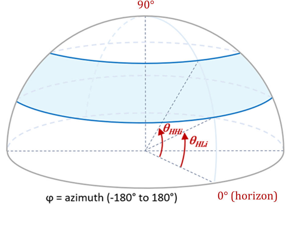
Figure 9.9.2.2-1: Definitions of θ HLi and θ HHi angles.
10 Radiated receiver characteristics
10.1 General
Radiated receiver characteristics are specified at RIB for BS type 1-H , BS type 1-O , or BS type 2-O , with full complement of transceivers for the configuration in normal operating condition.
Unless otherwise stated, the following arrangements apply for the radiated receiver characteristics requirements in clause 10:
-
Requirements apply during the BS receive period.
-
Requirements shall be met for any transmitter setting.
-
For FDD operation the requirements shall be met with the transmitter unit(s) ON.
-
Throughput requirements defined for the radiated receiver characteristics do not assume HARQ retransmissions.
-
When BS is configured to receive multiple carriers, all the throughput requirements are applicable for each received carrier.
-
For ACS, blocking and intermodulation characteristics, the negative offsets of the interfering signal apply relative to the lower Base Station RF Bandwidth edge or sub-block edge inside a sub-block gap , and the positive offsets of the interfering signal apply relative to the upper Base Station RF Bandwidth edge or sub-block edge inside a sub-block gap .
-
Each requirement shall be met over the RoAoA specified.
NOTE 1: In normal operating condition the BS in FDD operation is configured to transmit and receive at the same time.
NOTE 2: In normal operating condition the BS in TDD operation is configured to TX OFF power during receive period .
For FR1 requirements which are to be met over the OTA REFSENS RoAoA absolute requirement values are offset by the following term:
Δ OTAREFSENS = 44.1 - 10log 10 (BeW θ,REFSENS BeW φ,REFSENS ) dB for the reference direction
and
Δ OTAREFSENS = 41.1 - 10log 10 (BeW θ,REFSENS BeW φ,REFSENS ) dB for all other directions
For requirements which are to be met over the minSENS RoAoA absolute requirement values are offset by the following term:
Δ minSENS = P REFSENS – EIS minSENS (dB)
For FR2 requirements which are to be met over the OTA REFSENS RoAoA absolute requirement values are offset by the following term:
Δ FR2_REFSENS = -3 dB for the reference direction
and
Δ FR2_REFSENS = 0 dB for all other directions
Unless stated otherwise, the requirements for BS type 1-H and BS type 1-O are applied for ATG BS type 1-H and 1-O , respectively.
10.2 OTA sensitivity
10.2.1 BS type 1-H and BS type 1-O
10.2.1.1 General
The OTA sensitivity requirement is a directional requirement based upon the declaration of one or more OTA sensitivity direction declarations (OSDD), related to a BS type 1-H and BS type 1-O receiver.
The BS type 1-H and BS type 1-O may optionally be capable of redirecting/changing the receiver target by means of adjusting BS settings resulting in multiple sensitivity RoAoA . The sensitivity RoAoA resulting from the current BS settings is the active sensitivity RoAoA .
If the BS is capable of redirecting the receiver target related to the OSDD then the OSDD shall include:
-
BS channel bandwidth and declared minimum EIS level applicable to any active sensitivity RoAoA inside the receiver target redirection range in the OSDD.
-
A declared receiver target redirection range , describing all the angles of arrival that can be addressed for the OSDD through alternative settings in the BS.
-
Five declared sensitivity RoAoA comprising the conformance testing directions as detailed in TS 38.141-2 [6].
-
The receiver target reference direction .
NOTE 1: Some of the declared sensitivity RoAoA may coincide depending on the redirection capability.
NOTE 2: In addition to the declared sensitivity RoAoA , several sensitivity RoAoA may be implicitly defined by the receiver target redirection range without being explicitly declared in the OSDD.
NOTE 3: (Void)
If the BS is not capable of redirecting the receiver target related to the OSDD, then the OSDD includes only:
-
The set(s) of RAT, BS channel bandwidth and declared minimum EIS level applicable to the sensitivity RoAoA in the OSDD.
-
One declared active sensitivity RoAoA .
-
The receiver target reference direction .
NOTE 4: For BS without target redirection capability, the declared (fixed) sensitivity RoAoA is always the active sensitivity RoAoA .
The OTA sensitivity EIS level declaration shall apply to each supported polarization, under the assumption of polarization match .
10.2.1.2 Minimum requirement
For a received signal whose AoA of the incident wave is within the active sensitivity RoAoA of an OSDD, the error rate criterion as described in clause 7.2 shall be met when the level of the arriving signal is equal to the minimum EIS level in the respective declared set of EIS level and BS channel bandwidth .
10.2.2 BS type 2-O
There is no OTA sensitivity requirement for FR2, the OTA sensitivity is the same as the OTA reference sensitivity in clause 10.3.
10.3 OTA reference sensitivity level
10.3.1 General
The OTA REFSENS requirement is a directional requirement and is intended to ensure the minimum OTA reference sensitivity level for a declared OTA REFSENS RoAoA . The OTA reference sensitivity power level EIS REFSENS is the minimum mean power received at the RIB at which a reference performance requirement shall be met for a specified reference measurement channel.
The OTA REFSENS requirement shall apply to each supported polarization, under the assumption of polarization match .
10.3.2 Minimum requirement for BS type 1-O
The throughput shall be ≥ 95% of the maximum throughput of the reference measurement channel as specified in the corresponding table and annex A.1 when the OTA test signal is at the corresponding EIS REFSENS level and arrives from any direction within the OTA REFSENS RoAoA.
Table 10.3.2-1: Wide Area BS reference sensitivity levels
| BS channel bandwidth (MHz) | Sub-carrier spacing (kHz) | Reference measurement channel | OTA reference sensitivity level, EIS REFSENS (dBm) |
|---|---|---|---|
| 5, 7, 10, 15 | 15 | G-FR1-A1-1 | -101.7 - Δ OTAREFSENS |
| 10, 15 | 30 | G-FR1-A1-2 | -101.8 - Δ OTAREFSENS |
| 10, 15 | 60 | G-FR1-A1-3 | -98.9 - Δ OTAREFSENS |
| 20, 25, 30, 35, 40, 45, 50 | 15 | G-FR1-A1-4 | -95.3 - Δ OTAREFSENS |
| 20, 25, 30, 35, 40, 45, 50, 60, 70, 80, 90, 100 | 30 | G-FR1-A1-5 | -95.6 - Δ OTAREFSENS |
| 20, 25, 30, 35, 40, 45, 50, 60, 70, 80, 90, 100 | 60 | G-FR1-A1-6 | -95.7 - Δ OTAREFSENS |
| NOTE: EIS REFSENS is the power level of a single instance of the reference measurement channel. This requirement shall be met for each consecutive application of a single instance of the reference measurement channel mapped to disjoint frequency ranges with a width corresponding to the number of resource blocks of the reference measurement channel each, except for one instance that might overlap one other instance to cover the full BS channel bandwidth . |
Table 10.3.2-1a: Wide Area BS reference sensitivity levels for n104
| BS channel bandwidth (MHz) | Sub-carrier spacing (kHz) | Reference measurement channel | OTA reference sensitivity level, EIS REFSENS (dBm) |
|---|---|---|---|
| 20, 30, 40, 50 | 15 | G-FR1-A1-4 | -94.3 - Δ OTAREFSENS |
| 20, 30, 40, 50, 60, 70, 80, 90, 100 | 30 | G-FR1-A1-5 | -94.6 - Δ OTAREFSENS |
| 20, 30, 40, 50, 60, 70, 80, 90, 100 | 60 | G-FR1-A1-6 | -94.7 - Δ OTAREFSENS |
| NOTE: EIS REFSENS is the power level of a single instance of the reference measurement channel. This requirement shall be met for each consecutive application of a single instance of the reference measurement channel mapped to disjoint frequency ranges with a width corresponding to the number of resource blocks of the reference measurement channel each, except for one instance that might overlap one other instance to cover the full BS channel bandwidth . |
Table 10.3.2-2: Medium Range BS reference sensitivity levels
| BS channel bandwidth (MHz) | Sub-carrier spacing (kHz) | Reference measurement channel | OTA reference sensitivity level, EIS REFSENS (dBm) |
|---|---|---|---|
| 5, 7, 10, 15 | 15 | G-FR1-A1-1 | -96.7 - Δ OTAREFSENS |
| 10, 15 | 30 | G-FR1-A1-2 | -96.8 - Δ OTAREFSENS |
| 10, 15 | 60 | G-FR1-A1-3 | -93.9 - Δ OTAREFSENS |
| 20, 25, 30, 35, 40, 45, 50 | 15 | G-FR1-A1-4 | -90.3 - Δ OTAREFSENS |
| 20, 25, 30, 35, 40, 45, 50, 60, 70, 80, 90, 100 | 30 | G-FR1-A1-5 | -90.6 - Δ OTAREFSENS |
| 20, 25, 30, 35, 40, 45, 50, 60, 70, 80, 90, 100 | 60 | G-FR1-A1-6 | -90.7 - Δ OTAREFSENS |
| NOTE: EIS REFSENS is the power level of a single instance of the reference measurement channel. This requirement shall be met for each consecutive application of a single instance of the reference measurement channel mapped to disjoint frequency ranges with a width corresponding to the number of resource blocks of the reference measurement channel each, except for one instance that might overlap one other instance to cover the full BS channel bandwidth . |
Table 10.3.2-2a: Medium Range BS reference sensitivity levels for n104
| BS channel bandwidth (MHz) | Sub-carrier spacing (kHz) | Reference measurement channel | OTA reference sensitivity level, EIS REFSENS (dBm) |
|---|---|---|---|
| 20, 30, 40, 50 | 15 | G-FR1-A1-4 | -89.3 - Δ OTAREFSENS |
| 20, 30, 40, 50, 60, 70, 80, 90, 100 | 30 | G-FR1-A1-5 | -89.6 - Δ OTAREFSENS |
| 20, 30, 40, 50, 60, 70, 80, 90, 100 | 60 | G-FR1-A1-6 | -89.7 - Δ OTAREFSENS |
| NOTE: EIS REFSENS is the power level of a single instance of the reference measurement channel. This requirement shall be met for each consecutive application of a single instance of the reference measurement channel mapped to disjoint frequency ranges with a width corresponding to the number of resource blocks of the reference measurement channel each, except for one instance that might overlap one other instance to cover the full BS channel bandwidth . |
Table 10.3.2-3: Local Area BS reference sensitivity levels
| BS channel bandwidth (MHz) | Sub-carrier spacing (kHz) | Reference measurement channel | OTA reference sensitivity level, EIS REFSENS (dBm) |
|---|---|---|---|
| 5, 7, 10, 15 | 15 | G-FR1-A1-1 | -93.7 - Δ OTAREFSENS |
| 10, 15 | 30 | G-FR1-A1-2 | -93.8 - Δ OTAREFSENS |
| 10, 15 | 60 | G-FR1-A1-3 | -90.9 - Δ OTAREFSENS |
| 20, 25, 30, 35, 40, 45, 50 | 15 | G-FR1-A1-4 | -87.3 - Δ OTAREFSENS |
| 20, 25, 30, 35, 40, 45, 50, 60, 70, 80, 90, 100 | 30 | G-FR1-A1-5 | -87.6 - Δ OTAREFSENS |
| 20, 25, 30, 35, 40, 45, 50, 60, 70, 80, 90, 100 | 60 | G-FR1-A1-6 | -87.7 - Δ OTAREFSENS |
| NOTE: EIS REFSENS is the power level of a single instance of the reference measurement channel. This requirement shall be met for each consecutive application of a single instance of the reference measurement channel mapped to disjoint frequency ranges with a width corresponding to the number of resource blocks of the reference measurement channel each, except for one instance that might overlap one other instance to cover the full BS channel bandwidth . |
Table 10.3.2-3a: Local Area BS reference sensitivity levels for n104
| BS channel bandwidth (MHz) | Sub-carrier spacing (kHz) | Reference measurement channel | OTA reference sensitivity level, EIS REFSENS (dBm) |
|---|---|---|---|
| 20, 30, 40, 50 | 15 | G-FR1-A1-4 | -86.3 - Δ OTAREFSENS |
| 20, 30, 40, 50, 60, 70, 80, 90, 100 | 30 | G-FR1-A1-5 | -86.6 - Δ OTAREFSENS |
| 20, 30, 40, 50, 60, 70, 80, 90, 100 | 60 | G-FR1-A1-6 | -86.7 - Δ OTAREFSENS |
| NOTE 1: EIS REFSENS is the power level of a single instance of the reference measurement channel. This requirement shall be met for each consecutive application of a single instance of the reference measurement channel mapped to disjoint frequency ranges with a width corresponding to the number of resource blocks of the reference measurement channel each, except for one instance that might overlap one other instance to cover the full BS channel bandwidth . |
10.3.3 Minimum requirement for BS type 2-O
The throughput shall be ≥ 95% of the maximum throughput of the reference measurement channel as specified in the corresponding table and annex A.1 when the OTA test signal is at the corresponding EIS REFSENS level and arrives from any direction within the OTA REFSENS RoAoA .
EIS REFSENS levels are derived from a single declared basis level EIS REFSENS_50M, which is based on a reference measurement channel with 50 MHz BS channel bandwidth . EIS REFSENS_50M itself is not a requirement and although it is based on a reference measurement channel with 50 MHz BS channel bandwidth it does not imply that BS has to support 50 MHz BS channel bandwidth .
For Wide Area BS, EIS REFSENS_50M is an integer value in the range -96 to -119 dBm. The specific value is declared by the vendor.
For Medium Range BS, EIS REFSENS_50M is an integer value in the range -91 to -114 dBm. The specific value is declared by the vendor.
For Local Area BS, EIS REFSENS_50M is an integer value in the range -86 to -109 dBm. The specific value is declared by the vendor.
Table 10.3.3-1: FR2 OTA reference sensitivity requirement
| Frequency Range | BS channel Bandwidth (MHz) | Sub-carrier spacing (kHz) | Reference measurement channel | OTA reference sensitivity level, EIS REFSENS (dBm) |
|---|---|---|---|---|
| FR2-1 | 50, 100, 200 | 60 | G-FR2-A1-1 | EIS REFSENS_50M + Δ FR2_REFSENS |
| 50 | 120 | G-FR2-A1-2 | EIS REFSENS_50M + Δ FR2_REFSENS | |
| 100, 200, 400 | 120 | G-FR2-A1-3 | EIS REFSENS_50M + 3 + Δ FR2_REFSENS | |
| FR2-2 | 100,400 | 120 | G-FR2-A1-3 | EIS REFSENS_50M + 3 + Δ FR2_REFSENS |
| 400, 800, 1600 | 480 | G-FR2-A1-6 | EIS REFSENS_50M + 9 + Δ FR2_REFSENS | |
| 400, 800, 1600, 2000 | 960 | G-FR2-A1-7 | EIS REFSENS_50M + 9 + Δ FR2_REFSENS | |
| NOTE 1: EIS REFSENS is the power level of a single instance of the reference measurement channel. This requirement shall be met for each consecutive application of a single instance of the reference measurement channel mapped to disjoint frequency ranges with a width corresponding to the number of resource blocks of the reference measurement channel each, except for one instance that might overlap one other instance to cover the full BS channel bandwidth . NOTE 2: The declared EIS REFSENS_50M shall be within the range specified above. |
10.4 OTA dynamic range
10.4.1 General
The OTA dynamic range is a measure of the capability of the receiver unit to receive a wanted signal in the presence of an interfering signal inside the received BS channel bandwidth .
The requirement shall apply at the RIB when the AoA of the incident wave of a received signal and the interfering signal are from the same direction and are within the OTA REFSENS RoAoA.
The wanted and interfering signals apply to each supported polarization, under the assumption of polarization match .
10.4.2 Minimum requirement for BS type 1-O
For NR, the throughput shall be ≥ 95% of the maximum throughput of the reference measurement channel.
Table 10.4.2-1: Wide Area BS OTA dynamic range for NR carrier
| BS channel bandwidth (MHz) | Subcarrier spacing (kHz) | Reference measurement channel | Wanted signal mean power (dBm) | Interfering signal mean power (dBm) / BW Config | Type of interfering signal |
|---|---|---|---|---|---|
| 5 | 15 | G-FR1-A2-1 | -70.7- Δ OTAREFSENS | -82.5- Δ OTAREFSENS | AWGN |
| 30 | G-FR1-A2-2 | -71.4- Δ OTAREFSENS | |||
| 7 | 15 | G-FR1-A2-1 | -70.7- Δ OTAREFSENS | -81.0- Δ OTAREFSENS | AWGN |
| 10 | 15 | G-FR1-A2-1 | -70.7- Δ OTAREFSENS | -79.3- Δ OTAREFSENS | AWGN |
| 30 | G-FR1-A2-2 | -71.4- Δ OTAREFSENS | |||
| 60 | G-FR1-A2-3 | -68.4- Δ OTAREFSENS | |||
| 15 | 15 | G-FR1-A2-1 | -70.7- Δ OTAREFSENS | -77.5- Δ OTAREFSENS | AWGN |
| 30 | G-FR1-A2-2 | -71.4- Δ OTAREFSENS | |||
| 60 | G-FR1-A2-3 | -68.4- Δ OTAREFSENS | |||
| 20 | 15 | G-FR1-A2-4 | -64.5- Δ OTAREFSENS | -76.2- Δ OTAREFSENS | AWGN |
| 30 | G-FR1-A2-5 | -64.5- Δ OTAREFSENS | |||
| 60 | G-FR1-A2-6 | -64.8- Δ OTAREFSENS | |||
| 25 | 15 | G-FR1-A2-4 | -64.5- Δ OTAREFSENS | -75.2- Δ OTAREFSENS | AWGN |
| 30 | G-FR1-A2-5 | -64.5- Δ OTAREFSENS | |||
| 60 | G-FR1-A2-6 | -64.8- Δ OTAREFSENS | |||
| 30 | 15 | G-FR1-A2-4 | -64.5- Δ OTAREFSENS | -74.4- Δ OTAREFSENS | AWGN |
| 30 | G-FR1-A2-5 | -64.5- Δ OTAREFSENS | |||
| 60 | G-FR1-A2-6 | -64.8- Δ OTAREFSENS | |||
| 35 | 15 | G-FR1-A2-4 | -64.5- Δ OTAREFSENS | -73.7- Δ OTAREFSENS | AWGN |
| 30 | G-FR1-A2-5 | -64.5- Δ OTAREFSENS | |||
| 60 | G-FR1-A2-6 | -64.8- Δ OTAREFSENS | |||
| 40 | 15 | G-FR1-A2-4 | -64.5- Δ OTAREFSENS | -73.1- Δ OTAREFSENS | AWGN |
| 30 | G-FR1-A2-5 | -64.5- Δ OTAREFSENS | |||
| 60 | G-FR1-A2-6 | -64.8- Δ OTAREFSENS | |||
| 45 | 15 | G-FR1-A2-4 | -64.5- Δ OTAREFSENS | -72.6- Δ OTAREFSENS | AWGN |
| 30 | G-FR1-A2-5 | -64.5- Δ OTAREFSENS | |||
| 60 | G-FR1-A2-6 | -64.8- Δ OTAREFSENS | |||
| 50 | 15 | G-FR1-A2-4 | -64.5- Δ OTAREFSENS | -72.1- Δ OTAREFSENS | AWGN |
| 30 | G-FR1-A2-5 | -64.5- Δ OTAREFSENS | |||
| 60 | G-FR1-A2-6 | -64.8- Δ OTAREFSENS | |||
| 60 | 30 | G-FR1-A2-5 | -64.5- Δ OTAREFSENS | -71.3- Δ OTAREFSENS | AWGN |
| 60 | G-FR1-A2-6 | -64.8- Δ OTAREFSENS | |||
| 70 | 30 | G-FR1-A2-5 | -64.5- Δ OTAREFSENS | -70.7- Δ OTAREFSENS | AWGN |
| 60 | G-FR1-A2-6 | -64.8- Δ OTAREFSENS | |||
| 80 | 30 | G-FR1-A2-5 | -64.5- Δ OTAREFSENS | -70.1- Δ OTAREFSENS | AWGN |
| 60 | G-FR1-A2-6 | -64.8- Δ OTAREFSENS | |||
| 90 | 30 | G-FR1-A2-5 | -64.5- Δ OTAREFSENS | -69.5- Δ OTAREFSENS | AWGN |
| 60 | G-FR1-A2-6 | -64.8- Δ OTAREFSENS | |||
| 100 | 30 | G-FR1-A2-5 | -64.5- Δ OTAREFSENS | -69.1- Δ OTAREFSENS | AWGN |
| 60 | G-FR1-A2-6 | -64.8- Δ OTAREFSENS | |||
| NOTE: The wanted signal mean power is the power level of a single instance of the corresponding reference measurement channel. This requirement shall be met for each consecutive application of a single instance of the reference measurement channel mapped to disjoint frequency ranges with a width corresponding to the number of resource blocks of the reference measurement channel each, except for one instance that might overlap one other instance to cover the full BS channel bandwidth . |
Table 10.4.2-1a: Wide Area BS OTA dynamic range for NR carrier of band n104
| BS channel bandwidth (MHz) | Subcarrier spacing (kHz) | Reference measurement channel | Wanted signal mean power (dBm) | Interfering signal mean power (dBm) / BW Config | Type of interfering signal |
|---|---|---|---|---|---|
| 20 | 15 | G-FR1-A2-4 | -63.5- Δ OTAREFSENS | -75.2- Δ OTAREFSENS | AWGN |
| 30 | G-FR1-A2-5 | -63.5- Δ OTAREFSENS | |||
| 60 | G-FR1-A2-6 | -63.8- Δ OTAREFSENS | |||
| 30 | 15 | G-FR1-A2-4 | -63.5- Δ OTAREFSENS | -73.4- Δ OTAREFSENS | AWGN |
| 30 | G-FR1-A2-5 | -63.5- Δ OTAREFSENS | |||
| 60 | G-FR1-A2-6 | -63.8- Δ OTAREFSENS | |||
| 40 | 15 | G-FR1-A2-4 | -63.5- Δ OTAREFSENS | -72.1- Δ OTAREFSENS | AWGN |
| 30 | G-FR1-A2-5 | -63.5- Δ OTAREFSENS | |||
| 60 | G-FR1-A2-6 | -63.8- Δ OTAREFSENS | |||
| 50 | 15 | G-FR1-A2-4 | -63.5- Δ OTAREFSENS | -71.1- Δ OTAREFSENS | AWGN |
| 30 | G-FR1-A2-5 | -63.5- Δ OTAREFSENS | |||
| 60 | G-FR1-A2-6 | -63.8- Δ OTAREFSENS | |||
| 60 | 30 | G-FR1-A2-5 | -63.5- Δ OTAREFSENS | -70.3- Δ OTAREFSENS | AWGN |
| 60 | G-FR1-A2-6 | -63.8- Δ OTAREFSENS | |||
| 70 | 30 | G-FR1-A2-5 | -63.5- Δ OTAREFSENS | -69.7- Δ OTAREFSENS | AWGN |
| 60 | G-FR1-A2-6 | -63.8- Δ OTAREFSENS | |||
| 80 | 30 | G-FR1-A2-5 | -63.5- Δ OTAREFSENS | -69.1- Δ OTAREFSENS | AWGN |
| 60 | G-FR1-A2-6 | -63.8- Δ OTAREFSENS | |||
| 90 | 30 | G-FR1-A2-5 | -63.5- Δ OTAREFSENS | -68.5- Δ OTAREFSENS | AWGN |
| 60 | G-FR1-A2-6 | -63.8- Δ OTAREFSENS | |||
| 100 | 30 | G-FR1-A2-5 | -63.5- Δ OTAREFSENS | -68.1- Δ OTAREFSENS | AWGN |
| 60 | G-FR1-A2-6 | -63.8- Δ OTAREFSENS | |||
| NOTE 1: The wanted signal mean power is the power level of a single instance of the corresponding reference measurement channel. This requirement shall be met for each consecutive application of a single instance of the reference measurement channel mapped to disjoint frequency ranges with a width corresponding to the number of resource blocks of the reference measurement channel each, except for one instance that might overlap one other instance to cover the full BS channel bandwidth . |
Table 10.4.2-2: Medium Range BS OTA dynamic range for NR carrier
| BS channel bandwidth (MHz) | Subcarrier spacing (kHz) | Reference measurement channel | Wanted signal mean power (dBm) | Interfering signal mean power (dBm) / BW Config | Type of interfering signal |
|---|---|---|---|---|---|
| 5 | 15 | G-FR1-A2-1 | -65.7- Δ OTAREFSENS | -77.5- Δ OTAREFSENS | AWGN |
| 30 | G-FR1-A2-2 | -66.4- Δ OTAREFSENS | |||
| 7 | 15 | G-FR1-A2-1 | -65.7- Δ OTAREFSENS | -76.0- Δ OTAREFSENS | AWGN |
| 10 | 15 | G-FR1-A2-1 | -65.7- Δ OTAREFSENS | -74.3- Δ OTAREFSENS | AWGN |
| 30 | G-FR1-A2-2 | -66.4- Δ OTAREFSENS | |||
| 60 | G-FR1-A2-3 | -63.4- Δ OTAREFSENS | |||
| 15 | 15 | G-FR1-A2-1 | -65.7- Δ OTAREFSENS | -72.5- Δ OTAREFSENS | AWGN |
| 30 | G-FR1-A2-2 | -66.4- Δ OTAREFSENS | |||
| 60 | G-FR1-A2-3 | -63.4- Δ OTAREFSENS | |||
| 20 | 15 | G-FR1-A2-4 | -59.5- Δ OTAREFSENS | -71.2- Δ OTAREFSENS | AWGN |
| 30 | G-FR1-A2-5 | -59.5- Δ OTAREFSENS | |||
| 60 | G-FR1-A2-6 | -59.8- Δ OTAREFSENS | |||
| 25 | 15 | G-FR1-A2-4 | -59.5- Δ OTAREFSENS | -70.2- Δ OTAREFSENS | AWGN |
| 30 | G-FR1-A2-5 | -59.5- Δ OTAREFSENS | |||
| 60 | G-FR1-A2-6 | -59.8- Δ OTAREFSENS | |||
| 30 | 15 | G-FR1-A2-4 | -59.5- Δ OTAREFSENS | -69.4- Δ OTAREFSENS | AWGN |
| 30 | G-FR1-A2-5 | -59.5- Δ OTAREFSENS | |||
| 60 | G-FR1-A2-6 | -59.8- Δ OTAREFSENS | |||
| 35 | 15 | G-FR1-A2-4 | -59.5- Δ OTAREFSENS | -68.7- Δ OTAREFSENS | AWGN |
| 30 | G-FR1-A2-5 | -59.5- Δ OTAREFSENS | |||
| 60 | G-FR1-A2-6 | -59.8- Δ OTAREFSENS | |||
| 40 | 15 | G-FR1-A2-4 | -59.5- Δ OTAREFSENS | -68.1- Δ OTAREFSENS | AWGN |
| 30 | G-FR1-A2-5 | -59.5- Δ OTAREFSENS | |||
| 60 | G-FR1-A2-6 | -59.8- Δ OTAREFSENS | |||
| 45 | 15 | G-FR1-A2-4 | -59.5- Δ OTAREFSENS | -67.6- Δ OTAREFSENS | AWGN |
| 30 | G-FR1-A2-5 | -59.5- Δ OTAREFSENS | |||
| 60 | G-FR1-A2-6 | -59.8- Δ OTAREFSENS | |||
| 50 | 15 | G-FR1-A2-4 | -59.5- Δ OTAREFSENS | -67.1- Δ OTAREFSENS | AWGN |
| 30 | G-FR1-A2-5 | -59.5- Δ OTAREFSENS | |||
| 60 | G-FR1-A2-6 | -59.8- Δ OTAREFSENS | |||
| 60 | 30 | G-FR1-A2-5 | -59.5- Δ OTAREFSENS | -66.3- Δ OTAREFSENS | AWGN |
| 60 | G-FR1-A2-6 | -59.8- Δ OTAREFSENS | |||
| 70 | 30 | G-FR1-A2-5 | -59.5- Δ OTAREFSENS | -65.7- Δ OTAREFSENS | AWGN |
| 60 | G-FR1-A2-6 | -59.8- Δ OTAREFSENS | |||
| 80 | 30 | G-FR1-A2-5 | -59.5- Δ OTAREFSENS | -65.1- Δ OTAREFSENS | AWGN |
| 60 | G-FR1-A2-6 | -59.8- Δ OTAREFSENS | |||
| 90 | 30 | G-FR1-A2-5 | -59.5- Δ OTAREFSENS | -64.5- Δ OTAREFSENS | AWGN |
| 60 | G-FR1-A2-6 | -59.8- Δ OTAREFSENS | |||
| 100 | 30 | G-FR1-A2-5 | -59.5- Δ OTAREFSENS | -64.1- Δ OTAREFSENS | AWGN |
| 60 | G-FR1-A2-6 | -59.8- Δ OTAREFSENS | |||
| NOTE: The wanted signal mean power is the power level of a single instance of the corresponding reference measurement channel. This requirement shall be met for each consecutive application of a single instance of the reference measurement channel mapped to disjoint frequency ranges with a width corresponding to the number of resource blocks of the reference measurement channel each, except for one instance that might overlap one other instance to cover the full BS channel bandwidth . |
Table 10.4.2-2a: Medium Range BS OTA dynamic range for NR carrier of band n104
| BS channel bandwidth (MHz) | Subcarrier spacing (kHz) | Reference measurement channel (Note 2) | Wanted signal mean power (dBm) | Interfering signal mean power (dBm) / BW Config | Type of interfering signal |
|---|---|---|---|---|---|
| 20 | 15 | G-FR1-A2-4 | -58.5- Δ OTAREFSENS | -70.2- Δ OTAREFSENS | AWGN |
| 30 | G-FR1-A2-5 | -58.5- Δ OTAREFSENS | |||
| 60 | G-FR1-A2-6 | -58.8- Δ OTAREFSENS | |||
| 30 | 15 | G-FR1-A2-4 | -58.5- Δ OTAREFSENS | -68.4- Δ OTAREFSENS | AWGN |
| 30 | G-FR1-A2-5 | -58.5- Δ OTAREFSENS | |||
| 60 | G-FR1-A2-6 | -58.8- Δ OTAREFSENS | |||
| 40 | 15 | G-FR1-A2-4 | -58.5- Δ OTAREFSENS | -67.1- Δ OTAREFSENS | AWGN |
| 30 | G-FR1-A2-5 | -58.5- Δ OTAREFSENS | |||
| 60 | G-FR1-A2-6 | -58.8- Δ OTAREFSENS | |||
| 50 | 15 | G-FR1-A2-4 | -58.5- Δ OTAREFSENS | -66.1- Δ OTAREFSENS | AWGN |
| 30 | G-FR1-A2-5 | -58.5- Δ OTAREFSENS | |||
| 60 | G-FR1-A2-6 | -58.8- Δ OTAREFSENS | |||
| 60 | 30 | G-FR1-A2-5 | -58.5- Δ OTAREFSENS | -65.3- Δ OTAREFSENS | AWGN |
| 60 | G-FR1-A2-6 | -58.8- Δ OTAREFSENS | |||
| 70 | 30 | G-FR1-A2-5 | -58.5- Δ OTAREFSENS | -64.7- Δ OTAREFSENS | AWGN |
| 60 | G-FR1-A2-6 | -58.8- Δ OTAREFSENS | |||
| 80 | 30 | G-FR1-A2-5 | -58.5- Δ OTAREFSENS | -64.1- Δ OTAREFSENS | AWGN |
| 60 | G-FR1-A2-6 | -58.8- Δ OTAREFSENS | |||
| 90 | 30 | G-FR1-A2-5 | -58.5- Δ OTAREFSENS | -63.5- Δ OTAREFSENS | AWGN |
| 60 | G-FR1-A2-6 | -58.8- Δ OTAREFSENS | |||
| 100 | 30 | G-FR1-A2-5 | -58.5- Δ OTAREFSENS | -63.1- Δ OTAREFSENS | AWGN |
| 60 | G-FR1-A2-6 | -58.8- Δ OTAREFSENS | |||
| NOTE 1: The wanted signal mean power is the power level of a single instance of the corresponding reference measurement channel. This requirement shall be met for each consecutive application of a single instance of the reference measurement channel mapped to disjoint frequency ranges with a width corresponding to the number of resource blocks of the reference measurement channel each, except for one instance that might overlap one other instance to cover the full BS channel bandwidth . |
Table 10.4.2-3: Local Area BS OTA dynamic range for NR carrier
| BS channel bandwidth (MHz) | Subcarrier spacing (kHz) | Reference measurement channel | Wanted signal mean power (dBm) | Interfering signal mean power (dBm) / BW Config | Type of interfering signal |
|---|---|---|---|---|---|
| 5 | 15 | G-FR1-A2-1 | -62.7- Δ OTAREFSENS | -74.5- Δ OTAREFSENS | AWGN |
| 30 | G-FR1-A2-2 | -64.4- Δ OTAREFSENS | |||
| 7 | 15 | G-FR1-A2-1 | -62.7- Δ OTAREFSENS | -73.0- Δ OTAREFSENS | AWGN |
| 10 | 15 | G-FR1-A2-1 | -62.7- Δ OTAREFSENS | -71.3- Δ OTAREFSENS | AWGN |
| 30 | G-FR1-A2-2 | -64.4- Δ OTAREFSENS | |||
| 60 | G-FR1-A2-3 | -60.4- Δ OTAREFSENS | |||
| 15 | 15 | G-FR1-A2-1 | -62.7- Δ OTAREFSENS | -69.5- Δ OTAREFSENS | AWGN |
| 30 | G-FR1-A2-2 | -64.4- Δ OTAREFSENS | |||
| 60 | G-FR1-A2-3 | -60.4- Δ OTAREFSENS | |||
| 20 | 15 | G-FR1-A2-4 | -56.5- Δ OTAREFSENS | -68.2- Δ OTAREFSENS | AWGN |
| 30 | G-FR1-A2-5 | -56.5- Δ OTAREFSENS | |||
| 60 | G-FR1-A2-6 | -56.8- Δ OTAREFSENS | |||
| 25 | 15 | G-FR1-A2-4 | -56.5- Δ OTAREFSENS | -67.2- Δ OTAREFSENS | AWGN |
| 30 | G-FR1-A2-5 | -56.5- Δ OTAREFSENS | |||
| 60 | G-FR1-A2-6 | -56.8- Δ OTAREFSENS | |||
| 30 | 15 | G-FR1-A2-4 | -56.5- Δ OTAREFSENS | -66.4- Δ OTAREFSENS | AWGN |
| 30 | G-FR1-A2-5 | -56.5- Δ OTAREFSENS | |||
| 60 | G-FR1-A2-6 | -56.8- Δ OTAREFSENS | |||
| 35 | 15 | G-FR1-A2-4 | -56.5- Δ OTAREFSENS | -65.7- Δ OTAREFSENS | AWGN |
| 30 | G-FR1-A2-5 | -56.5- Δ OTAREFSENS | |||
| 60 | G-FR1-A2-6 | -56.8- Δ OTAREFSENS | |||
| 40 | 15 | G-FR1-A2-4 | -56.5- Δ OTAREFSENS | -65.1- Δ OTAREFSENS | AWGN |
| 30 | G-FR1-A2-5 | -56.5- Δ OTAREFSENS | |||
| 60 | G-FR1-A2-6 | -56.8- Δ OTAREFSENS | |||
| 45 | 15 | G-FR1-A2-4 | -56.5- Δ OTAREFSENS | -64.6- Δ OTAREFSENS | AWGN |
| 30 | G-FR1-A2-5 | -56.5- Δ OTAREFSENS | |||
| 60 | G-FR1-A2-6 | -56.8- Δ OTAREFSENS | |||
| 50 | 15 | G-FR1-A2-4 | -56.5- Δ OTAREFSENS | -64.1- Δ OTAREFSENS | AWGN |
| 30 | G-FR1-A2-5 | -56.5- Δ OTAREFSENS | |||
| 60 | G-FR1-A2-6 | -56.8- Δ OTAREFSENS | |||
| 60 | 30 | G-FR1-A2-5 | -56.5- Δ OTAREFSENS | -63.3- Δ OTAREFSENS | AWGN |
| 60 | G-FR1-A2-6 | -56.8- Δ OTAREFSENS | |||
| 70 | 30 | G-FR1-A2-5 | -56.5- Δ OTAREFSENS | -62.7- Δ OTAREFSENS | AWGN |
| 60 | G-FR1-A2-6 | -56.8- Δ OTAREFSENS | |||
| 80 | 30 | G-FR1-A2-5 | -56.5- Δ OTAREFSENS | -62.1- Δ OTAREFSENS | AWGN |
| 60 | G-FR1-A2-6 | -56.8- Δ OTAREFSENS | |||
| 90 | 30 | G-FR1-A2-5 | -56.5- Δ OTAREFSENS | -61.5- Δ OTAREFSENS | AWGN |
| 60 | G-FR1-A2-6 | -56.8- Δ OTAREFSENS | |||
| 100 | 30 | G-FR1-A2-5 | -56.5- Δ OTAREFSENS | -61.1- Δ OTAREFSENS | AWGN |
| 60 | G-FR1-A2-6 | -56.8- Δ OTAREFSENS | |||
| NOTE: The wanted signal mean power is the power level of a single instance of the corresponding reference measurement channel. This requirement shall be met for each consecutive application of a single instance of the reference measurement channel mapped to disjoint frequency ranges with a width corresponding to the number of resource blocks of the reference measurement channel each, except for one instance that might overlap one other instance to cover the full BS channel bandwidth . |
Table 10.4.2-3a: Local Area BS OTA dynamic range for NR carrier of band n104
| BS channel bandwidth (MHz) | Subcarrier spacing (kHz) | Reference measurement channel | Wanted signal mean power (dBm) | Interfering signal mean power (dBm) / BW Config | Type of interfering signal |
|---|---|---|---|---|---|
| 20 | 15 | G-FR1-A2-4 | -55.5- Δ OTAREFSENS | -67.2- Δ OTAREFSENS | AWGN |
| 30 | G-FR1-A2-5 | -55.5- Δ OTAREFSENS | |||
| 60 | G-FR1-A2-6 | -55.8- Δ OTAREFSENS | |||
| 30 | 15 | G-FR1-A2-4 | -55.5- Δ OTAREFSENS | -65.4- Δ OTAREFSENS | AWGN |
| 30 | G-FR1-A2-5 | -55.5- Δ OTAREFSENS | |||
| 60 | G-FR1-A2-6 | -55.8- Δ OTAREFSENS | |||
| 40 | 15 | G-FR1-A2-4 | -55.5- Δ OTAREFSENS | -64.1- Δ OTAREFSENS | AWGN |
| 30 | G-FR1-A2-5 | -55.5- Δ OTAREFSENS | |||
| 60 | G-FR1-A2-6 | -55.8- Δ OTAREFSENS | |||
| 50 | 15 | G-FR1-A2-4 | -55.5- Δ OTAREFSENS | -63.1- Δ OTAREFSENS | AWGN |
| 30 | G-FR1-A2-5 | -55.5- Δ OTAREFSENS | |||
| 60 | G-FR1-A2-6 | -55.8- Δ OTAREFSENS | |||
| 60 | 30 | G-FR1-A2-5 | -55.5- Δ OTAREFSENS | -62.3- Δ OTAREFSENS | AWGN |
| 60 | G-FR1-A2-6 | -55.8- Δ OTAREFSENS | |||
| 70 | 30 | G-FR1-A2-5 | -55.5- Δ OTAREFSENS | -61.7- Δ OTAREFSENS | AWGN |
| 60 | G-FR1-A2-6 | -55.8- Δ OTAREFSENS | |||
| 80 | 30 | G-FR1-A2-5 | -55.5- Δ OTAREFSENS | -61.1- Δ OTAREFSENS | AWGN |
| 60 | G-FR1-A2-6 | -55.8- Δ OTAREFSENS | |||
| 90 | 30 | G-FR1-A2-5 | -55.5- Δ OTAREFSENS | -60.5- Δ OTAREFSENS | AWGN |
| 60 | G-FR1-A2-6 | -55.8- Δ OTAREFSENS | |||
| 100 | 30 | G-FR1-A2-5 | -55.5- Δ OTAREFSENS | -60.1- Δ OTAREFSENS | AWGN |
| 60 | G-FR1-A2-6 | -55.8- Δ OTAREFSENS | |||
| NOTE 1: The wanted signal mean power is the power level of a single instance of the corresponding reference measurement channel. This requirement shall be met for each consecutive application of a single instance of the reference measurement channel mapped to disjoint frequency ranges with a width corresponding to the number of resource blocks of the reference measurement channel each, except for one instance that might overlap one other instance to cover the full BS channel bandwidth . |
10.5 OTA in-band selectivity and blocking
10.5.1 OTA adjacent channel selectivity
10.5.1.1 General
OTA Adjacent channel selectivity (ACS) is a measure of the receiver’s ability to receive an OTA wanted signal at its assigned channel frequency in the presence of an OTA adjacent channel signal with a specified centre frequency offset of the interfering signal to the band edge of a victim system.
10.5.1.2 Minimum requirement for BS type 1-O
The requirement shall apply at the RIB when the AoA of the incident wave of a received signal and the interfering signal are from the same direction and are within the minSENS RoAoA .
The wanted and interfering signals apply to each supported polarization, under the assumption o f polarization match .
The throughput shall be ≥ 95% of the maximum throughput of the reference measurement channel.
For FR1 except for band n104 , the OTA wanted and the interfering signal are specified in table 10.5.1.2-1 and table 10.5.1.2-2 for OTA ACS. For band n104 , the OTA wanted and the interfering signal are specified in table 10.5.1.2-1a and table 10.5.1.2-2 for OTA ACS. The reference measurement channel for the OTA wanted signal is further specified in annex A.1. The characteristics of the interfering signal is further specified in annex D.
The OTA ACS requirement is applicable outside the Base Station RF Bandwidth or Radio Bandwidth . The OTA interfering signal offset is defined relative to the Base station RF Bandwidth edges or Radio Bandwidth edges .
For RIBs supporting operation in non-contiguous spectrum within any operating band , the OTA ACS requirement shall apply in addition inside any sub-block gap , in case the sub-block gap size is at least as wide as the NR interfering signal in table 10.5.1.2-2. The OTA interfering signal offset is defined relative to the sub-block edges inside the sub-block gap .
For multi-band RIBs , the OTA ACS requirement shall apply in addition inside any Inter RF Bandwidth gap , in case the Inter RF Bandwidth gap size is at least as wide as the NR interfering signal in table 10.5.1.2-2. The interfering signal offset is defined relative to the Base Station RF Bandwidth edges inside the Inter RF Bandwidth gap .
Table 10.5.1.2-1: OTA ACS requirement for BS type 1-O
| BS channel bandwidth of the lowest/highest carrier received (MHz) | Wanted signal mean power (dBm) (Note 2) | Interfering signal mean power (dBm) |
|---|---|---|
| 5, 7, 10, 15, 20, 25, 30, 35, 40, 45, 50, 60, 70, 80,90, 100 (Note 1) | EIS minSENS + 6 dB | Wide Area BS: -52 – Δ minSENS Medium Range BS: -47– Δ minSENS Local Area BS: -44– Δ minSENS |
| NOTE 1: The SCS for the lowest/highest carrier received is the lowest SCS supported by the BS for that bandwidth NOTE 2: EIS minSENS depends on the BS channel bandwidth |
Table 10.5.1.2-1a: OTA ACS requirement for BS type 1-O for band n104
| BS channel bandwidth of the lowest/highest carrier received (MHz) | Wanted signal mean power (dBm) (Note 2) | Interfering signal mean power (dBm) |
|---|---|---|
| 20, 30, 40, 50, 60, 70, 80,90, 100 (Note 1) | EIS minSENS + 6 dB | Wide Area BS: -55 – Δ minSENS Medium Range BS: -50– Δ minSENS Local Area BS: -47– Δ minSENS |
| NOTE 1: The SCS for the lowest/highest carrier received is the lowest SCS supported by the BS for that bandwidth NOTE 2: EIS minSENS depends on the BS channel bandwidth |
Table 10.5.1.2-2: OTA ACS interferer frequency offset for BS type 1-O
| BS channel bandwidth of the lowest/highest carrier received (MHz) | Interfering signal centre frequency offset from the lower/upper Base Station RF Bandwidth edge or sub-block edge inside a sub-block gap (MHz) | Type of interfering signal |
|---|---|---|
| 5 | ±2.5025 | |
| 7 | ±2.5075 | |
| 10 | ±2.5075 | 5 MHz DFT-s-OFDM NR signal, |
| 15 | ±2.5125 | 15 kHz SCS, 25 RBs |
| 20 | ±2.5025 | |
| 25 | ±9.4675 | |
| 30 | ±9.4725 | |
| 35 | ±9.4625 | |
| 40 | ±9.4675 | |
| 45 | ±9.4725 | |
| 50 | ±9.4625 | 20 MHz DFT-s-OFDM NR signal, |
| 60 | ±9.4725 | 15 kHz SCS, 100 RBs |
| 70 | ±9.4675 | |
| 80 | ±9.4625 | |
| 90 | ±9.4725 | |
| 100 | ±9.4675 |
10.5.1.3 Minimum requirement for BS type 2-O
The requirement shall apply at the RIB when the AoA of the incident wave of a received signal and the interfering signal are from the same direction and are within the OTA REFSENS RoAoA.
The wanted and interfering signals apply to each supported polarization, under the assumption o f polarization match .
The throughput shall be ≥ 95% of the maximum throughput of the reference measurement channel.
For FR2, the OTA wanted and the interfering signal are specified in table 10.5.1.3-1 and table 10.5.1.3-2 for OTA ACS. The reference measurement channel for the OTA wanted signal is further specified in annex A.1. The characteristics of the interfering signal is further specified in annex D.
The OTA ACS requirement is applicable outside the Base Station RF Bandwidth . The OTA interfering signal offset is defined relative to the Base station RF Bandwidth edges .
For RIBs supporting operation in non-contiguous spectrum within any operating band , the OTA ACS requirement shall apply in addition inside any sub-block gap , in case the sub-block gap size is at least as wide as the NR interfering signal in table 10.5.1.3-2. The OTA interfering signal offset is defined relative to the sub-block edges inside the sub-block gap .
Table 10.5.1.3-1: OTA ACS requirement for BS type 2-O
| Frequency Range | BS channel bandwidth of the lowest/highest carrier received (MHz) | Wanted signal mean power (dBm) | Interfering signal mean power (dBm) |
|---|---|---|---|
| FR2-1 | 50, 100, 200, 400 | EIS REFSENS + 6 dB (Note 3) | EIS REFSENS_50M + 27.7 + Δ FR2_REFSENS (Note 1) EIS REFSENS_50M + 26.7 + Δ FR2_REFSENS (Note 2) |
| FR2-2 | 100, 400, 800, 1600, 2000 | EIS REFSENS + 6 dB (Note 3) | EIS REFSENS_50M + 28.7 + Δ FR2_REFSENS (Note 4) |
| NOTE 1: Applicable to bands defined within the frequency spectrum range of 24.25 – 33.4 GHz NOTE 2: Applicable to bands defined within the frequency spectrum range of 37 – 52.6 GHz NOTE 3: EIS REFSENS is given in clause 10.3.3 NOTE 4: Applicable to bands defined within the frequency spectrum range of 57 – 71 GHz |
Table 10.5.1.3-2: OTA ACS interferer frequency offset for BS type 2-O
| Frequency Range | BS channel bandwidth of the lowest/highest carrier received (MHz) | Interfering signal centre frequency offset from the lower/upper Base Station RF Bandwidth edge or sub-block edge inside a sub-block gap (MHz) | Type of interfering signal |
|---|---|---|---|
| FR2-1 | 50 | ±24.29 | |
| FR2-1 | 100 | ±24.31 | 50 MHz DFT-s-OFDM NR |
| FR2-1 | 200 | ±24.29 | signal,60 kHz SCS, 64 RBs |
| FR2-1 | 400 | ±24.31 | |
| FR2-2 | 100 | ±48.58 | |
| 400 | ±48.58 | 100 MHz DFT-s-OFDM NR | |
| 800 | ±48.62 | signal,120 kHz SCS, 64 RBs | |
| 1600 | ±48.58 | ||
| 2000 | ±48.62 |
10.5.2 OTA in-band blocking
10.5.2.1 General
The OTA in-band blocking characteristics is a measure of the receiver’s ability to receive a OTA wanted signal at its assigned channel in the presence of an unwanted OTA interferer, which is an NR signal for general blocking or an NR signal with one RB for narrowband blocking.
10.5.2.2 Minimum requirement for BS type 1-O
The requirement shall apply at the RIB when the AoA of the incident wave of a received signal and the interfering signal are from the same direction, and:
-
when the wanted signal is based on EIS REFSENS : the AoA of the incident wave of a received signal and the interfering signal are within the OTA REFSENS RoAoA.
-
when the wanted signal is based on EIS minSENS : the AoA of the incident wave of a received signal and the interfering signal are within the minSENS RoAoA .
The wanted and interfering signals apply to each supported polarization, under the assumption of polarization match .
The throughput shall be ≥ 95% of the maximum throughput of the reference measurement channel, with OTA wanted and OTA interfering signal specified in tables 10.5.2.2-1, table 10.5.2.2-2 and table 10.5.2.2-3 for general OTA and narrowband OTA blocking requirements. Narrowband blocking requirements are not applied for band n104. The reference measurement channel for the OTA wanted signal is identified in clause 10.3.2 and are further specified in annex A.1. The characteristics of the interfering signal is further specified in annex D.
The OTA in-band blocking requirements apply outside the Base Station RF Bandwidth or Radio Bandwidth . The interfering signal offset is defined relative to the Base Station RF Bandwidth edges or Radio Bandwidth edges.
For BS type 1-O the OTA in-band blocking requirement shall apply in the in-band blocking frequency range, which is from F UL,low - Δf OOB to F UL,high + Δf OOB , excluding the downlink frequency range of the FDD operating band. The Δf OOB for BS type 1-O is defined in table 10.5.2.2-0 except for band n104 and 10.5.2.2-0a for band n104.
Table 10.5.2.2-0: Δf OOB offset for NR operating bands in FR1
| BS type | Operating band characteristics | Δf OOB (MHz) |
|---|---|---|
| BS type 1-O | F UL,high – F UL,low < 100 MHz | 20 |
| 100 MHz ≤ F UL,high – F UL,low ≤ 900 MHz | 60 |
For band n104, Δf OOB for BS type 1-O is defined in table 10.5.2.2-0a.
Table 10.5.2.2-0a: Δf OOB offset for NR operating bands for band n104
| BS type | Operating band | Δf OOB (MHz) |
|---|---|---|
| BS type 1-O | n104 | 100 |
For RIBs supporting operation in non-contiguous spectrum within any operating band , the OTA in-band blocking requirements apply in addition inside any sub-block gap , in case the sub-block gap size is at least as wide as twice the interfering signal minimum offset in table 10.5.2.2-1. The interfering signal offset is defined relative to the sub-block edges inside the sub-block gap .
For multi-band RIBs , the OTA in-band blocking requirements apply in the in-band blocking frequency ranges for each supported operating band . The requirement shall apply in addition inside any Inter RF Bandwidth gap , in case the Inter RF Bandwidth gap size is at least as wide as twice the interfering signal minimum offset in tables 10.5.2.2-1 and 10.5.2.2-3.
For a RIBs supporting operation in non-contiguous spectrum within any operating band , the OTA narrowband blocking requirements apply in addition inside any sub-block gap , in case the sub-block gap size is at least as wide as the interfering signal minimum offset in table 10.5.2.2-3. The interfering signal offset is defined relative to the sub-block edges inside the sub-block gap .
For a multi-band RIBs , the OTA narrowband blocking requirements apply in the narrowband blocking frequency ranges for each supported operating band . The requirement shall apply in addition inside any Inter RF Bandwidth gap , in case the Inter RF Bandwidth gap size is at least as wide as the interfering signal minimum offset in table 10.5.2.2-3.
Table 10.5.2.2-1: General OTA blocking requirement for BS type 1-O
| BS channel bandwidth of the lowest/highest carrier received (MHz) | Wanted signal mean power (dBm) (Note 1) | Interfering signal mean power (dBm) | Interfering signal centre frequency minimum offset from the lower/upper Base Station RF Bandwidth edge or sub-block edge inside a sub-block gap (MHz) | Type of interfering signal |
|---|---|---|---|---|
| EIS REFSENS + x dB | Wide Area BS: -43 - Δ OTAREFSENS Medium Range BS: -38 - Δ OTAREFSENS Local Area BS: -35 - Δ OTAREFSENS | ±7.5 | ||
| 5, 7, 10, 15, 20 | EIS minSENS + x dB | Wide Area BS: -43 – Δ minSENS Medium Range BS: -38 – Δ minSENS Local Area BS: -35 – Δ minSENS | ±7.5 | 5 MHz DFT-s-OFDM NR signal, 15 kHz SCS, 25 RBs |
| EIS REFSENS + x dB | Wide Area BS: -43 - Δ OTAREFSENS Medium Range BS: -38 - Δ OTAREFSENS Local Area BS: -35 - Δ OTAREFSENS | ±30 | ||
| 25 ,30, 35, 40, 45, 50, 60, 70, 80, 90, 100 | EIS minSENS + x dB | Wide Area BS: -43 – Δ minSENS Medium Range BS: -38 – Δ minSENS Local Area BS: -35 – Δ minSENS | ±30 | 20 MHz DFT-s-OFDM NR signal, 15 kHz SCS, 100 RBs |
| NOTE 1: For a BS capable of single band operation only, “x” is equal to 6 dB. For a BS capable of multi-band operation, “x” is equal to 6 dB in case of interfering signals that are in the in-band blocking frequency range of the operating band where the wanted signal is present or in the in-band blocking frequency range of an adjacent or overlapping operating band. For other in-band blocking frequency ranges of the interfering signal for the supported operating bands, “x” is equal to 1.4 dB. | NOTE 1: For a BS capable of single band operation only, “x” is equal to 6 dB. For a BS capable of multi-band operation, “x” is equal to 6 dB in case of interfering signals that are in the in-band blocking frequency range of the operating band where the wanted signal is present or in the in-band blocking frequency range of an adjacent or overlapping operating band. For other in-band blocking frequency ranges of the interfering signal for the supported operating bands, “x” is equal to 1.4 dB. | NOTE 1: For a BS capable of single band operation only, “x” is equal to 6 dB. For a BS capable of multi-band operation, “x” is equal to 6 dB in case of interfering signals that are in the in-band blocking frequency range of the operating band where the wanted signal is present or in the in-band blocking frequency range of an adjacent or overlapping operating band. For other in-band blocking frequency ranges of the interfering signal for the supported operating bands, “x” is equal to 1.4 dB. | NOTE 1: For a BS capable of single band operation only, “x” is equal to 6 dB. For a BS capable of multi-band operation, “x” is equal to 6 dB in case of interfering signals that are in the in-band blocking frequency range of the operating band where the wanted signal is present or in the in-band blocking frequency range of an adjacent or overlapping operating band. For other in-band blocking frequency ranges of the interfering signal for the supported operating bands, “x” is equal to 1.4 dB. | NOTE 1: For a BS capable of single band operation only, “x” is equal to 6 dB. For a BS capable of multi-band operation, “x” is equal to 6 dB in case of interfering signals that are in the in-band blocking frequency range of the operating band where the wanted signal is present or in the in-band blocking frequency range of an adjacent or overlapping operating band. For other in-band blocking frequency ranges of the interfering signal for the supported operating bands, “x” is equal to 1.4 dB. |
Table 10.5.2.2-2: OTA narrowband blocking requirement for BS type 1-O
| BS channel bandwidth of the lowest/highest carrier received (MHz) | OTA Wanted signal mean power (dBm) | OTA Interfering signal mean power (dBm) |
|---|---|---|
| 5, 7, 10, 15, 20 | EIS REFSENS + 6 dB | Wide Area BS: -49 - Δ OTAREFSENS Medium Range BS: -44 - Δ OTAREFSENS Local Area BS: -41 - Δ OTAREFSENS |
| EIS minSENS + 6 dB | Wide Area BS: -49 – Δ minSENS Medium Range BS: -44 – Δ minSENS Local Area BS: -41 – Δ minSENS | |
| 25, 30, 35, 40, 45, 50, 60, 70, 80, 90, 100 | EIS REFSENS + 6 dB | Wide Area BS: -49 - Δ OTAREFSENS Medium Range BS: -44 - Δ OTAREFSENS Local Area BS: -41 - Δ OTAREFSENS |
| EIS minSENS + 6 dB | Wide Area BS: -49 – Δ minSENS Medium Range BS: -44 – Δ minSENS Local Area BS: -41 – Δ minSENS | |
| NOTE 1: The SCS for the lowest/highest carrier received is the lowest SCS supported by the BS for that bandwidth. NOTE 2: 7.5 kHz shift is not applied to the wanted signal. |
Table 10.5.2.2-3: OTA narrowband blocking interferer frequency offsets for BS type 1-O
| BS channel bandwidth of the lowest/highest carrier received (MHz) | Interfering RB centre frequency offset to the lower/upper Base Station RF Bandwidth edge or sub-block edge inside a sub-block gap (kHz) (Note 2) | Type of interfering signal |
|---|---|---|
| 5 | ±(350 + m*180), m=0, 1, 2, 3, 4, 9, 14, 19, 24 | 5 MHz DFT-s-OFDM NR signal, 15 kHz SCS, 1 RB |
| 7, 10 | ±(355 + m*180), m=0, 1, 2, 3, 4, 9, 14, 19, 24 | |
| 15 | ±(360 + m*180), m=0, 1, 2, 3, 4, 9, 14, 19, 24 | |
| 20 | ±(350 + m*180), m=0, 1, 2, 3, 4, 9, 14, 19, 24 | |
| 25 | ±(565 + m*180), m=0, 1, 2, 3, 4, 29, 54, 79, 99 | 20 MHz DFT-s-OFDM NR signal, 15 kHz SCS, 1 RB |
| 30 | ±(570 + m*180), m=0, 1, 2, 3, 4, 29, 54, 79, 99 | |
| 35 | ±(560+m*180), m=0, 1, 2, 3, 4, 29, 54, 79, 99 | |
| 40 | ±(565 + m*180), m=0, 1, 2, 3, 4, 29, 54, 79, 99 | |
| 45 | ±(570+m*180), m=0, 1, 2, 3, 4, 29, 54, 79, 99 | |
| 50 | ±(560 + m*180), m=0, 1, 2, 3, 4, 29, 54, 79, 99 | |
| 60 | ±(570 + m*180), m=0, 1, 2, 3, 4, 29, 54, 79, 99 | |
| 70 | ±(565 + m*180), m=0, 1, 2, 3, 4, 29, 54, 79, 99 | |
| 80 | ±(560 + m*180), m=0, 1, 2, 3, 4, 29, 54, 79, 99 | |
| 90 | ±(570 + m*180), m=0, 1, 2, 3, 4, 29, 54, 79, 99 | |
| 100 | ±(565 + m*180), m=0, 1, 2, 3, 4, 29, 54, 79, 99 | |
| NOTE 1: Interfering signal consisting of one resource block is positioned at the stated offset, the channel bandwidth of the interfering signal is located adjacently to the lower/upper Base Station RF Bandwidth edge or sub-block edge inside a sub-block gap . NOTE 2: The centre of the interfering RB refers to the frequency location between the two central subcarriers. |
10.5.2.3 Minimum requirement for BS type 2-O
The requirement shall apply at the RIB when the AoA of the incident wave of a received signal and the interfering signal are from the same direction and are within the OTA REFSENS RoAoA.
The wanted and interfering signals apply to each supported polarization, under the assumption o f polarization match .
The throughput shall be ≥ 95% of the maximum throughput of the reference measurement channel.
For BS type 2-O , the OTA wanted and OTA interfering signals are provided at RIB using the parameters in table 10.5.2.3-1 for general OTA blocking requirements. The reference measurement channel for the wanted signal is further specified in annex A.1. The characteristics of the interfering signal is further specified in annex D.
The OTA blocking requirements are applicable outside the Base Station RF Bandwidth . The interfering signal offset is defined relative to the Base Station RF Bandwidth edges.
For BS type 2-O the OTA in-band blocking requirement shall apply from F UL_low - Δf OOB to F UL_high + Δf OOB . The Δf OOB for BS type 2-O is defined in table 10.5.2.3-0.
Table 10.5.2.3-0: Δf OOB offset for NR operating bands in FR2
| BS type | Frequency Range | Operating band characteristics (MHz) | Δf OOB (MHz) |
|---|---|---|---|
| BS type 2-O | FR2-1 | F UL_high – F UL_low ≤ 4000 | 1500 |
| FR2-2 | 4000 < F UL_high – F UL_low ≤14000 | 3500 |
For a RIBs supporting operation in non-contiguous spectrum within any operating band , the OTA blocking requirements apply in addition inside any sub-block gap , in case the sub-block gap size is at least as wide as twice the interfering signal minimum offset in table 10.5.2.3-1. The interfering signal offset is defined relative to the sub-block edges inside the sub-block gap .
Table 10.5.2.3-1: General OTA blocking requirement for BS type 2-O
| Frequency Range | BS channel bandwidth of the lowest/highest carrier received (MHz) | OTA wanted signal mean power (dBm) | OTA interfering signal mean power (dBm) | OTA interfering signal centre frequency offset from the lower/upper Base Station RF Bandwidth edge or sub-block edge inside a sub-block gap (MHz) | Type of OTA interfering signal |
|---|---|---|---|---|---|
| FR2-1 | 50, 100, 200, 400 | EIS REFSENS + 6 dB | EIS REFSENS_50M + 33 + Δ FR2_REFSENS | ±75 | 50 MHz DFT-s-OFDM NR signal, 60 kHz SCS, 64 RBs |
| FR2-2 | 100, 400, 800, 1600, 2000 | EIS REFSENS + 6 dB | EIS REFSENS_50M + 36 + Δ FR2_REFSENS | ±150 | 100 MHz DFT-s-OFDM NR signal, 120 kHz SCS, 64 RBs |
| NOTE: EIS REFSENS and EIS REFSENS_50M are given in clause 10.3.3. |
10.6 OTA out-of-band blocking
10.6.1 General
The OTA out-of-band blocking characteristics are a measure of the receiver unit ability to receive a wanted signal at the RIB at its assigned channel in the presence of an unwanted interferer.
10.6.2 Minimum requirement for BS type 1-O
10.6.2.1 General minimum requirement
The requirement shall apply at the RIB when the AoA of the incident wave of the received signal and the interfering signal are from the same direction and are within the minSENS RoAoA .
The wanted signal applies to each supported polarization, under the assumption of polarization match. The interferer shall be polarization matched in-band and the polarization maintained for out-of-band frequencies.
For OTA wanted and OTA interfering signals provided at the RIB using the parameters in table 10.6.2.1-1, the following requirements shall be met:
- The throughput shall be ≥ 95% of the maximum throughput of the reference measurement channel. The reference measurement channel for the OTA wanted signal is identified in clause 10.3.2 for each BS channel bandwidth and further specified in annex A.1.
For a multi-band RIB , the OTA out-of-band requirement shall apply for each supported operating band , with the exception that the in-band blocking frequency ranges of all supported operating bands according to clause 7.4.2.2 shall be excluded from the OTA out-of-band blocking requirement.
For BS type 1-O the OTA out-of-band blocking requirement apply from 30 MHz to F UL,low - Δf OOB and from F UL,high + Δf OOB up to 12750 MHz, including the downlink frequency range of the FDD operating band for BS supporting FDD. The Δf OOB for BS type 1-O is defined in table 10.5.2.2-0.
Table 10.6.2.1-1: OTA out-of-band blocking performance requirement
| Wanted signal mean power (dBm) | Interfering signal RMS field-strength (V/m) | Type of interfering Signal |
|---|---|---|
| EIS minSENS + 6 dB (Note 1) | 0.36 | CW carrier |
| NOTE 1: EIS minSENS depends on the channel bandwidth as specified in clause 10.2. NOTE 2:The RMS field-strength level in V/m is related to the interferer EIRP level at a distance described as |
10.6.2.2 Co-location minimum requirement
This additional OTA out-of-band blocking requirement may be applied for the protection of BS receivers when NR, E-UTRA BS, UTRA BS, CDMA BS or GSM/EDGE BS operating in a different frequency band are co-located with a BS.
The requirement is a co-location requirement. The interferer power levels are specified at the co-location reference antenna conducted input. The interfering signal power is specified per supported polarization.
The requirement is valid over the minSENS RoAoA .
For OTA wanted and OTA interfering signal provided at the RIB using the parameters in table 10.6.2.1-1, the following requirements shall be met:
- The throughput shall be ≥ 95% of the maximum throughput of the reference measurement channel. The reference measurement channel for the OTA wanted signal is identified in clause 10.3.2 for each BS channel bandwidth and further specified in annex A.1.
For BS type 1-O the OTA blocking requirement for co-location with BS in other frequency bands is applied for all operating bands for which co-location protection is provided.
Table 10.6.2.2-1: OTA blocking requirement for co-location with BS in other frequency bands
| Frequency range of interfering signal (Note 3) | Wanted signal mean power (dBm) | Interfering signal mean power for WA BS (dBm) | Interfering signal mean power for MR BS (dBm) | Interfering signal mean power for LA BS (dBm) | Type of interfering signal |
|---|---|---|---|---|---|
| Frequency range of co-located downlink operating band | EIS minSENS + 6 dB (Note 1) | +46 | +38 | +24 | CW carrier |
| NOTE 1: EIS minSENS depends on the BS class and on the BS channel bandwidth , see clause 10.2. NOTE 2: The requirement does not apply when the interfering signal falls within any of the supported uplink operating band(s) or in Δf OOB immediately outside any of the supported uplink operating band(s) . NOTE 3: Frequency range of NR, UTRA and E-UTRA bands, as described in clause 5.2, TS 25.104 [29] clause 5.2 and TS 36.104 [13] clause 5.5, respectively. |
10.6.3 Minimum requirement for BS type 2-O
10.6.3.1 General minimum requirement
The requirement shall apply at the RIB when the AoA of the incident wave of the received signal and the interfering signal are from the same direction and are within the OTA REFSENS RoAoA .
The wanted signal applies to each supported polarization, under the assumption of polarization match . The interferer shall be polarization matched in-band and the polarization maintained for out-of-band frequencies.
For BS type 2-O operating in FR2-1, the OTA out-of-band blocking requirement apply from 30 MHz to F UL,low – 1500 MHz and from F UL,high + 1500 MHz up to 2 nd harmonic of the upper frequency edge of the operating band .
For BS type 2-O operating in FR2-2, the OTA out-of-band blocking requirement apply from 30 MHz to F UL,low – 3500 MHz and from F UL,high + 3500 MHz up to 2 nd harmonic of the upper frequency edge of the operating band .
For OTA wanted and OTA interfering signals provided at the RIB using the parameters in table 10.6.3.1-1, the following requirements shall be met:
- The throughput shall be ≥ 95% of the maximum throughput of the reference measurement channel. The reference measurement channel for the OTA wanted signal is identified in clause 10.3.3 for each BS channel bandwidth and further specified in annex A.1.
Table 10.6.3.1-1: OTA out-of-band blocking performance requirement
| Frequency Range | Frequency range of interfering signal (MHz) | Wanted signal mean power (dBm) | Interferer RMS field-strength (V/m) | Type of interfering signal |
|---|---|---|---|---|
| FR2-1 | 30 to 12750 | EIS REFSENS + 6 dB | 0.36 | CW |
| FR2-1 | 12750 to F UL,low – 1500 | EIS REFSENS + 6 dB | 0.1 | CW |
| FR2-1 | F UL,high + 1500 to 2 nd harmonic of the upper frequency edge of the operating band | EIS REFSENS + 6 dB | 0.1 | CW |
| FR2-2 | 30 to 12750 | EIS REFSENS + 6 dB | 0.36 | CW |
| FR2-2 | 12750 to F UL,low – 3500 | EIS REFSENS + 6 dB | 0.1 | CW |
| FR2-2 | F UL,high + 3500 to 2 nd harmonic of the upper frequency edge of the operating band | EIS REFSENS + 6 dB | 0.1 | CW |
10.7 OTA receiver spurious emissions
10.7.1 General
The OTA RX spurious emission is the power of the emissions radiated from the antenna array from a receiver unit.
The metric used to capture OTA receiver spurious emissions for BS type 1-O and BS type 2-O is total radiated power (TRP), with the requirement defined at the RIB.
10.7.2 Minimum requirement for BS type 1-O
For a BS operating in FDD, OTA RX spurious emissions requirement do not apply as they are superseded by the OTA TX spurious emissions requirement. This is due to the fact that TX and RX spurious emissions cannot be distinguished in OTA domain.
For a BS operating in TDD, the OTA RX spurious emissions requirement shall apply during the transmitter OFF period only.
For RX only multi-band RIB , the OTA RX spurious emissions requirements are subject to exclusion zones in each supported operating band .
The OTA RX spurious emissions requirement for BS type 1-O is that for each basic limit specified in table 10.7.2-1 , the power sum of emissions at the RIB shall not exceed limits specified as the basic limit + X, where X = 9 dB, unless stated differently in regional regulation.
Table 10.7.2-1: General BS receiver spurious emission basic limits for BS type 1-O
| Spurious frequency range | Basic limit (Note 4) | Measurement bandwidth | Notes |
|---|---|---|---|
| 30 MHz – 1 GHz | -36 dBm | 100 kHz | Note 1 |
| 1 GHz – 12.75 GHz | 1 MHz | Note 1, Note 2 | |
| 12.75 GHz – 5 th harmonic of the upper frequency edge of the UL operating band in GHz | -30 dBm | 1 MHz | Note 1, Note 2, Note 3 |
| 12.75 GHz - 26 GHz | -30 dBm | 1 MHz | Note 1, Note 2, Note 6 |
| NOTE 1: Measurement bandwidths as in ITU-R SM.329 [2], s4.1. NOTE 2: Upper frequency as in ITU-R SM.329 [2], s2.5 table 1. NOTE 3: Applies for Band for which the upper frequency edge of the UL operating band is greater than 2.55 GHz and less than or equal to 5.2 GHz. NOTE 4: Additional limits may apply regionally. NOTE 5: The frequency range from Δf OBUE below the lowest frequency of the BS transmitter operating band to Δf OBUE above the highest frequency of the BS transmitter operating band may be excluded from the requirement. Δf OBUE is defined in clause 9.7.1. For multi-band RIB , the exclusion applies for all supported operating bands . NOTE 6: Applies for Band for which the upper frequency edge of the UL operating band is greater than 5.2 GHz. |
10.7.3 Minimum requirement for BS type 2-O
The OTA RX spurious emissions requirement shall apply during the transmitter OFF period only.
For the BS type 2-O , the power of any RX spurious emission shall not exceed the limits in table 10.7.3-1.
10.7.3-1: Radiated Rx spurious emission limits for BS type 2-O
| Spurious frequency range (Note 4) | Limit (Note 5) | Measurement Bandwidth | Note |
|---|---|---|---|
| 30 MHz 1 GHz | -36 dBm | 100 kHz | Note 1 |
| 1 GHz 18 GHz | -30 dBm | 1 MHz | Note 1 |
| 18 GHz F step,1 | -20 dBm | 10 MHz | Note 2 |
| F step,1 F step,2 | -15 dBm | 10 MHz | Note 2 |
| F step,2 F step,3 | -10 dBm | 10 MHz | Note 2 |
| F step,4 F step,5 | -10 dBm | 10 MHz | Note 2 |
| F step,5 F step,6 | -15 dBm | 10 MHz | Note 2 |
| F step,6 2 nd harmonic of the upper frequency edge of the UL operating band | -20 dBm | 10 MHz | Note 2, Note 3 |
| NOTE 1: Bandwidth as in ITU-R SM.329 [2], s4.1. NOTE 2: Limit and bandwidth as in ERC Recommendation 74-01 [19], Annex 2. NOTE 3: Upper frequency as in ITU-R SM.329 [2], s2.5 table 1. NOTE 4: The step frequencies F step,X are defined in table 10.7.3-2. NOTE 5: Additional limits may apply regionally. |
Table 10.7.3-2: Step frequencies for defining the radiated Rx spurious emission limits for BS type 2-O
| Operating band | F step,1 (GHz) | F step,2 (GHz) | F step,3 (GHz) | F step,4 (GHz) | F step,5 (GHz) | F step,6 (GHz) |
|---|---|---|---|---|---|---|
| n257 | 18 | 23.5 | 25 | 31 | 32.5 | 41.5 |
| n258 | 18 | 21 | 22.75 | 29 | 30.75 | 40.5 |
| n259 | 23.5 | 35.5 | 38 | 45 | 47.5 | 59.5 |
| n260 | 25 | 34 | 35.5 | 41.5 | 43 | 52 |
| n261 | 18 | 25.5 | 26.0 | 29.85 | 30.35 | 38.35 |
| n262 | 37.2 | 45.2 | 45.7 | 49.7 | 50.2 | 58.2 |
| n263 | 18 | 43 | 53.5 | 74.5 | 85 | 127 |
In addition to the requirements in Table 10.7.3-1, the requirement for protection of EESS in clause 9.7.5.3.3 may be applied for BS operating in frequency range 24.25 - 27.5 GHz, or for BS operating in frequency range 37 - 40.5 GHz in Japan.
10.8 OTA receiver intermodulation
10.8.1 General
Third and higher order mixing of the two interfering RF signals can produce an interfering signal in the band of the desired channel. Intermodulation response rejection is a measure of the capability of the receiver unit to receive a wanted signal on its assigned channel frequency in the presence of two interfering signals which have a specific frequency relationship to the wanted signal. The requirement is defined as a directional requirement at the RIB .
10.8.2 Minimum requirement for BS type 1-O
The requirement shall apply at the RIB when the AoA of the incident wave of a received signal and the interfering signal are from the same direction, and:
-
when the wanted signal is based on EIS REFSENS : the AoA of the incident wave of a received signal and the interfering signal are within the OTA REFSENS RoAoA.
-
when the wanted signal is based on EIS minSENS : the AoA of the incident wave of a received signal and the interfering signal are within the minSENS RoAoA .
The wanted and interfering signals apply to each supported polarization, under the assumption of polarization match .
The throughput shall be ≥ 95% of the maximum throughput of the reference measurement channel, with a wanted signal at the assigned channel frequency and two interfering signals at the RIB with the conditions specified in tables 10.8.2-1 and 10.8.2-2 for intermodulation performance and in tables 10.8.2-3 and 10.8.2-4 for narrowband intermodulation performance. Narrowband intermodulation requirements are not applied for band n104.
The reference measurement channel for the wanted signal is identified in table 10.3.2-1, table 10.3.2-2 and table 10.3.2-3 for each BS channel bandwidth and further specified in annex A.1. The characteristics of the interfering signal is further specified in annex D.
The subcarrier spacing for the modulated interfering signal shall be the same as the subcarrier spacing for the wanted signal, except for the case of wanted signal subcarrier spacing 60kHz and BS channel bandwidth <=20MHz, for which the subcarrier spacing of the interfering signal shall be 30kHz.
The receiver intermodulation requirement is applicable outside the Base Station RF Bandwidth or Radio Bandwidth edges . The interfering signal offset is defined relative to the Base Station RF Bandwidth edges or Radio Bandwidth edges .
For a RIBs supporting operation in non-contiguous spectrum within any operating band , the narrowband intermodulation requirement shall apply in addition inside any sub-block gap in case the sub-block gap is at least as wide as the BS channel bandwidth of the NR interfering signal in tables 10.8.2-2 and 10.8.2-4. The interfering signal offset is defined relative to the sub-block edges inside the sub-block gap .
For multi-band RIBs , the intermodulation requirement shall apply in addition inside any Inter RF Bandwidth gap , in case the gap size is at least twice as wide as the NR interfering signal centre frequency offset from the Base Station RF Bandwidth edge .
For multi-band RIBs , the narrowband intermodulation requirement shall apply in addition inside any Inter RF Bandwidth gap in case the gap size is at least as wide as the NR interfering signal in tables 10.8.2-2 and 10.8.2-4. The interfering signal offset is defined relative to the Base Station RF Bandwidth edges inside the Inter RF Bandwidth gap .
Table 10.8.2-1: General intermodulation requirement
| BS class | Wanted Signal mean power (dBm) | Mean power of the interfering signals (dBm) | Type of interfering signals |
|---|---|---|---|
| Wide Area BS | EIS REFSENS + 6 dB | -52 - Δ OTAREFSENS | |
| EIS minSENS + 6 dB | -52 - Δ minSENS | ||
| Medium Range | EIS REFSENS + 6 dB | -47 - Δ OTAREFSENS | See Table 10.8.2-2 |
| BS | EIS minSENS + 6 dB | -47 - Δ minSENS | |
| Local Area BS | EIS REFSENS + 6 dB | -44 - Δ OTAREFSENS | |
| EIS minSENS + 6 dB | -44 - Δ minSENS | ||
| NOTE 1: EIS REFSENS and EIS minSENS depend on the BS class and on the BS channel bandwidth , see clause 10.3 and 10.2. |
Table 10.8.2-2: Interfering signals for intermodulation requirement
| BS channel bandwidth of the lowest/highest carrier received (MHz) | Interfering signal centre frequency offset from the lower/upper base station RF Bandwidth edge (MHz) | Type of interfering signal (Note 3) |
|---|---|---|
| 5 | ±7.5 | CW |
| ±17.5 | 5 MHz DFT-s-OFDM NR signal (Note 1) | |
| 7 | ±7.45 | CW |
| ±17.5 | 5 MHz DFT-s-OFDM NR signal (Note 1) | |
| 10 | ±7.465 | CW |
| ±17.5 | 5 MHz DFT-s-OFDM NR signal (Note 1) | |
| 15 | ±7.43 | CW |
| ±17.5 | 5 MHz DFT-s-OFDM NR signal (Note 1) | |
| 20 | ±7.395 | CW |
| ±17.5 | 5 MHz DFT-s-OFDM NR signal (Note 1) | |
| 25 | ±7.465 | CW |
| ±25 | 20 MHz DFT-s-OFDM NR signal (Note 2) | |
| 30 | ±7.43 | CW |
| ±25 | 20 MHz DFT-s-OFDM NR signal (Note 2) | |
| 35 | ±7.44 | CW |
| ±25 | 20 MHz DFT-s-OFDM NR signal (Note 2) | |
| 40 | ±7.45 | CW |
| ±25 | 20 MHz DFT-s-OFDM NR signal (Note 2) | |
| 45 | ±7.37 | CW |
| ±25 | 20 MHz DFT-s-OFDM NR signal (Note 2) | |
| 50 | ±7.38 | CW |
| ±25 | 20 MHz DFT-s-OFDM NR signal (Note 2) | |
| 60 | ±7.49 | CW |
| ±25 | 20 MHz DFT-s-OFDM NR signal (Note 2) | |
| 70 | ±7.42 | CW |
| ±25 | 20 MHz DFT-s-OFDM NR signal (Note 2) | |
| 80 | ±7.44 | CW |
| ±25 | 20 MHz DFT-s-OFDM NR signal (Note 2) | |
| 90 | ±7.46 | CW |
| ±25 | 20 MHz DFT-s-OFDM NR signal (Note 2) | |
| 100 | ±7.48 | CW |
| ±25 | 20 MHz DFT-s-OFDM NR signal (Note 2) | |
| NOTE 1: Number of RBs is 25 for 15 kHz subcarrier spacing and 10 for 30 kHz subcarrier spacing. NOTE 2: Number of RBs is 100 for 15 kHz subcarrier spacing, 50 for 30 kHz subcarrier spacing and 24 for 60 kHz subcarrier spacing. NOTE 3: The RBs shall be placed adjacent to the transmission bandwidth configuration edge which is closer to the Base Station RF Bandwidth edge. |
Table 10.8.2-3: Narrowband intermodulation performance requirement in FR1
| BS class | Wanted signal mean power (dBm) | Interfering signal mean power (dBm) | Type of interfering signals |
|---|---|---|---|
| Wide Area BS | EIS REFSENS + 6 dB (Note 1) | -52 - Δ OTAREFSENS | |
| EIS minSENS + 6 dB (Note 1) | -52 - Δ minSENS | ||
| Medium Range BS | EIS REFSENS + 6 dB (Note 1) | -47 - Δ OTAREFSENS | See Table 10.8.2-4 |
| EIS minSENS + 6 dB (Note 1) | -47 - Δ minSENS | ||
| Local Area BS | EIS REFSENS + 6 dB (Note 1) | -44 - Δ OTAREFSENS | |
| EIS minSENS + 6 dB (Note 1) | -44 - Δ minSENS | ||
| NOTE 1: EIS REFSENS / EIS minSENS depends on the BS channel bandwidth , see clause 10.3 and 10.2. |
Table 10.8.2-4: Interfering signals for narrowband intermodulation requirement in FR1
| BS channel bandwidth of the lowest/highest carrier received (MHz) | Interfering RB centre frequency offset from the lower/upper Base Station RF Bandwidth edge or sub-block edge inside a sub-block gap (kHz) (Note 3) | Type of interfering signal |
|---|---|---|
| 5 | ±360 | CW |
| ±1420 | 5 MHz DFT-s-OFDM NR signal, 1 RB (NOTE 1) | |
| 7 | ±400 | CW |
| ±1240 | 5 MHz DFT-s-OFDM NR signal, 1 RB (Note 1) | |
| 10 | ±370 | CW |
| ±1960 | 5 MHz DFT-s-OFDM NR signal, 1 RB (NOTE 1) | |
| 15 (NOTE 2) | ±380 | CW |
| ±1960 | 5 MHz DFT-s-OFDM NR signal, 1 RB (NOTE 1) | |
| 20 (NOTE 2) | ±390 | CW |
| ±2320 | 5 MHz DFT-s-OFDM NR signal, 1 RB (NOTE 1) | |
| 25 (NOTE 2) | ±325 | CW |
| ±2350 | 20 MHz DFT-s-OFDM NR signal, 1 RB (NOTE 1) | |
| 30 (NOTE 2) | ±335 | CW |
| ±2350 | 20 MHz DFT-s-OFDM NR signal, 1 RB (NOTE 1) | |
| 35 (NOTE 2) | ±345 | CW |
| ±2710 | 20 MHz DFT-s-OFDM NR signal, 1 RB (NOTE 1) | |
| 40 (NOTE 2) | ±355 | CW |
| ±2710 | 20 MHz DFT-s-OFDM NR signal, 1 RB (NOTE 1) | |
| 45 (NOTE 2) | ±365 | CW |
| ±2710 | 20 MHz DFT-s-OFDM NR signal, 1 RB (NOTE 1) | |
| 50 (NOTE 2) | ±375 | CW |
| ±2710 | 20 MHz DFT-s-OFDM NR signal, 1 RB (NOTE 1) | |
| 60 (NOTE 2) | ±395 | CW |
| ±2710 | 20 MHz DFT-s-OFDM NR signal, 1 RB (NOTE 1) | |
| 70 (NOTE 2) | ±415 | CW |
| ±2710 | 20 MHz DFT-s-OFDM NR signal, 1 RB (NOTE 1) | |
| 80 (NOTE 2) | ±435 | CW |
| ±2710 | 20 MHz DFT-s-OFDM NR signal, 1 RB (NOTE 1) | |
| 90 (NOTE 2) | ±365 | CW |
| ±2530 | 20 MHz DFT-s-OFDM NR signal, 1 RB (NOTE 1) | |
| 100 (NOTE 2) | ±385 | CW |
| ±2530 | 20 MHz DFT-s-OFDM NR signal, 1 RB (NOTE 1) | |
| NOTE 1: Interfering signal consisting of one resource block positioned at the stated offset, the BS channel bandwidth of the interfering signal is located adjacently to the lower/upper Base Station RF Bandwidth edge or sub-block edge inside a sub-block gap . NOTE 2: This requirement shall apply only for a G-FRC mapped to the frequency range at the channel edge adjacent to the interfering signals. NOTE 3: The centre of the interfering RB refers to the frequency location between the two central subcarriers. |
10.8.3 Minimum requirement for BS type 2-O
The requirement shall apply at the RIB when the AoA of the incident wave of the received signal and the interfering signal are from the same direction and are within the OTA REFSENS RoAoA.
The wanted and interfering signals applies to each supported polarization, under the assumption of polarization match.
Throughput shall be ≥ 95% of the maximum throughput of the reference measurement channel, with OTA wanted signal at the assigned channel frequency and two OTA interfering signals provided at the RIB using the parameters in tables 10.8.3-1 and 10.8.3-2. All of the OTA test signals arrive from the same direction, and the requirement is valid if the signals arrive from any direction within the OTA REFSENS RoAoA . The reference measurement channel for the wanted signal is identified in table 10.3.3-1 for each BS channel bandwidth and further specified in annex A.1. The characteristics of the interfering signal is further specified in annex D.
The subcarrier spacing for the modulated interfering signal shall be the same as the subcarrier spacing for the wanted signal except for FR2-2 with 400MHz, 800MHz, 1600MHz and 2000MHz case.
The receiver intermodulation requirement is applicable outside the Base Station RF Bandwidth . The interfering signal offset is defined relative to the Base Station RF Bandwidth edges .
Table 10.8.3-1: General intermodulation requirement
| BS channel bandwidth of the lowest/highest carrier received (MHz) | Wanted signal mean power (dBm) | Interfering signal mean power (dBm) | Type of interfering signals |
|---|---|---|---|
| 50, 100, 200, 400, 800, 1600, 2000 | EIS REFSENS + 6 | EIS REFSENS_50M + 25 + Δ FR2_REFSENS (Note 2), EIS REFSENS_50M + 28 + Δ FR2_REFSENS (Note 3) | See Table 10.8.3-2 |
| NOTE 1: EIS REFSENS and EIS REFSENS_50M are given in clause 10.3.3. NOTE 2: Applicable to bands defined within the frequency spectrum range of FR2-1. NOTE 3: Applicable to bands defined within the frequency spectrum range of FR2-2. |
Table 10.8.3-2: Interfering signals for intermodulation requirement
| Frequency Range | BS channel bandwidth of the lowest/highest carrier received (MHz) | Interfering signal centre frequency offset from the lower/upper Base Station RF Bandwidth edge (MHz) | Type of interfering signal |
|---|---|---|---|
| FR2-1 | 50 | ±7.5 | CW |
| ±40 | 50MHz DFT-s-OFDM NR signal (Note 1) | ||
| 100 | ±6.88 | CW | |
| ±40 | 50MHz DFT-s-OFDM NR signal (Note 1) | ||
| 200 | ±5.64 | CW | |
| ±40 | 50MHz DFT-s-OFDM NR signal (Note 1) | ||
| 400 | ±6.02 | CW | |
| ±45 | 50MHz DFT-s-OFDM NR signal (Note 1) | ||
| FR2-2 | 100 | ±7.5 | CW |
| ±65 | 100MHz DFT-s-OFDM NR signal (Note 2) | ||
| 400 | ±6.28 | CW | |
| ±70 | 100MHz DFT-s-OFDM NR signal (Note 2) | ||
| 800 | [±7.3] | CW | |
| [±105] | 100MHz DFT-s-OFDM NR signal (Note 2) | ||
| 1600 | [±5.86] | CW | |
| [±145] | 100MHz DFT-s-OFDM NR signal (Note 2) | ||
| 2000 | ±7.48 | CW | |
| ±210 | 100MHz DFT-s-OFDM NR signal (Note 2) | ||
| NOTE 1: Number of RBs is 64 for the 60 kHz subcarrier spacing, 32 for the 120 kHz subcarrier spacing NOTE 2: Number of RBs is 64 with 120 kHz subcarrier spacing. |
10.9 OTA in-channel selectivity
10.9.1 General
In-channel selectivity (ICS) is a measure of the receiver ability to receive a wanted signal at its assigned resource block locations in the presence of an interfering signal received at a larger power spectral density. In this condition a throughput requirement shall be met for a specified reference measurement channel. The interfering signal shall be an NR signal as specified in annex A.1 and shall be time aligned with the wanted signal.
10.9.2 Minimum requirement for BS type 1-O
The requirement shall apply at the RIB when the AoA of the incident wave of the received signal and the interfering signal are the same direction and are within the minSENS RoAoA
The wanted and interfering signals applies to each supported polarization, under the assumption of polarization match.
For BS type 1-O , the throughput shall be ≥ 95% of the maximum throughput of the reference measurement channel as specified in annex A.1 with parameters specified:
-
In table 10.9.2-1 for Wide Area BS, in table 10.9.2-2 for Medium Range BS and in table 10.9.2-3 for Local Area BS except in operating band n104.
-
In table 10.9.2-1a for Wide Area BS, in table 10.9.2-2a for Medium Range BS and in table 10.9.2-3a for Local Area BS in operating band n104.
The characteristics of the interfering signal is further specified in annex D.
Table 10.9.2-1: Wide Area BS in-channel selectivity
| BS channel bandwidth (MHz) | Subcarrier spacing (kHz) | Reference measurement channel | Wanted signal mean power (dBm) | Interfering signal mean power (dBm) | Type of interfering signal |
|---|---|---|---|---|---|
| 5 | 15 | G-FR1-A1-7 | -100.6-Δ minSENS | -81.4 - Δ minSENS | DFT-s-OFDM NR signal, 15 kHz SCS, 10 RBs |
| 7 | 15 | G-FR1-A1-7 | -100.6-Δ minSENS | -79.6 - Δ minSENS | DFT-s-OFDM NR signal, 15 kHz SCS, 15 RBs |
| 10, 15, 20, 25, 30, 35 | 15 | G-FR1-A1-1 | -98.7-Δ minSENS | -77.4 - Δ minSENS | DFT-s-OFDM NR signal, 15 kHz SCS, 25 RBs |
| 40, 45, 50 | 15 | G-FR1-A1-4 | -92.3-Δ minSENS | -71.4 - Δ minSENS | DFT-s-OFDM NR signal, 15 kHz SCS, 100 RBs |
| 5 | 30 | G-FR1-A1-8 | -101.3-Δ minSENS | -81.4 - Δ minSENS | DFT-s-OFDM NR signal, 30 kHz SCS, 5 RBs |
| 10, 15, 20, 25, 30, 35 | 30 | G-FR1-A1-2 | -98.8-Δ minSENS | -78.4 - Δ minSENS | DFT-s-OFDM NR signal, 30 kHz SCS, 10 RBs |
| 40, 45, 50, 60, 70, 80, 90, 100 | 30 | G-FR1-A1-5 | -92.6-Δ minSENS | -71.4 - Δ minSENS | DFT-s-OFDM NR signal, 30 kHz SCS, 50 RBs |
| 10, 15, 20, 25, 30, 35 | 60 | G-FR1-A1-9 | -98.2-Δ minSENS | -78.4 - Δ minSENS | DFT-s-OFDM NR signal, 60 kHz SCS, 5 RBs |
| 40, 45, 50, 60, 70, 80, 90, 100 | 60 | G-FR1-A1-6 | -92.7-Δ minSENS | -71.6 - Δ minSENS | DFT-s-OFDM NR signal, 60 kHz SCS, 24 RBs |
| NOTE: Wanted and interfering signal are placed adjacently around F c , where the F c is defined for BS channel bandwidth of the wanted signal according to the table 5.4.2.2-1 . The aggregated wanted and interferer signal shall be centred in the BS channel bandwidth of the wanted signal. |
Table 10.9.2-1a: Wide Area BS in-channel selectivity for band n104
| BS channel bandwidth (MHz) | Subcarrier spacing (kHz) | Reference measurement channel | Wanted signal mean power (dBm) | Interfering signal mean power (dBm) | Type of interfering signal |
|---|---|---|---|---|---|
| 20, 30 | 15 | G-FR1-A1-1 | -97.7-Δ minSENS | -76.4-Δ minSENS | DFT-s-OFDM NR signal, 15 kHz SCS, 25 RBs |
| 40, 50 | 15 | G-FR1-A1-4 | -91.3-Δ minSENS | -70.4-Δ minSENS | DFT-s-OFDM NR signal, 15 kHz SCS, 100 RBs |
| 20, 30 | 30 | G-FR1-A1-2 | -97.8-Δ minSENS | -77.4-Δ minSENS | DFT-s-OFDM NR signal, 30 kHz SCS, 10 RBs |
| 40, 50, 60, 70, 80, 90, 100 | 30 | G-FR1-A1-5 | -91.6-Δ minSENS | -70.4-Δ minSENS | DFT-s-OFDM NR signal, 30 kHz SCS, 50 RBs |
| 20, 30 | 60 | G-FR1-A1-9 | -97.2-Δ minSENS | -77.4-Δ minSENS | DFT-s-OFDM NR signal, 60 kHz SCS, 5 RBs |
| 40, 50, 60, 70, 80, 90, 100 | 60 | G-FR1-A1-6 | -91.7-Δ minSENS | -70.6-Δ minSENS | DFT-s-OFDM NR signal, 60 kHz SCS, 24 RBs |
| NOTE 1: Wanted and interfering signal are placed adjacently around F c, where the F c is defined for BS channel bandwidth of the wanted signal according to the table 5.4.2.2-1. The aggregated wanted and interferer signal shall be centred in the BS channel bandwidth of the wanted signal. |
Table 10.9.2-2: Medium Range BS in-channel selectivity
| BS channel bandwidth (MHz) | Subcarrier spacing (kHz) | Reference measurement channel | Wanted signal mean power (dBm) | Interfering signal mean power (dBm) | Type of interfering signal |
|---|---|---|---|---|---|
| 5 | 15 | G-FR1-A1-7 | -95.6-Δ minSENS | -76.4 - Δ minSENS | DFT-s-OFDM NR signal, 15 kHz SCS, 10 RBs |
| 7 | 15 | G-FR1-A1-7 | -95.6-Δ minSENS | -74.6 - Δ minSENS | DFT-s-OFDM NR signal, 15 kHz SCS, 15 RBs |
| 10, 15, 20, 25, 30, 35 | 15 | G-FR1-A1-1 | -93.7-Δ minSENS | -72.4 - Δ minSENS | DFT-s-OFDM NR signal, 15 kHz SCS, 25 RBs |
| 40, 45, 50 | 15 | G-FR1-A1-4 | -87.3-Δ minSENS | -66.4 - Δ minSENS | DFT-s-OFDM NR signal, 15 kHz SCS, 100 RBs |
| 5 | 30 | G-FR1-A1-8 | -96.3-Δ minSENS | -76.4 - Δ minSENS | DFT-s-OFDM NR signal, 30 kHz SCS, 5 RBs |
| 10, 15, 20, 25, 30, 35 | 30 | G-FR1-A1-2 | -93.8-Δ minSENS | -73.4 - Δ minSENS | DFT-s-OFDM NR signal, 30 kHz SCS, 10 RBs |
| 40, 45, 50, 60, 70, 80, 90, 100 | 30 | G-FR1-A1-5 | -87.6-Δ minSENS | -66.4 - Δ minSENS | DFT-s-OFDM NR signal, 30 kHz SCS, 50 RBs |
| 10, 15, 20, 25, 30, 35 | 60 | G-FR1-A1-9 | -93.2-Δ minSENS | -73.4 - Δ minSENS | DFT-s-OFDM NR signal, 60 kHz SCS, 5 RBs |
| 40, 45, 50, 60, 70, 80, 90, 100 | 60 | G-FR1-A1-6 | -87.7-Δ minSENS | -66.6 - Δ minSENS | DFT-s-OFDM NR signal, 60 kHz SCS, 24 RBs |
| NOTE: Wanted and interfering signal are placed adjacently around F c , where the F c is defined for BS channel bandwidth of the wanted signal according to the table 5.4.2.2-1. The aggregated wanted and interferer signal shall be centred in the BS channel bandwidth of the wanted signal. |
Table 10.9.2-2a: Medium Range BS in-channel selectivity for band n104
| BS channel bandwidth (MHz) | Subcarrier spacing (kHz) | Reference measurement channel | Wanted signal mean power (dBm) | Interfering signal mean power (dBm) | Type of interfering signal |
|---|---|---|---|---|---|
| 20, 30 | 15 | G-FR1-A1-1 | -92.7-Δ minSENS | -71.4-Δ minSENS | DFT-s-OFDM NR signal, 15 kHz SCS, 25 RBs |
| 40, 50 | 15 | G-FR1-A1-4 | -86.3-Δ minSENS | -65.4-Δ minSENS | DFT-s-OFDM NR signal, 15 kHz SCS, 100 RBs |
| 20, 30 | 30 | G-FR1-A1-2 | -92.8-Δ minSENS | -72.4-Δ minSENS | DFT-s-OFDM NR signal, 30 kHz SCS, 10 RBs |
| 40, 50, 60, 70, 80, 90, 100 | 30 | G-FR1-A1-5 | -86.6-Δ minSENS | -65.4-Δ minSENS | DFT-s-OFDM NR signal, 30 kHz SCS, 50 RBs |
| 20, 30 | 60 | G-FR1-A1-9 | -92.2-Δ minSENS | -72.4-Δ minSENS | DFT-s-OFDM NR signal, 60 kHz SCS, 5 RBs |
| 40, 50, 60, 70, 80, 90, 100 | 60 | G-FR1-A1-6 | -86.7-Δ minSENS | -65.6-Δ minSENS | DFT-s-OFDM NR signal, 60 kHz SCS, 24 RBs |
| NOTE: Wanted and interfering signal are placed adjacently around F c , where the F c is defined for BS channel bandwidth of the wanted signal according to the table 5.4.2.2-1. The aggregated wanted and interferer signal shall be centred in the BS channel bandwidth of the wanted signal. |
Table 10.9.2-3: Local area BS in-channel selectivity
| BS channel bandwidth (MHz) | Subcarrier spacing (kHz) | Reference measurement channel | Wanted signal mean power (dBm) | Interfering signal mean power (dBm) | Type of interfering signal |
|---|---|---|---|---|---|
| 5 | 15 | G-FR1-A1-7 | -92.6-Δ minSENS | -73.4 - Δ minSENS | DFT-s-OFDM NR signal, 15 kHz SCS, 10 RBs |
| 7 | 15 | G-FR1-A1-7 | -92.6-Δ minSENS | -71.6 - Δ minSENS | DFT-s-OFDM NR signal, 15 kHz SCS, 15 RBs |
| 10, 15, 20, 25, 30, 35 | 15 | G-FR1-A1-1 | -90.7-Δ minSENS | -69.4 - Δ minSENS | DFT-s-OFDM NR signal, 15 kHz SCS, 25 RBs |
| 40, 45, 50 | 15 | G-FR1-A1-4 | -84.3-Δ minSENS | -63.4 - Δ minSENS | DFT-s-OFDM NR signal, 15 kHz SCS, 100 RBs |
| 5 | 30 | G-FR1-A1-8 | -93.3-Δ minSENS | -73.4 - Δ minSENS | DFT-s-OFDM NR signal, 30 kHz SCS, 5 RBs |
| 10, 15, 20, 25, 30, 35 | 30 | G-FR1-A1-2 | -90.8-Δ minSENS | -70.4 - Δ minSENS | DFT-s-OFDM NR signal, 30 kHz SCS, 10 RBs |
| 40, 45, 50, 60, 70, 80, 90, 100 | 30 | G-FR1-A1-5 | -84.6-Δ minSENS | -63.4 - Δ minSENS | DFT-s-OFDM NR signal, 30 kHz SCS, 50 RBs |
| 10, 15, 20, 25, 30, 35 | 60 | G-FR1-A1-9 | -90.2-Δ minSENS | -70.4 - Δ minSENS | DFT-s-OFDM NR signal, 60 kHz SCS, 5 RBs |
| 40, 45, 50, 60, 70, 80, 90, 100 | 60 | G-FR1-A1-6 | -84.7-Δ minSENS | -63.6 - Δ minSENS | DFT-s-OFDM NR signal, 60 kHz SCS, 24 RBs |
| NOTE: Wanted and interfering signal are placed adjacently around F c , where the F c is defined for BS channel bandwidth of the wanted signal according to the table 5.4.2.2-1. The aggregated wanted and interferer signal shall be centred in the BS channel bandwidth of the wanted signal. |
Table 10.9.2-3a: Local area BS in-channel selectivity for band n104
| BS channel bandwidth (MHz) | Subcarrier spacing (kHz) | Reference measurement channel | Wanted signal mean power (dBm) | Interfering signal mean power (dBm) | Type of interfering signal |
|---|---|---|---|---|---|
| 20, 30 | 15 | G-FR1-A1-1 | -89.7-Δ minSENS | -68.4-Δ minSENS | DFT-s-OFDM NR signal, 15 kHz SCS, 25 RBs |
| 40, 50 | 15 | G-FR1-A1-4 | -83.3-Δ minSENS | -62.4-Δ minSENS | DFT-s-OFDM NR signal, 15 kHz SCS, 100 RBs |
| 20, 30 | 30 | G-FR1-A1-2 | -89.8-Δ minSENS | -69.4-Δ minSENS | DFT-s-OFDM NR signal, 30 kHz SCS, 10 RBs |
| 40, 50, 60, 70, 80, 90, 100 | 30 | G-FR1-A1-5 | -83.6-Δ minSENS | -62.4-Δ minSENS | DFT-s-OFDM NR signal, 30 kHz SCS, 50 RBs |
| 20, 30 | 60 | G-FR1-A1-9 | -89.2-Δ minSENS | -69.4-Δ minSENS | DFT-s-OFDM NR signal, 60 kHz SCS, 5 RBs |
| 40, 50, 60, 70, 80, 90, 100 | 60 | G-FR1-A1-6 | -83.7-Δ minSENS | -62.6-Δ minSENS | DFT-s-OFDM NR signal, 60 kHz SCS, 24 RBs |
| NOTE: Wanted and interfering signal are placed adjacently around F c , where the F c is defined for BS channel bandwidth of the wanted signal according to the table 5.4.2.2-1. The aggregated wanted and interferer signal shall be centred in the BS channel bandwidth of the wanted signal. |
10.9.3 Minimum requirement for BS type 2-O
The requirement shall apply at the RIB when the AoA of the incident wave of the received signal and the interfering signal are from the same direction and are within the OTA REFSENS RoAoA.
The wanted and interfering signals applies to each supported polarization, under the assumption of polarization match.
For BS type 2-O , the throughput shall be ≥ 95% of the maximum throughput of the reference measurement channel as specified in annex A.1 with parameters specified in table 10.9.3-1. The characteristics of the interfering signal is further specified in annex D.
Table 10.9.3-1: OTA in-channel selectivity requirement for BS type 2-O
| Frequency Range | BS channel bandwidth (MHz) | Subcarrier spacing (kHz) | Reference measurement channel | Wanted signal mean power (dBm) (Note 2) | Interfering signal mean power (dBm) (Note 2) | Type of interfering signal |
|---|---|---|---|---|---|---|
| FR2-1 | 50 | 60 | G-FR2-A1-4 | EIS REFSENS_50M + Δ FR2_REFSENS | EIS REFSENS_50M + 10 + Δ FR2_REFSENS | DFT-s-OFDM NR signal, 60 kHz SCS, 32 RB |
| 100,200 | 60 | G-FR2-A1-1 | EIS REFSENS_50M + 3 + Δ FR2_REFSENS | EIS REFSENS_50M + 13 + Δ FR2_REFSENS | DFT-s-OFDM NR signal, 60 kHz SCS, 64 RB | |
| 50 | 120 | G-FR2-A1-5 | EIS REFSENS_50M + Δ FR2_REFSENS | EIS REFSENS_50M + 10 + Δ FR2_REFSENS | DFT-s-OFDM NR signal, 120 kHz SCS, 16 RB | |
| 100,200,400 | 120 | G-FR2-A1-2 | EIS REFSENS_50M + 3 + Δ FR2_REFSENS | EIS REFSENS_50M + 13 + Δ FR2_REFSENS | DFT-s-OFDM NR signal, 120 kHz SCS, 32 RB | |
| FR2-2 | 100,400 | 120 | G-FR2-A1-2 | EIS REFSENS_50M + 3 + Δ FR2_REFSENS | EIS REFSENS_50M + 13 + Δ FR2_REFSENS | DFT-s-OFDM NR signal, 120 kHz SCS, 32 RB |
| 400 | 480 | G-FR2-A1-8 | EIS REFSENS_50M + 9 + Δ FR2_REFSENS | EIS REFSENS_50M + 19+ Δ FR2_REFSENS | DFT-s-OFDM NR signal, 480 kHz SCS, 32 RB | |
| 800, 1600 | 480 | G-FR2-A1-6 | EIS REFSENS_50M + 12 + Δ FR2_REFSENS | EIS REFSENS_50M + 22 + Δ FR2_REFSENS | DFT-s-OFDM NR signal, 480 kHz SCS, 54 RB | |
| 400 | 960 | G-FR2-A1-9 | EIS REFSENS_50M + 9 + Δ FR2_REFSENS | EIS REFSENS_50M + 19+ Δ FR2_REFSENS | DFT-s-OFDM NR signal, 960 kHz SCS, 16 RB | |
| 800, 1600, 2000 | 960 | G-FR2-A1-7 | EIS REFSENS_50M + 12 + Δ FR2_REFSENS | EIS REFSENS_50M + 22+ Δ FR2_REFSENS | DFT-s-OFDM NR signal, 960 kHz SCS, 27 RB | |
| NOTE 1: Wanted and interfering signal are placed adjacently around F c , where the F c is defined for BS channel bandwidth of the wanted signal according to the table 5.4.2.2-1. The aggregated wanted and interferer signal shall be centred in the BS channel bandwidth of the wanted signal. NOTE 2: EIS REFSENS_50M is defined in clause 10.3.3. |
Table 10.9.3-2: (Void)
Table 10.9.3-3: (Void)
11 Radiated performance requirements
11.1 General
11.1.1 Scope and definitions
Radiated performance requirements specify the ability of the BS type 1-O or BS type 2-O to correctly demodulate radiated signals in various conditions and configurations. Radiated performance requirements are specified at the RIB.
Radiated performance requirements for the BS are specified for the fixed reference channels defined in annex A and the propagation conditions in annex G. The requirements only apply to those FRCs that are supported by the BS.
The radiated performance requirements for BS type 1-O and for the BS type 2-O are limited to two OTA demodulation branches as described in clause 11.1.2. Conformance requirements can only be tested for 1 or 2 demodulation branches depending on the number of polarizations supported by the BS, with the required SNR applied separately per polarization.
NOTE 1: The BS can support more than 2 demodulation branches , however OTA conformance testing can only be performed for 1 or 2 demodulation branches .
Unless stated otherwise, radiated performance requirements apply for a single carrier only. Radiated performance requirements for a BS supporting CA are defined in terms of single carrier requirements.
For BS type 1-O in FDD operation the requirements in clause 8 shall be met with the transmitter units associated with the RIB in the operating band turned ON.
NOTE 2: BS type 1-O in normal operating conditions in FDD operation is configured to transmit and receive at the same time. The transmitter unit(s) associated with the RIB may be OFF for some of the tests.
In tests performed with signal generators a synchronization signal may be provided from the BS to the signal generator, to enable correct timing of the wanted signal.
Whenever the “RX antennas” term is used for the radiated performance requirements description, it shall refer to the demodulation branches (i.e. not physical antennas of the antenna array).
The SNR used in this clause is specified based on a single carrier and defined as:
SNR = S / N
Where:
S is the total signal energy in a slot on a RIB.
N is the noise energy in a bandwidth corresponding to the transmission bandwidth over the duration where signal energy exists on a RIB.
11.1.2 OTA demodulation branches
Radiated performance requirements are only specified for up to 2 demodulation branches .
If the BS type 1-O , or the BS type 2-O uses polarization diversity and has the ability to maintain isolation between the signals for each of the demodulation branches , then radiated performance requirements can be tested for up to two demodulation branches (i.e. 1RX or 2RX test setups). When tested for two demodulation branches , each demodulation branch maps to one polarization.
If the BS type 1-O , or the BS type 2-O does not use polarization diversity then radiated performance requirements can only be tested for a single demodulation branch (i.e. 1RX test setup).
11.1.3 Void
11.2 Performance requirements for PUSCH
11.2.1 Requirements for BS type 1-O
11.2.1.1 Requirements for PUSCH with transform precoding disabled
Apply the requirements defined in clause 8.2.1 for 2Rx.
11.2.1.2 Requirements for PUSCH with transform precoding enabled
Apply the requirements defined in clause 8.2.2 for 2Rx.
11.2.1.3 Requirements for UCI multiplexed on PUSCH
Apply the requirements defined in clause 8.2.3 for 2Rx.
11.2.1.4 Requirements for PUSCH for high speed train
Apply the requirements defined in clause 8.2.4 for 2Rx.
11.2.1.5 Requirements for UL timing adjustment
Apply the requirements defined in clause 8.2.5 for 2Rx.
11.2.1.6 Requirements for PUSCH 0.001% BLER
Apply the requirements defined in clause 8.2.6 for 2Rx.
11.2.1.7 Requirements for PUSCH repetition Type A
Apply the requirements defined in clause 8.2.7 for 2Rx.
11.2.1.8 Requirements for PUSCH mapping Type B with non-slot transmission
Apply the requirements defined in clause 8.2.8 for 2Rx.
11.2.1.9 Requirements for PUSCH for 2-step RA type
Apply the requirements defined in clause 8.2.9 for 2Rx.
11.2.1.10 Requirements for interlaced PUSCH
Apply the requirements defined in clause 8.2.10 for 2Rx.
11.2.1.11 Requirements for CG-UCI multiplexed on interlaced PUSCH
Apply the requirements defined in clause 8.2.11 for 2Rx.
11.2.1.12 Requirements for TB processing over multi-slot PUSCH (TBoMS)
Apply the requirements defined in clause 8.2.12 for 2Rx.
11.2.1.13 Requirements for PUSCH with DM-RS bundling
Apply the requirements defined in clause 8.2.13 for 2Rx.
11.2.1.14 Requirements for PUSCH for ATG
Apply the requirements defined in clause 8.2.14 for 2Rx.
11.2.1.15 Requirements for PUSCH with enhanced DM-RS
Apply the requirements defined in clause 8.2.15 for 2Rx.
11.2.1.16 Enhanced performance requirements for PUSCH with synchronous interference
Apply the requirements defined in clause 8.2.16 for 2Rx.
11.2.2 Requirements for BS type 2-O
11.2.2.1 Requirements for PUSCH with transform precoding disabled
11.2.2.1.1 General
The performance requirement of PUSCH is determined by a minimum required throughput for a given SNR. The required throughput is expressed as a fraction of maximum throughput for the FRCs listed in annex A. The performance requirements assume HARQ retransmissions.
Table 11.2.2.1.1-1: Test parameters for testing PUSCH
| Parameter | Parameter | Value |
|---|---|---|
| Transform precoding | Transform precoding | Disabled |
| Default TDD UL-DL pattern (Note 1) | Default TDD UL-DL pattern (Note 1) | 60 kHz and 120kHz SCS: 3D1S1U, S=10D:2G:2U 480kHz SCS:14D2S4U, S1=12D:2G0U, S2=0D:6G:8U |
| HARQ | Maximum number of HARQ transmissions | 4 |
| RV sequence | 0, 2, 3, 1 | |
| DM-RS | DM-RS configuration type | 1 |
| DM-RS duration | single-symbol DM-RS | |
| Additional DM-RS symbols | pos0, pos1 | |
| Number of DM-RS CDM group(s) without data | 2 | |
| Ratio of PUSCH EPRE to DM-RS EPRE | -3 dB | |
| DM-RS port(s) | {0}, {0, 1} | |
| DM-RS sequence generation | N ID =0, n SCID =0 | |
| Time domain | PUSCH mapping type | B |
| resource | Start symbol index | 0 |
| Allocation length | 10 | |
| Frequency domain | RB assignment | Full applicable test bandwidth |
| resource | Frequency hopping | Disabled |
| TPMI index for 2Tx two-layer spatial multiplexing transmission | TPMI index for 2Tx two-layer spatial multiplexing transmission | 0 |
| Code block group based PUSCH transmission | Code block group based PUSCH transmission | Disabled |
| PT-RS | Frequency density ( K PT-RS ) | 2, Disabled |
| configuration | Time density ( L PT-RS ) | 1, Disabled |
| NOTE 1: The same requirements are applicable to TDD with different UL-DL patterns | NOTE 1: The same requirements are applicable to TDD with different UL-DL patterns | NOTE 1: The same requirements are applicable to TDD with different UL-DL patterns |
11.2.2.1.2 Minimum requirements
The throughput shall be equal to or larger than the fraction of maximum throughput stated in the tables 11.2.2.1.2-1 to 11.2.2.1.2-10 at the given SNR for 1Tx and for 2Tx two-layer spatial multiplexing transmission.
Table 11.2.2.1.2-1: Minimum requirements for PUSCH with 70% of maximum throughput, 50 MHz channel bandwidth, 60 kHz SCS in FR2-1
| Number of TX antennas | Number of demodulation branches | Cyclic prefix | Propagation conditions and correlation matrix (Annex G) | Fraction of maximum throughput | FRC (Annex A) | Additional DM-RS position | PT-RS | SNR (dB) |
|---|---|---|---|---|---|---|---|---|
| 1 | 2 | Normal | TDLA30-300 Low | 70 % | G-FR2-A3-1 | pos0 | No | -2.0 |
| G-FR2-A3-13 | pos1 | No | -2.2 | |||||
| Normal | TDLA30-300 Low | 70 % | G-FR2-A4-1 | pos0 | Yes | 12.0 | ||
| No | 11.5 | |||||||
| G-FR2-A4-11 | pos1 | Yes | 10.7 | |||||
| No | 10.7 | |||||||
| Normal | TDLA30-75 Low | 70 % | G-FR2-A5-1 | pos0 | Yes | 13.7 | ||
| No | 13.1 | |||||||
| G-FR2-A5-6 | pos1 | Yes | 13.4 | |||||
| No | 12.9 | |||||||
| Normal | TDLD30-35 Low | 70 % | G-FR2-A9-3 | pos0 | Yes | 19.8 | ||
| No | 19.4 | |||||||
| G-FR2-A9-6 | pos1 | Yes | 19.8 | |||||
| No | 19.2 | |||||||
| 2 | Normal | TDLA30-300 Low | 70 % | G-FR2-A3-6 | pos0 | No | 1.5 | |
| G-FR2-A3-18 | pos1 | No | 1.2 | |||||
| Normal | TDLA30-300 Low | 70 % | G-FR2-A7-1 | pos0 | Yes | 15.2 | ||
| No | 14.3 | |||||||
| G-FR2-A7-6 | pos1 | Yes | 13.8 | |||||
| No | 13.0 |
Table 11.2.2.1.2-2: Minimum requirements for PUSCH with 70% of maximum throughput, 100 MHz channel bandwidth, 60 kHz SCS in FR2-1
| Number of TX antennas | Number of demodulation branches | Cyclic prefix | Propagation conditions and correlation matrix (Annex G) | Fraction of maximum throughput | FRC (Annex A) | Additional DM-RS position | PT-RS | SNR (dB) |
|---|---|---|---|---|---|---|---|---|
| 1 | 2 | Normal | TDLA30-300 Low | 70 % | G-FR2-A3-2 | pos0 | No | -2.1 |
| G-FR2-A3-14 | pos1 | No | -2.4 | |||||
| Normal | TDLA30-300 Low | 70 % | G-FR2-A4-2 | pos0 | Yes | 12.2 | ||
| No | 11.2 | |||||||
| G-FR2-A4-12 | pos1 | Yes | 11.2 | |||||
| No | 10.6 | |||||||
| Normal | TDLA30-75 Low | 70 % | G-FR2-A5-2 | pos0 | Yes | 14.2 | ||
| No | 13.3 | |||||||
| G-FR2-A5-7 | pos1 | Yes | 13.7 | |||||
| No | 13.1 | |||||||
| 2 | Normal | TDLA30-300 Low | 70 % | G-FR2-A3-7 | pos0 | No | 1.5 | |
| G-FR2-A3-19 | pos1 | No | 1.2 | |||||
| Normal | TDLA30-300 Low | 70 % | G-FR2-A7-2 | pos0 | Yes | 16.0 | ||
| No | 14.9 | |||||||
| G-FR2-A7-7 | pos1 | Yes | 13.8 | |||||
| No | 13.1 |
Table 11.2.2.1.2-3: Minimum requirements for PUSCH with 70% of maximum throughput, 50 MHz channel bandwidth, 120 kHz SCS in FR2-1
| Number of TX antennas | Number of demodulation branches | Cyclic prefix | Propagation conditions and correlation matrix (Annex G) | Fraction of maximum throughput | FRC (Annex A) | Additional DM-RS position | PT-RS | SNR (dB) |
|---|---|---|---|---|---|---|---|---|
| Normal | TDLA30-300 Low | 70 % | G-FR2-A3-3 | pos0 | No | -1.8 | ||
| G-FR2-A3-15 | pos1 | No | -2.1 | |||||
| Normal | TDLA30-300 Low | 70 % | G-FR2-A4-3 | pos0 | Yes | 11.6 | ||
| No | 10.9 | |||||||
| 1 | G-FR2-A4-13 | pos1 | Yes | 10.9 | ||||
| No | 10.5 | |||||||
| 2 | Normal | TDLA30-75 Low | 70 % | G-FR2-A5-3 | pos0 | Yes | 13.7 | |
| No | 13.1 | |||||||
| G-FR2-A5-8 | pos1 | Yes | 13.2 | |||||
| No | 13.0 | |||||||
| G-FR2-A9-1 | pos0 | Yes | 20.0 | |||||
| Normal | TDLD30-35 Low | 70 % | No | 19.3 | ||||
| G-FR2-A9-4 | pos1 | Yes | 19.7 | |||||
| No | 18.9 | |||||||
| Normal | TDLA30-300 Low | 70 % | G-FR2-A3-8 | pos0 | No | 1.4 | ||
| G-FR2-A3-20 | pos1 | No | 1.3 | |||||
| 2 | Normal | TDLA30-300 Low | 70 % | G-FR2-A7-3 | pos0 | Yes | 14.2 | |
| No | 13.6 | |||||||
| G-FR2-A7-8 | pos1 | Yes | 13.9 | |||||
| No | 13.1 |
Table 11.2.2.1.2-4: Minimum requirements for PUSCH with 70% of maximum throughput, 100 MHz channel bandwidth, 120 kHz SCS in FR2-1
| Number of TX antennas | Number of demodulation branches | Cyclic prefix | Propagation conditions and correlation matrix (Annex G) | Fraction of maximum throughput | FRC (Annex A) | Additional DM-RS position | PT-RS | SNR (dB) |
|---|---|---|---|---|---|---|---|---|
| Normal | TDLA30-300 Low | 70 % | G-FR2-A3-4 | pos0 | No | -2.4 | ||
| G-FR2-A3-16 | pos1 | No | -2.5 | |||||
| Normal | TDLA30-300 Low | 70 % | G-FR2-A4-4 | pos0 | Yes | 11.9 | ||
| No | 10.5 | |||||||
| 1 | G-FR2-A4-14 | pos1 | Yes | 11.1 | ||||
| No | 10.5 | |||||||
| 2 | Normal | TDLA30-75 Low | 70 % | G-FR2-A5-4 | pos0 | Yes | 13.5 | |
| No | 12.9 | |||||||
| G-FR2-A5-9 | pos1 | Yes | 13.4 | |||||
| No | 12.8 | |||||||
| Normal | TDLA30-300 Low | 70 % | G-FR2-A3-9 | pos0 | No | 1.4 | ||
| G-FR2-A3-21 | pos1 | No | 1.2 | |||||
| 2 | Normal | TDLA30-300 Low | 70 % | G-FR2-A7-4 | pos0 | Yes | 13.9 | |
| No | 13.2 | |||||||
| G-FR2-A7-9 | pos1 | Yes | 13.5 | |||||
| No | 12.9 |
Table 11.2.2.1.2-5: Minimum requirements for PUSCH with 70% of maximum throughput, 200 MHz channel bandwidth, 120 kHz SCS in FR2-1
| Number of TX antennas | Number of demodulation branches | Cyclic prefix | Propagation conditions and correlation matrix (Annex G) | Fraction of maximum throughput | FRC (Annex A) | Additional DM-RS position | PT-RS | SNR (dB) |
|---|---|---|---|---|---|---|---|---|
| Normal | TDLA30-300 Low | 70 % | G-FR2-A3-5 | pos0 | No | -2.1 | ||
| G-FR2-A3-17 | pos1 | No | -2.4 | |||||
| Normal | TDLA30-300 Low | 70 % | G-FR2-A4-5 | pos0 | Yes | 11.3 | ||
| No | 10.9 | |||||||
| 1 | G-FR2-A4-15 | pos1 | Yes | 11.2 | ||||
| No | 10.7 | |||||||
| 2 | Normal | TDLA30-75 Low | 70 % | G-FR2-A5-5 | pos0 | Yes | 14.1 | |
| No | 13.4 | |||||||
| G-FR2-A5-10 | pos1 | Yes | 13.7 | |||||
| No | 13.3 | |||||||
| G-FR2-A9-2 | pos0 | Yes | 19.9 | |||||
| Normal | TDLD30-35 Low | 70 % | No | 19.5 | ||||
| G-FR2-A9-5 | pos1 | Yes | 19.8 | |||||
| No | 19.3 | |||||||
| Normal | TDLA30-300 Low | 70 % | G-FR2-A3-10 | pos0 | No | 1.4 | ||
| G-FR2-A3-22 | pos1 | No | 1.1 | |||||
| 2 | Normal | TDLA30-300 Low | 70 % | G-FR2-A7-5 | pos0 | Yes | 14.0 | |
| No | 13.3 | |||||||
| G-FR2-A7-10 | pos1 | Yes | 13.6 | |||||
| No | 13.0 |
Table 11.2.2.1.2-6: Minimum requirements for PUSCH with 30% of maximum throughput, 50 MHz channel bandwidth, 60 kHz SCS in FR2-1
| Number of TX antennas | Number of demodulation branches | Cyclic prefix | Propagation conditions and correlation matrix (Annex G) | Fraction of maximum throughput | FRC (Annex A) | Additional DM-RS position | PT-RS | SNR (dB) |
|---|---|---|---|---|---|---|---|---|
| G-FR2-A4-1 | pos0 | Yes | 4.0 | |||||
| 1 | 2 | Normal | TDLA30-300 Low | 30 % | No | 3.5 | ||
| G-FR2-A4-11 | pos1 | Yes | 3.7 | |||||
| No | 3.1 |
Table 11.2.2.1.2-7: Minimum requirements for PUSCH with 30% of maximum throughput, 50 MHz channel bandwidth, 120 kHz SCS in FR2-1
| Number of TX antennas | Number of demodulation branches | Cyclic prefix | Propagation conditions and correlation matrix (Annex G) | Fraction of maximum throughput | FRC (Annex A) | Additional DM-RS position | PT-RS | SNR (dB) |
|---|---|---|---|---|---|---|---|---|
| G-FR2-A4-3 | pos0 | Yes | 4.0 | |||||
| 1 | 2 | Normal | TDLA30-300 Low | 30 % | No | 3.6 | ||
| G-FR2-A4-13 | pos1 | Yes | 3.7 | |||||
| No | 3.2 |
Table 11.2.2.1.2-8: Test requirements for PUSCH with 70% of maximum throughput, 100 MHz Channel Bandwidth, 120 kHz SCS in FR2-2
| Number of TX antennas | Number of demodulation branches | Cyclic prefix | Propagation conditions and correlation matrix (annex G) | Fraction of maximum throughput | FRC (annex A) | Additional DM-RS position | PT-RS | SNR (dB) |
|---|---|---|---|---|---|---|---|---|
| 1 | 2 | Normal | TDLA30-650 | 70 % | G-FR2-A3B-3 | pos1 | No | -0.2 |
| Normal | TDLA30-650 | 70 % | G-FR2-A4-21 | pos1 | Yes | 11.2 | ||
| Normal | TDLD30-200 | 70 % | G-FR2-A5-11 | pos1 | Yes | 12.5 | ||
| 2 | Normal | TDLA30-650 | 70 % | G-FR2-A3B-8 | pos1 | No | 3.9 | |
| Normal | TDLA30-650 | 70 % | G-FR2-A7-11 | pos1 | Yes | 13.6 |
Table 11.2.2.1.2-9: Test requirements for PUSCH with 70% of maximum throughput, 400 MHz Channel Bandwidth, 120 kHz SCS in FR2-2
| Number of TX antennas | Number of demodulation branches | Cyclic prefix | Propagation conditions and correlation matrix (annex G) | Fraction of maximum throughput | FRC (annex A) | Additional DM-RS position | PT-RS | SNR (dB) |
|---|---|---|---|---|---|---|---|---|
| 1 | 2 | Normal | TDLA10-650 | 70 % | G-FR2-A3B-4 | pos1 | No | -0.2 |
| Normal | TDLA10-650 | 70 % | G-FR2-A4-22 | pos1 | Yes | 11.2 | ||
| Normal | TDLD10-200 | 70 % | G-FR2-A5-12 | pos1 | Yes | 12.6 | ||
| 2 | Normal | TDLA10-650 | 70 % | G-FR2-A3B-9 | pos1 | No | 4 | |
| Normal | TDLA10-650 | 70 % | G-FR2-A7-12 | pos1 | Yes | 14 |
Table 11.2.2.1.2-10: Test requirements for PUSCH with 70% of maximum throughput, 400 MHz Channel Bandwidth, 480 kHz SCS in FR2-2
| Number of TX antennas | Number of demodulation branches | Cyclic prefix | Propagation conditions and correlation matrix (annex G) | Fraction of maximum throughput | FRC (annex A) | Additional DM-RS position | PT-RS | SNR (dB) |
|---|---|---|---|---|---|---|---|---|
| 1 | 2 | Normal | TDLA10-650 | 70 % | G-FR2-A3B-5 | pos1 | No | -0.5 |
| Normal | TDLA10-650 | 70 % | G-FR2-A4-23 | pos1 | Yes | 10.8 | ||
| Normal | TDLD10-200 | 70 % | G-FR2-A5-13 | pos1 | Yes | 12.8 | ||
| 2 | Normal | TDLA10-650 | 70 % | G-FR2-A3B-10 | pos1 | No | 3.5 | |
| Normal | TDLA10-650 | 70 % | G-FR2-A7-13 | pos1 | Yes | 13.8 |
11.2.2.2 Requirements for PUSCH with transform precoding enabled
11.2.2.2.1 General
The performance requirement of PUSCH is determined by a minimum required throughput for a given SNR. The required throughput is expressed as a fraction of maximum throughput for the FRCs listed in Annex A. The performance requirements assume HARQ retransmissions.
Table 11.2.2.2.1-1: Test parameters for testing PUSCH
| Parameter | Parameter | Value |
|---|---|---|
| Transform precoding | Transform precoding | Enabled |
| Default TDD UL-DL pattern (Note 1) | Default TDD UL-DL pattern (Note 1) | 60 kHz and 120kHz SCS: 3D1S1U, S=10D:2G:2U 480kHz SCS:14D2S4U, S1=12D:2G0U, S2=0D:6G:8U |
| HARQ | Maximum number of HARQ transmissions | 4 |
| RV sequence | 0, 2, 3, 1 | |
| DM-RS | DM-RS configuration type | 1 |
| DM-RS duration | single-symbol DM-RS | |
| Additional DM-RS position | pos0, pos1 | |
| Number of DM-RS CDM group(s) without data | 2 | |
| Ratio of PUSCH EPRE to DM-RS EPRE | -3 dB | |
| DM-RS port(s) | 0 | |
| DM-RS sequence generation | N ID 0 =0, group hopping and sequence hopping are disabled | |
| Time domain | PUSCH mapping type | B |
| resource | Start symbol | 0 |
| assignment | Allocation length | 10 |
| Frequency domain resource | RB assignment | FR2-1: 30 PRBs in the middle of the test bandwidth FR2-2: 64 PRBs in the middle of the test bandwidth |
| assignment | Frequency hopping | Disabled |
| Code block group based PUSCH transmission | Code block group based PUSCH transmission | Disabled |
| PT-RS | PT-RS | Not configured |
| NOTE 1: The same requirements are applicable to TDD with different UL-DL patterns. | NOTE 1: The same requirements are applicable to TDD with different UL-DL patterns. | NOTE 1: The same requirements are applicable to TDD with different UL-DL patterns. |
11.2.2.2.2 Minimum requirements
The throughput shall be equal to or larger than the fraction of maximum throughput stated in the tables 11.2.2.2.2-1 to 11.2.2.2.2-4 at the given SNR.
Table 11.2.2.2.2-1: Minimum requirements for PUSCH with 70% of maximum throughput, Type B, 50 MHz Channel Bandwidth, 60 kHz SCS in FR2-1
| Number of TX antennas | Number of demodulation branches | Cyclic prefix | Propagation conditions and correlation matrix (Annex G) | Fraction of maximum throughput | FRC (Annex A) | Additional DM-RS position | SNR (dB) |
|---|---|---|---|---|---|---|---|
| 1 | 2 | Normal | TDLA30-300 Low | 70 % | G-FR2-A3-11 | pos0 | -1.8 |
| G-FR2-A3-23 | pos1 | -1.9 |
Table 11.2.2.2.2-2: Minimum requirements for PUSCH with 70% of maximum throughput, Type B, 50 MHz Channel Bandwidth, 120 kHz SCS in FR2-1
| Number of TX antennas | Number of demodulation branches | Cyclic prefix | Propagation conditions and correlation matrix (Annex G) | Fraction of maximum throughput | FRC (Annex A) | Additional DM-RS position | SNR (dB) |
|---|---|---|---|---|---|---|---|
| 1 | 2 | Normal | TDLA30-300 Low | 70 % | G-FR2-A3-12 | pos0 | -1.8 |
| G-FR2-A3-24 | pos1 | -1.9 |
Table 11.2.2.2.2-3: Minimum requirements for PUSCH with 70% of maximum throughput, Type B, 100 MHz Channel Bandwidth, 120 kHz SCS in FR2-2
| Number of TX antennas | Number of demodulation branches | Cyclic prefix | Propagation conditions and correlation matrix (Annex G) | Fraction of maximum throughput | FRC (Annex A) | Additional DM-RS position | SNR (dB) |
|---|---|---|---|---|---|---|---|
| 1 | 2 | Normal | TDLA30-650 | 70 % | G-FR2-A3B-6 | pos1 | 0.1 |
Table 11.2.2.2.2-4: Minimum requirements for PUSCH with 70% of maximum throughput, Type B, 400 MHz Channel Bandwidth, 480 kHz SCS in FR2-2
| Number of TX antennas | Number of demodulation branches | Cyclic prefix | Propagation conditions and correlation matrix (Annex G) | Fraction of maximum throughput | FRC (Annex A) | Additional DM-RS position | SNR (dB) |
|---|---|---|---|---|---|---|---|
| 1 | 2 | Normal | TDLA10-650 | 70 % | G-FR2-A3B-7 | pos1 | 0.2 |
11.2.2.3 Requirements for UCI multiplexed on PUSCH
11.2.2.3.1 General
In the tests for UCI multiplexed on PUSCH, the UCI information only contains CSI part 1 and CSI part 2 information, and there is no HACK/ACK information transmitted.
The CSI part 1 block error probability (BLER) is defined as the probability of incorrectly decoding the CSI part 1 information when the CSI part 1 information is sent as follow:
where:
-
#(false CSI part 1) denotes the number of incorrectly decoded CSI part 1 information transmitted occasions
-
#(CSI part 1) denotes the number of CSI part 1information transmitted occasions.
The CSI part 2 block error probability is defined as the probability of incorrectly decoding the CSI part 2 information when the CSI part 2 information is sent as follows:
where:
-
#(false CSI part 2) denotes the number of incorrectly decoded CSI part 2 information transmitted occasions
-
#(CSI part 2) denotes the number of CSI part 2 information transmitted occasions.
The number of UCI information bit payload per slot is defined for two cases as follows:
-
5 bits in CSI part 1, 2 bits in CSI part 2
-
20 bits in CSI part 1, 20 bits in CSI part 2
The 7bits UCI case is further defined with the bitmap [c0 c1 c2 c3 c4] = [0 1 0 1 0] for CSI part 1 information, where c0 is mapping to the RI information, and with the bitmap [c0 c1] = [1 0] for CSI part2 information.
The 40bits UCI information case is assumed random information bits selection.
In both tests, PUSCH data, CSI part 1 and CSI part 2 information are transmitted simultaneously.
Table 11.2.2.3.1-1: Test parameters for testing UCI multiplexed on PUSCH
| Parameter | Parameter | Value | Value |
|---|---|---|---|
| Transform precoding | Transform precoding | Disabled | Disabled |
| Default TDD UL-DL pattern (Note 1) | Default TDD UL-DL pattern (Note 1) | 120 kHz SCS: 3D1S1U, S=10D:2G:2U | |
| HARQ | Maximum number of HARQ transmissions | 1 | 1 |
| RV sequence | 0 | 0 | |
| DM-RS | DM-RS configuration type | 1 | 1 |
| DM-RS duration | single-symbol DM-RS | single-symbol DM-RS | |
| Additional DM-RS position | pos0,pos1 | pos0,pos1 | |
| Number of DM-RS CDM group(s) without data | 2 | 2 | |
| Ratio of PUSCH EPRE to DM-RS EPRE | -3 dB | -3 dB | |
| DM-RS port(s) | {0} | {0} | |
| DM-RS sequence generation | N ID 0 =0, n SCID =0 | ||
| Time domain | PUSCH mapping type | B | B |
| resource | Start symbol | 0 | 0 |
| assignment | Allocation length | 10 | 10 |
| Frequency domain resource | RB assignment | Full applicable test bandwidth | Full applicable test bandwidth |
| assignment | Frequency hopping | Disabled | Disabled |
| Code block group based PUSCH transmission | Code block group based PUSCH transmission | Disabled | Disabled |
| PT-RS | PT-RS | Disabled, | Enabled |
| configuration | Frequency density ( K PT-RS ) | N/A. | 2 |
| Time density ( L PT-RS ) | N/A. | 1 | |
| Number of CSI part 1 and CSI part 2 information bit payload | {5,2},{20,20} | {5,2},{20,20} | |
| scaling | 1 | 1 | |
| UCI | betaOffsetACK-Index1 | 11 | 11 |
| betaOffsetCSI-Part1-Index1 and betaOffsetCSI-Part1-Index2 | 13 | 13 | |
| betaOffsetCSI-Part2-Index1 and betaOffsetCSI-Part2-Index2 | 13 | 13 | |
| UCI partition for frequency hopping | Disabled | Disabled | |
| NOTE 1: The same requirements are applicable to TDD with different UL-DL patterns. | NOTE 1: The same requirements are applicable to TDD with different UL-DL patterns. | NOTE 1: The same requirements are applicable to TDD with different UL-DL patterns. | NOTE 1: The same requirements are applicable to TDD with different UL-DL patterns. |
11.2.2.3.2 Minimum requirements
The CSI part 1 block error probability shall not exceed 0.1% at the SNR given in table 11.2.2.3.2-1 and table 11.2.2.3.2-2. The CSI part 2 block error probability shall not exceed 1% at the SNR given in table 11.2.2.3.2-3 and table 11.2.2.3.2-4.
Table 11.2.2.3.2-1: Minimum requirements for UCI multiplexed on PUSCH, Type B, with PT-RS, CSI part 1, 50 MHz Channel Bandwidth, 120 kHz SCS
| Number of TX antennas | Number of demodulation branches | Cyclic prefix | Propagation conditions and correlation matrix (Annex G) | UCI bits (CSI part 1, CSI part 2) | Additional DM-RS position | FRC (Annex A) | SNR (dB) |
|---|---|---|---|---|---|---|---|
| 2 | Normal | TDLA30-300 Low | 7(5,2) | pos0 | G-FR2-A4-3 | 7.2 | |
| 1 | 2 | Normal | TDLA30-300 Low | 40(20,20) | pos0 | G-FR2-A4-3 | 5.8 |
| 2 | Normal | TDLA30-300 Low | 7(5,2) | pos1 | G-FR2-A4-13 | 7.8 | |
| 2 | Normal | TDLA30-300 Low | 40(20,20) | pos1 | G-FR2-A4-13 | 5.9 |
Table 11.2.2.3.2-2: Minimum requirements for UCI multiplexed on PUSCH, Type B, Without PTRS, CSI part 1, 50 MHz Channel Bandwidth, 120 kHz SCS
| Number of TX antennas | Number of demodulation branches | Cyclic prefix | Propagation conditions and correlation matrix (Annex G) | UCI bits (CSI part 1, CSI part 2) | Additional DM-RS position | FRC (Annex A) | SNR (dB) |
|---|---|---|---|---|---|---|---|
| 2 | Normal | TDLA30-300 LOW | 7(5,2) | pos0 | G-FR2-A4-3 | 7.1 | |
| 1 | 2 | Normal | TDLA30-300 LOW | 40(20,20) | pos0 | G-FR2-A4-3 | 5.8 |
| 2 | Normal | TDLA30-300 LOW | 7(5,2) | pos1 | G-FR2-A4-13 | 7.3 | |
| 2 | Normal | TDLA30-300 LOW | 40(20,20) | pos1 | G-FR2-A4-13 | 5.5 |
Table 11.2.2.3.2-3: Minimum requirements for UCI multiplexed on PUSCH, Type B, with PTRS, CSI part 2, 50 MHz Channel Bandwidth, 120 kHz SCS
| Number of TX antennas | Number of demodulation branches | Cyclic prefix | Propagation conditions and correlation matrix (Annex G) | UCI bits (CSI part 1, CSI part 2) | Additional DM-RS position | FRC (Annex A) | SNR (dB) |
|---|---|---|---|---|---|---|---|
| 2 | Normal | TDLA30-300 Low | 7(5,2) | pos0 | G-FR2-A4-3 | 1.1 | |
| 1 | 2 | Normal | TDLA30-300 Low | 40(20,20) | pos0 | G-FR2-A4-3 | 4.0 |
| 2 | Normal | TDLA30-300 Low | 7(5,2) | pos1 | G-FR2-A4-13 | 1.3 | |
| 2 | Normal | TDLA30-300 Low | 40(20,20) | pos1 | G-FR2-A4-13 | 4.0 |
Table 11.2.2.3.2-3: Minimum requirements for UCI multiplexed on PUSCH, Type B, with PTRS, CSI part 2, 50 MHz Channel Bandwidth, 120 kHz SCS
| Number of TX antennas | Number of demodulation branches | Cyclic prefix | Propagation conditions and correlation matrix (Annex G) | UCI bits (CSI part 1, CSI part 2) | Additional DM-RS position | FRC (Annex A) | SNR (dB) |
|---|---|---|---|---|---|---|---|
| 2 | Normal | TDLA30-300 Low | 7(5,2) | pos0 | G-FR2-A4-3 | 1.1 | |
| 1 | 2 | Normal | TDLA30-300 Low | 40(20,20) | pos0 | G-FR2-A4-3 | 4.0 |
| 2 | Normal | TDLA30-300 Low | 7(5,2) | pos1 | G-FR2-A4-13 | 1.3 | |
| 2 | Normal | TDLA30-300 Low | 40(20,20) | pos1 | G-FR2-A4-13 | 4.0 |
Table 11.2.2.3.2-4: Minimum requirements for UCI multiplexed on PUSCH, Type B, Without PTRS, CSI part 2, 50 MHz Channel Bandwidth, 120 kHz SCS
| Number of TX antennas | Number of demodulation branches | Cyclic prefix | Propagation conditions and correlation matrix (Annex G) | UCI bits (CSI part 1, CSI part 2) | Additional DM-RS position | FRC (Annex A) | SNR (dB) |
|---|---|---|---|---|---|---|---|
| 2 | Normal | TDLA30-300 Low | 7(5,2) | pos0 | G-FR2-A4-3 | 1.1 | |
| 1 | 2 | Normal | TDLA30-300 Low | 40(20,20) | pos0 | G-FR2-A4-3 | 3.9 |
| 2 | Normal | TDLA30-300 Low | 7(5,2) | pos1 | G-FR2-A4-13 | 1.2 | |
| 2 | Normal | TDLA30-300 Low | 40(20,20) | pos1 | G-FR2-A4-13 | 3.7 |
11.2.2.4 Requirements for PUSCH for 2-step RA type
11.2.2.4.1 General
The performance requirement of PUSCH for 2-step RA type is determined by a minimum required block error rate of MsgA for a given SNR for the FRCs listed in annex A. The performance requirements assume that the precedent preamble of MsgA is correctly detected in a 2-step RA type procedure and no HARQ retransmissions.
The performance requirements are applicable for wide area and medium range BS that support 2-step RA type. The performance requirements are not applied for a local area BS that supports 2-step RA type.
Table 11.2.2.4.1-1: Test parameters for testing PUSCH for 2-step RA type
| Parameter | Parameter | Value |
|---|---|---|
| Transform precoding | Transform precoding | Disabled |
| Channel bandwidth | Channel bandwidth | 60 kHz SCS: 50 MHz 120 kHz SCS: 100 MHz |
| MCS | MCS | 2 |
| DM-RS | DM-RS configuration type | 1 |
| DM-RS | DM-RS duration | single-symbol DM-RS |
| DM-RS | Additional DM-RS symbols | pos1 |
| DM-RS | Number of DM-RS CDM group(s) without data | 2 |
| DM-RS | Ratio of PUSCH EPRE to DM-RS EPRE | -3 dB |
| DM-RS | DM-RS port(s) | {0} |
| DM-RS | DM-RS sequence generation | N ID =0, n SCID =0 |
| Time domain resource | PUSCH mapping type | B |
| Time domain resource | Start symbol | 0 |
| Time domain resource | Allocation length | 10 |
| Frequency domain resource | RB assignment | 2 PRB |
| Frequency domain resource | Starting PRB index | 0 |
| Frequency domain resource | Frequency hopping | Disabled |
| Time Offset (TO) | Time Offset (TO) | 60 kHz SCS: 0 to 0.6 120kHz SCS: 0 to 0.5 |
| Note1: The power ratio between preamble and msgA is assumed to be sufficient to achieve 100% preamble detection. The SNR for the requirement is defined on the msgA PUSCH. | Note1: The power ratio between preamble and msgA is assumed to be sufficient to achieve 100% preamble detection. The SNR for the requirement is defined on the msgA PUSCH. | Note1: The power ratio between preamble and msgA is assumed to be sufficient to achieve 100% preamble detection. The SNR for the requirement is defined on the msgA PUSCH. |
11.2.2.4.2 Minimum requirements
The block error rate of MsgA shall be equal to or smaller than 1% at the given SNR.
Table 11.2.2.4.2-1 Minimum requirements of PUSCH for 2-step RA type with mappying type B
| Number of TX antennas | Number of RX antennas | Cyclic prefix | Channel Bandwidth [MHz] | SCS [kHz] | Propagation conditions and correlation matrix (Annex G) | FRC (Annex A) | SNR [dB] |
|---|---|---|---|---|---|---|---|
| 1 | 2 | Normal | 50 | 60 | TDLA30-300 low | G-FR2-A3-25 | 8. 7 |
| 1 | 2 | Normal | 100 | 120 | TDLA30-300 low | G-FR2-A3-26 | 8. 3 |
11.2.2.5 Requirements for PUSCH repetition Type A
11.2.2.5.1 General
The performance requirement of PUSCH is determined by a maximum block error rate (BLER) for a given SNR. The BLER is defined as the probability of incorrectly decoding the PUSCH information when the PUSCH information is sent. The performance requirements assume HARQ retransmissions.
Table 11.2.2.5.1-1: Test parameters for testing PUSCH repetition Type A
| Parameter | Parameter | Value |
|---|---|---|
| Transform precoding | Transform precoding | Disabled |
| Default TDD UL-DL pattern (Note 1) | Default TDD UL-DL pattern (Note 1) | 60 kHz and 120kHz SCS: 3D1S1U, S=10D:2G:2U |
| HARQ | Maximum number of HARQ transmissions | 4 |
| RV sequence | 0, 3, 0,3 | |
| DM-RS | DM-RS configuration type | 1 |
| DM-RS duration | single-symbol DM-RS | |
| Additional DM-RS symbols | Pos1 | |
| Number of DM-RS CDM group(s) without data | 2 | |
| Ratio of PUSCH EPRE to DM-RS EPRE | -3 dB | |
| DM-RS port(s) | 0 | |
| DM-RS sequence generation | N ID =0, n SCID =0 | |
| Time domain | PUSCH mapping type | B |
| resource | Start symbol index | 0 |
| Allocation length | 10 | |
| PUSCH aggregation factor (Note 2) | n8 | |
| Frequency domain | RB assignment | Full applicable test bandwidth |
| resource | Frequency hopping | Disabled |
| Code block group based PUSCH transmission | Code block group based PUSCH transmission | Disabled |
| PT-RS | Frequency density ( K PT-RS ) | Disabled |
| configuration | Time density ( L PT-RS ) | Disabled |
| NOTE 1: The effective RV sequence is {0,2,3,1} with slot aggregation NOTE 2: The intention of this configuration is to have two effective transmissions of the transport block. To achieve this for the standard TDD pattern captured in this table, a value of n8 is necessary |
11.2.2.5.2 Minimum requirements
The BLER shall be equal to or smaller than the required target BLER for the FRCs stated in tables 11.2.2.5.2-1 to 11.2.2.5.2-4 at the given SNR for 1Tx. FRCs are defined in annex A. Unless stated otherwise, the MIMO correlation matrices for the gNB are defined in annex G for low correlation.
Table 11.2.2.5.2-1: Minimum requirements for PUSCH, TypeB, 50 MHz channel bandwidth, 60 kHz SCS
| Number of TX antennas | Number of demodulation branches | Cyclic prefix | Propagation conditions and correlation matrix (Annex G) | Target BLER | FRC (Annex A) | Additional DM-RS position | SNR (dB) |
|---|---|---|---|---|---|---|---|
| 1 | 2 | Normal | TDLA30-300 | 1% (Note1) | G-FR2-A3A-5 | Pos1 | -11.9 |
| NOTE 1: BLER is defined as residual BLER, i.e. ratio of incorrectly received transport blocks/sent transport blocks, independently of the number of HARQ transmission(s) for each transport block | NOTE 1: BLER is defined as residual BLER, i.e. ratio of incorrectly received transport blocks/sent transport blocks, independently of the number of HARQ transmission(s) for each transport block | NOTE 1: BLER is defined as residual BLER, i.e. ratio of incorrectly received transport blocks/sent transport blocks, independently of the number of HARQ transmission(s) for each transport block | NOTE 1: BLER is defined as residual BLER, i.e. ratio of incorrectly received transport blocks/sent transport blocks, independently of the number of HARQ transmission(s) for each transport block | NOTE 1: BLER is defined as residual BLER, i.e. ratio of incorrectly received transport blocks/sent transport blocks, independently of the number of HARQ transmission(s) for each transport block | NOTE 1: BLER is defined as residual BLER, i.e. ratio of incorrectly received transport blocks/sent transport blocks, independently of the number of HARQ transmission(s) for each transport block | NOTE 1: BLER is defined as residual BLER, i.e. ratio of incorrectly received transport blocks/sent transport blocks, independently of the number of HARQ transmission(s) for each transport block | NOTE 1: BLER is defined as residual BLER, i.e. ratio of incorrectly received transport blocks/sent transport blocks, independently of the number of HARQ transmission(s) for each transport block |
Table 11.2.2.5.2-2: Minimum requirements for PUSCH, TypeB, 100 MHz channel bandwidth, 60 kHz SCS
| Number of TX antennas | Number of demodulation branches | Cyclic prefix | Propagation conditions and correlation matrix (Annex G) | Target BLER | FRC (Annex A) | Additional DM-RS position | SNR (dB) |
|---|---|---|---|---|---|---|---|
| 1 | 2 | Normal | TDLA30-300 | 1% (Note1) | G-FR2-A3A-6 | Pos1 | -12.2 |
| NOTE 1: BLER is defined as residual BLER, i.e. ratio of incorrectly received transport blocks/sent transport blocks, independently of the number of HARQ transmission(s) for each transport block | NOTE 1: BLER is defined as residual BLER, i.e. ratio of incorrectly received transport blocks/sent transport blocks, independently of the number of HARQ transmission(s) for each transport block | NOTE 1: BLER is defined as residual BLER, i.e. ratio of incorrectly received transport blocks/sent transport blocks, independently of the number of HARQ transmission(s) for each transport block | NOTE 1: BLER is defined as residual BLER, i.e. ratio of incorrectly received transport blocks/sent transport blocks, independently of the number of HARQ transmission(s) for each transport block | NOTE 1: BLER is defined as residual BLER, i.e. ratio of incorrectly received transport blocks/sent transport blocks, independently of the number of HARQ transmission(s) for each transport block | NOTE 1: BLER is defined as residual BLER, i.e. ratio of incorrectly received transport blocks/sent transport blocks, independently of the number of HARQ transmission(s) for each transport block | NOTE 1: BLER is defined as residual BLER, i.e. ratio of incorrectly received transport blocks/sent transport blocks, independently of the number of HARQ transmission(s) for each transport block | NOTE 1: BLER is defined as residual BLER, i.e. ratio of incorrectly received transport blocks/sent transport blocks, independently of the number of HARQ transmission(s) for each transport block |
Table 11.2.2.5.2-3: Minimum requirements for PUSCH, TypeB, 50 MHz channel bandwidth, 120 kHz SCS
| Number of TX antennas | Number of demodulation branches | Cyclic prefix | Propagation conditions and correlation matrix (Annex G) | Target BLER | FRC (Annex A) | Additional DM-RS position | SNR (dB) |
|---|---|---|---|---|---|---|---|
| 1 | 2 | Normal | TDLA30-300 | 1% (Note1) | G-FR2-A3A-7 | Pos1 | -11.2 |
| NOTE 1: BLER is defined as residual BLER, i.e. ratio of incorrectly received transport blocks/sent transport blocks, independently of the number of HARQ transmission(s) for each transport block | NOTE 1: BLER is defined as residual BLER, i.e. ratio of incorrectly received transport blocks/sent transport blocks, independently of the number of HARQ transmission(s) for each transport block | NOTE 1: BLER is defined as residual BLER, i.e. ratio of incorrectly received transport blocks/sent transport blocks, independently of the number of HARQ transmission(s) for each transport block | NOTE 1: BLER is defined as residual BLER, i.e. ratio of incorrectly received transport blocks/sent transport blocks, independently of the number of HARQ transmission(s) for each transport block | NOTE 1: BLER is defined as residual BLER, i.e. ratio of incorrectly received transport blocks/sent transport blocks, independently of the number of HARQ transmission(s) for each transport block | NOTE 1: BLER is defined as residual BLER, i.e. ratio of incorrectly received transport blocks/sent transport blocks, independently of the number of HARQ transmission(s) for each transport block | NOTE 1: BLER is defined as residual BLER, i.e. ratio of incorrectly received transport blocks/sent transport blocks, independently of the number of HARQ transmission(s) for each transport block | NOTE 1: BLER is defined as residual BLER, i.e. ratio of incorrectly received transport blocks/sent transport blocks, independently of the number of HARQ transmission(s) for each transport block |
Table 11.2.2.5.2-4: Minimum requirements for PUSCH, TypeB, 100 MHz channel bandwidth, 120 kHz SCS
| Number of TX antennas | Number of demodulation branches | Cyclic prefix | Propagation conditions and correlation matrix (Annex G) | Target BLER | FRC (Annex A) | Additional DM-RS position | SNR (dB) |
|---|---|---|---|---|---|---|---|
| 1 | 2 | Normal | TDLA30-300 | 1% (Note1) | G-FR2-A3A-8 | Pos1 | -11.7 |
| NOTE 1: BLER is defined as residual BLER, i.e. ratio of incorrectly received transport blocks/sent transport blocks, independently of the number of HARQ transmission(s) for each transport block | NOTE 1: BLER is defined as residual BLER, i.e. ratio of incorrectly received transport blocks/sent transport blocks, independently of the number of HARQ transmission(s) for each transport block | NOTE 1: BLER is defined as residual BLER, i.e. ratio of incorrectly received transport blocks/sent transport blocks, independently of the number of HARQ transmission(s) for each transport block | NOTE 1: BLER is defined as residual BLER, i.e. ratio of incorrectly received transport blocks/sent transport blocks, independently of the number of HARQ transmission(s) for each transport block | NOTE 1: BLER is defined as residual BLER, i.e. ratio of incorrectly received transport blocks/sent transport blocks, independently of the number of HARQ transmission(s) for each transport block | NOTE 1: BLER is defined as residual BLER, i.e. ratio of incorrectly received transport blocks/sent transport blocks, independently of the number of HARQ transmission(s) for each transport block | NOTE 1: BLER is defined as residual BLER, i.e. ratio of incorrectly received transport blocks/sent transport blocks, independently of the number of HARQ transmission(s) for each transport block | NOTE 1: BLER is defined as residual BLER, i.e. ratio of incorrectly received transport blocks/sent transport blocks, independently of the number of HARQ transmission(s) for each transport block |
11.2.2.6 Requirements for PUSCH mapping Type B with non-slot transmission
11.2.2.6.1 General
The performance requirement of PUSCH is determined by a minimum required throughtput for a given SNR. The required throughput is expressed as a fraction of maximum throughput for the FRCs listed in annex A. The performance requirements do not assume HARQ retransmissions.
Table 11.2.2.6.1-1: Test parameters for testing PUSCH mapping Type B with non-slot transmission
| Parameter | Parameter | Value |
|---|---|---|
| Transform precoding | Transform precoding | Disabled |
| Default TDD UL-DL pattern (Note 1) | Default TDD UL-DL pattern (Note 1) | 60 kHz and 120kHz SCS: 3D1S1U, S=10D:2G:2U |
| HARQ | Maximum number of HARQ transmissions | 1 |
| RV sequence | 0 | |
| DM-RS | DM-RS configuration type | 1 |
| DM-RS duration | single-symbol DM-RS | |
| Additional DM-RS symbols | Pos0 | |
| Number of DM-RS CDM group(s) without data | 2 | |
| Ratio of PUSCH EPRE to DM-RS EPRE | -3 dB | |
| DM-RS port(s) | 0 | |
| DM-RS sequence generation | N ID =0, n SCID =0 | |
| Time domain | PUSCH mapping type | B |
| resource | Start symbol index | 0 |
| Allocation length | 4 | |
| Frequency domain | RB assignment | Full applicable test bandwidth |
| resource | Frequency hopping | Disabled |
| Code block group based PUSCH transmission | Code block group based PUSCH transmission | Disabled |
| PT-RS | Frequency density ( K PT-RS ) | Disabled |
| configuration | Time density ( L PT-RS ) | Disabled |
| NOTE 1: The same requirements are applicable to TDD with different UL-DL patterns | NOTE 1: The same requirements are applicable to TDD with different UL-DL patterns | NOTE 1: The same requirements are applicable to TDD with different UL-DL patterns |
11.2.2.6.2 Minimum requirements
The throughput shall be equal to or larger than the fraction of maximum throughput for the FRCs stated in tables 11.2.2.6.2-1 to 11.2.2.6.2-4 at the given SNR for 1Tx. FRCs are defined in an annex A. Unless stated otherwise, the MIMO correlation matrices for the gNB are defined in annex G for low correlation.
Table 11.2.2.6.2-1: Minimum requirements for PUSCH, Type B, 50 MHz channel bandwidth, 60 kHz SCS
| Number of TX antennas | Number of demodulation branches | Cyclic prefix | Propagation conditions and correlation matrix (Annex G) | Fraction of maximum throughput | FRC (Annex A) | Additional DM-RS position | SNR (dB) |
|---|---|---|---|---|---|---|---|
| 1 | 2 | Normal | TDLA30-300 | 70% | G-FR2-A3A-1 | Pos0 | -4.4 |
Table 11.2.2.6.2-2: Minimum requirements for PUSCH, Type B, 100 MHz channel bandwidth, 60 kHz SCS
| Number of TX antennas | Number of demodulation branches | Cyclic prefix | Propagation conditions and correlation matrix (Annex G) | Fraction of maximum throughput | FRC (Annex A) | Additional DM-RS position | SNR (dB) |
|---|---|---|---|---|---|---|---|
| 1 | 2 | Normal | TDLA30-300 | 70% | G-FR2-A3A-2 | Pos0 | -5.0 |
Table 11.2.2.6.2-3: Minimum requirements for PUSCH, Type B, 50 MHz channel bandwidth, 120 kHz SCS
| Number of TX antennas | Number of demodulation branches | Cyclic prefix | Propagation conditions and correlation matrix (Annex G) | Fraction of maximum throughput | FRC (Annex A) | Additional DM-RS position | SNR (dB) |
|---|---|---|---|---|---|---|---|
| 1 | 2 | Normal | TDLA30-300 | 70% | G-FR2-A3A-3 | Pos0 | -4.1 |
Table 11.2.2.6.2-4: Minimum requirements for PUSCH, Type B, 100 MHz channel bandwidth, 120 kHz SCS
| Number of TX antennas | Number of demodulation branches | Cyclic prefix | Propagation conditions and correlation matrix (Annex G) | Fraction of maximum throughput | FRC (Annex A) | Additional DM-RS position | SNR (dB) |
|---|---|---|---|---|---|---|---|
| 1 | 2 | Normal | TDLA30-300 | 70% | G-FR2-A3A-4 | Pos0 | -5.1 |
11.2.2.7 Requirements for PUSCH for high speed train
11.2.2.7.1 General
The performance requirement of PUSCH is determined by a minimum required throughput for a given SNR. The required throughput is expressed as a fraction of maximum throughput for the FRCs listed in annex A. The performance requirements assume HARQ retransmissions. The performance requirements for high speed train are optional and only applicable for FR2-1 below 30GHz.
The performance requirements for PUSCH high speed train apply to Wide Area Base Stations and Medium Range Base Stations (subject to declaration).
Table 11.2.2.7.1-1: Test parameters for testing high speed train
| Parameter | Parameter | Value |
|---|---|---|
| Transform precoding | Transform precoding | Disabled |
| Default TDD UL-DL pattern (Note 1) | Default TDD UL-DL pattern (Note 1) | 3D1S1U, S=10D:2G:2U |
| HARQ | Maximum number of HARQ transmissions | 4 |
| RV sequence | 0, 2, 3, 1 | |
| DM-RS | DM-RS configuration type | 1 |
| DM-RS duration | single-symbol DM-RS | |
| Additional DM-RS symbols | Pos0 or Pos1 or Pos2 | |
| Number of DM-RS CDM group(s) without data | 2 | |
| Ratio of PUSCH EPRE to DM-RS EPRE | -3 dB | |
| DM-RS port(s) | 0 | |
| DM-RS sequence generation | N ID =0, n SCID =0 | |
| Time domain | PUSCH mapping type | B |
| resource | Start symbol index | 0 |
| Allocation length | 10 | |
| Frequency domain | RB assignment | Full applicable test bandwidth |
| resource | Frequency hopping | Disabled |
| Code block group based PUSCH transmission | Code block group based PUSCH transmission | Disabled |
| PT-RS | Frequency density ( K PT-RS ) | 2 |
| configuration | Time density ( L PT-RS ) | 1 |
| NOTE 1: The same requirements are applicable to TDD with different UL-DL patterns | NOTE 1: The same requirements are applicable to TDD with different UL-DL patterns | NOTE 1: The same requirements are applicable to TDD with different UL-DL patterns |
11.2.2.7.2 Minimum requirements
The throughput shall be equal to or larger than the fraction of maximum throughput for the FRCs stated in tables 11.2.2.7.2-1 to 11.2.2.7.2-4 at the given SNR for 1Tx. FRCs are defined in an annex A. Unless stated otherwise, the MIMO correlation matrices for the gNB are defined in annex G for low correlation.
Table 11.2.2.7.2-1: Minimum requirements for PUSCH, Type B, 50 MHz channel bandwidth, 120 kHz SCS
| Number of TX antennas | Number of demodulation branches | Cyclic prefix | Propagation conditions and correlation matrix (Annex G) | Fraction of maximum throughput | FRC (Annex A) | Additional DM-RS position | SNR (dB) |
|---|---|---|---|---|---|---|---|
| 1 | 2 | Normal | Scenario 4-BI-NR350, FR2 | 70% | G-FR2-A10-1 | pos0 | 12.9 |
| 1 | 2 | Normal | Scenario 4-BI-NR350, FR2 | 70% | G-FR2-A10-3, G-FR2-A10-5 | pos1, pos2 | 12.5 |
Table 11.2.2.7.2-2: Minimum requirements for PUSCH, Type B, 200 MHz channel bandwidth, 120 kHz SCS
| Number of TX antennas | Number of demodulation branches | Cyclic prefix | Propagation conditions and correlation matrix (Annex G) | Fraction of maximum throughput | FRC (Annex A) | Additional DM-RS position | SNR (dB) |
|---|---|---|---|---|---|---|---|
| 1 | 2 | Normal | Scenario 4-BI-NR350, FR2 | 70% | G-FR2-A10-2 | pos0 | 12.8 |
| 1 | 2 | Normal | Scenario 4-BI-NR350, FR2 | 70% | G-FR2-A10-4, G-FR2-A10-6 | pos1, pos2 | 12.3 |
11.2.2.8 Requirements for UL timing adjustment
11.2.2.8.1 General
The performance requirement of UL timing adjustment is determined by a minimum required throughput for the moving UE at given SNR. The performance requirements assume HARQ retransmissions. The performance requirements for UL timing adjustment scenario Y defined in Annex G.4 are optional and only applicable for FR2-1 below 30GHz.
In the tests for UL timing adjustment, two signals are configured, one being transmitted by a moving UE and the other being transmitted by a stationary UE. The transmission of SRS from UE is optional. FRC parameters in Tables A.10-4, A.10-5, and A.10-6 are applied for both UEs. The received power for both UEs is the same. The resource blocks allocated for both UEs are consecutive. In scenario Y, Doppler shift is not taken into account.
Table 11.2.2.8.1-1 Test parameters for testing UL timing adjustment
| Parameter | Parameter | Value |
|---|---|---|
| Transform precoding | Transform precoding | Disabled |
| Uplink-downlink allocation for TDD | Uplink-downlink allocation for TDD | 120 kHz SCS: 3D1S1U, S=10D:2G:2U |
| Channel bandwidth | Channel bandwidth | 120 kHz SCS: 50MHz, 200 MHz |
| HARQ | Maximum number of HARQ transmissions | 4 |
| RV sequence | 0, 2, 3, 1 | |
| DM-RS | DM-RS configuration type | 1 |
| DM-RS duration | single-symbol DM-RS | |
| DM-RS position ( l 0 ) | 2 | |
| Additional DM-RS position | pos0, pos1, pos2 | |
| Number of DM-RS CDM group(s) without data | 2 | |
| Ratio of PUSCH EPRE to DM-RS EPRE | -3 dB | |
| DM-RS port | {0} | |
| Time domain resource assignment | DM-RS sequence generation | N ID 0 =0, n SCID =0 for moving UE N ID 0 =1, n SCID =1 for stationary UE |
| PUSCH mapping type | B | |
| Allocation length | 10 | |
| Frequency domain resource assignment | RB assignment | 50 MHz CBW/120kHz SCS: 16 RB for each UE 200MHz CBW/120kHz SCS: 66 RB for each UE |
| Starting PRB index | Moving UE: 0 Stationary UE: 16 for 50MHz CBW, 66 for 200MHz CBW for SCS 120kHz | |
| Frequency hopping | Disabled | |
| SRS resource allocation | Slots in which sounding RS is transmitted (Note 1) | For TDD: - last symbol in slot #3 in radio frames for 120KHz |
| SRS resource allocation | 120 kHz SCS: - C SRS = 9, B SRS =0, for 32 RB - C SRS = 33, B SRS =0, for 132 RB | |
| NOTE 1. The transmission of SRS is optional. And the transmission comb and SRS periodic are configured as K TC = 2, and T SRS = 80 respectively. |
11.2.2.8.2 Minimum requirements for high speed train
The throughput shall be ≥ 70% of the maximum throughput of the reference measurement channel as specified in Annex A for the moving UE at the SNR given in table 11.2.2.8.2-1 for mapping type B.
nex A for the moving UE at the SNR given in table 11.2.2.8.2-1 for mapping type B.
Table 11.2.2.8.2-1 Minimum requirements for UL timing adjustment with mapping type B for high speed train
| Number of TX antennas | Number of RX antennas | Cyclic prefix | Channel Bandwidth [MHz] | SCS [kHz] | Moving propagation conditions and correlation matrix (Annex G) | FRC (Annex A) | SNR [dB] |
|---|---|---|---|---|---|---|---|
| 1 | 2 | Normal | 50 | 120 | Scenario Y | G-FR2-A10-7 | 9.1 |
| Scenario Y | G-FR2-A10-9, G-FR2-A10-11 | 8.8 | |||||
| 200 | 120 | Scenario Y | G-FR2-A10-8 | 9.0 | |||
| Scenario Y | G-FR2-A10-10, G-FR2-A10-12 | 8.9 |
11.2.2.9 Requirements for TB processing over multi-slot PUSCH (TBoMS)
11.2.2.9.1 General
The performance requirement of PUSCH TBoMS is determined by a minimum required throughput for a given SNR. The required throughput is expressed as a fraction of maximum throughput for the FRCs listed in annex A. The performance requirements assume HARQ retransmissions.
Table 11.2.2.9.1-1: Test parameters for testing PUSCH TBoMS
| Parameter | Parameter | Value |
|---|---|---|
| Transform precoding | Transform precoding | Disabled |
| Default TDD UL-DL pattern (Note 1) | Default TDD UL-DL pattern (Note 1) | 60 kHz and 120kHz SCS: 3D1S1U, S=10D:2G:2U |
| HARQ | Maximum number of HARQ transmissions | 4 |
| HARQ | RV sequence | 0, 2, 3, 1 |
| DM-RS | DM-RS configuration type | 1 |
| DM-RS | DM-RS duration | single-symbol DM-RS |
| DM-RS | Additional DM-RS position | pos1 |
| DM-RS | Number of DM-RS CDM group(s) without data | 2 |
| DM-RS | Ratio of PUSCH EPRE to DM-RS EPRE | -3 dB |
| DM-RS | DM-RS port | 0 |
| DM-RS | DM-RS sequence generation | N ID 0 =0, n SCID =0 |
| Time domain resource assignment | PUSCH mapping type | B |
| Time domain resource assignment | Start symbol | 0 |
| Time domain resource assignment | Allocation length | 10 |
| Time domain resource assignment | Number of slots allocated for TBoMS PUSCH | 2 |
| Time domain resource assignment | Number of repetitions of a single TBoMS | 1 |
| Frequency domain resource assignment | RB assignment | 5 RBs in the middle of the test bandwidth |
| Frequency domain resource assignment | Frequency hopping | Disabled |
| Code block group based PUSCH transmission | Code block group based PUSCH transmission | Disabled |
| PT-RS configuration | Frequency density ( K PT-RS ) | Disabled |
| PT-RS configuration | Time density ( L PT-RS ) | Disabled |
| Note 1: The same requirements are applicable to TDD with different UL-DL pattern. | Note 1: The same requirements are applicable to TDD with different UL-DL pattern. | Note 1: The same requirements are applicable to TDD with different UL-DL pattern. |
11.2.2.9.2 Minimum requirements
The throughput shall be equal to or larger than the fraction of maximum throughput for the FRCs stated in tables 11.2.2.9.2-1 to 11.2.2.9.2-2 at the given SNR. FRCs are defined in annex A.
Table 11.2.2.9.2-1: Minimum requirements for PUSCH TBoMS, Type B, 50 MHz channel bandwidth, 60 kHz SCS
| Number of TX antennas | Number of RX antennas | Cyclic prefix | Duplex | Propagation conditions and correlation matrix (Annex G) | Fraction of maximum throughput | FRC (Annex A) | Additional DM-RS position | SNR (dB) |
|---|---|---|---|---|---|---|---|---|
| 1 | 2 | Normal | TDD | TDLA30-300 Low | 70% | G-FR2-A3-27 | pos1 | -2.6 |
Table 11.2.2.9.2-2: Minimum requirements for PUSCH TBoMS, Type B, 50 MHz channel bandwidth, 120 kHz SCS
| Number of TX antennas | Number of RX antennas | Cyclic prefix | Duplex | Propagation conditions and correlation matrix (Annex G) | Fraction of maximum throughput | FRC (Annex A) | Additional DM-RS position | SNR (dB) |
|---|---|---|---|---|---|---|---|---|
| 1 | 2 | Normal | TDD | TDLA30-300 Low | 70% | G-FR2-A3-28 | pos1 | -2.4 |
11.2.2.10 Requirements for PUSCH with DM-RS bundling
11.2.2.10.1 General
The performance requirement of PUSCH is determined by a minimum required throughput for a given SNR. The required throughput is expressed as a fraction of maximum throughput for the FRCs listed in annex A. The performance requirements assume HARQ retransmissions.
Table 11.2.2.10.1-1: Test parameters for testing PUSCH with DM-RS bundling
| Parameter | Parameter | Value |
|---|---|---|
| Transform precoding | Transform precoding | Disabled |
| Example TDD UL-DL pattern (Note 1) | Example TDD UL-DL pattern (Note 1) | 60 kHz and 120kHz SCS: DDSUU or DSUUU, S=10D:2G:2U |
| HARQ | Maximum number of HARQ transmissions | 4 |
| RV sequence | 0, 3, 0,3 (Note 2) | |
| DM-RS | DM-RS configuration type | 1 |
| DM-RS | DM-RS duration | single-symbol DM-RS |
| DM-RS | Additional DM-RS symbols | pos1 |
| DM-RS | Number of DM-RS CDM group(s) without data | 2 |
| DM-RS | Ratio of PUSCH EPRE to DM-RS EPRE | -3 dB |
| DM-RS | DM-RS port(s) | 0 |
| DM-RS | DM-RS sequence generation | N ID =0, n SCID =0 |
| Time domain | PUSCH mapping type | B |
| resource | Start symbol index | 0 |
| Allocation length | 14 | |
| PUSCH aggregation factor | n2 | |
| pusch-TimeDomainWindowLength | pusch-TimeDomainWindowLength | 2 slots |
| Frequency domain | RB assignment | Full applicable test bandwidth |
| resource | Frequency hopping | Disabled |
| Code block group based PUSCH transmission | Code block group based PUSCH transmission | Disabled |
| PT-RS | Frequency density ( K PT-RS ) | Disabled |
| configuration | Time density ( L PT-RS ) | Disabled |
| NOTE 1: The same TDD requirements are applicable to different UL-DL patterns with more than one consecutive UL slots when both pusch-TimeDomainWindowLength and PUSCH aggregation factor are configured as 2 slots. The UL (re)transmission of PUSCH is only scheduled for the actual TDW including 2 consecutive UL slots. NOTE 2: The effective RV sequence is {0,2,3,1} with slot aggregation. |
11.2.2.10.2 Minimum requirements
The throughput shall be equal to or larger than the fraction of maximum throughput stated in the tables 11.2.2.10.2-1 and 11.2.2.10.2-2 at the given SNR for 1Tx. FRCs are defined in annex A. Unless stated otherwise, the MIMO correlation matrices for the gNB are defined in annex G for low correlation.
Table 11.2.2.10.2-1: Minimum requirements for PUSCH, TypeB, 50 MHz channel bandwidth, 60 kHz SCS
| Number of TX antennas | Number of demodulation branches | Cyclic prefix | Propagation conditions and correlation matrix (Annex G) | Fraction of maximum throughput | FRC (Annex A) | Additional DM-RS position | SNR (dB) |
|---|---|---|---|---|---|---|---|
| 1 | 2 | Normal | TDLA30-75 | 70% | G-FR2-A3B-1 | pos1 | -3.9 |
Table 11.2.2.10.2-2: Minimum requirements for PUSCH, TypeB, 50 MHz channel bandwidth, 120 kHz SCS
| Number of TX antennas | Number of demodulation branches | Cyclic prefix | Propagation conditions and correlation matrix (Annex G) | Fraction of maximum throughput | FRC (Annex A) | Additional DM-RS position | SNR (dB) |
|---|---|---|---|---|---|---|---|
| 1 | 2 | Normal | TDLA30-75 | 70% | G-FR2-A3B-2 | pos1 | -3.5 |
11.3 Performance requirements for PUCCH
11.3.1 Requirements for BS type 1-O
11.3.1.1 DTX to ACK probability
Apply the requirements defined in clause 8.3.1
11.3.1.2 Performance requirements for PUCCH format 0
Apply the requirements defined in clause 8.3.2 for 2 Rx.
11.3.1.3 Performance requirements for PUCCH format 1
Apply the requirements defined in sub-clause 8.3.3 for 2Rx.
11.3.1.4 Performance requirements for PUCCH format 2
Apply the requirements defined in clause 8.3.4 for 2Rx.
11.3.1.5 Performance requirements for PUCCH format 3
Apply the requirements defined in clause 8.3.5 for 2Rx.
11.3.1.6 Performance requirements for PUCCH format 4
Apply the requirements defined in clause 8.3.6 for 2Rx.
11.3.1.7 Performance requirements for multi-slot PUCCH
Apply the requirements defined in clause 8.3.7 for 2Rx.
11.3.1.8 Performance requirements for PUCCH format 1 with DMRS bundling
Apply the requirements defined in clause 8.3.12 for 2Rx.
11.3.1.9 Performance requirements for PUCCH format 3 with DMRS bundling
Apply the requirements defined in clause 8.3.13 for 2Rx.
11.3.1.10 Performance requirements for sub-slot repetition PUCCH format 0
Apply the requirements defined in clause 8.3.14 for 2Rx.
11.3.2 Requirements for BS type 2-O
11.3.2.1 DTX to ACK probability
Apply the requirements defined in clause 8.3.1.
11.3.2.2 Performance requirements for PUCCH format 0.
11.3.2.2.1 General
The ACK missed detection probability is the probability of not detecting an ACK when an ACK was sent.
Table 11.3.2.2.1-1: Test Parameters
| Parameter | Test |
|---|---|
| Number of UCI information bits | 1 |
| Number of PRBs | FR2-1: 1. FR2-2:1,16 |
| First PRB prior to frequency hopping | 0 |
| Intra-slot frequency hopping | N/A for 1 symbol Enabled for 2 symbols |
| First PRB after frequency hopping | The largest PRB index – (Number of PRBs - 1) |
| Group and sequence hopping | neither |
| Hopping ID | 0 |
| Initial cyclic shift | 0 |
| First symbol | 13 for 1 symbol 12 for 2 symbols |
The transient period as specified in TS 38.101-1 [17] clause 6.3.3.1 and TS 38.101-2 [18] clause 6.3.3.1 is not taken into account for performance requirement testing, where the RB hopping is symmetric to the CC centre, i.e. intra-slot frequency hopping is enabled.
11.3.2.2.2 Minimum requirements
The ACK missed detection probability shall not exceed 1% at the SNR given in table 11.3.2.2.2-1 to 11.3.2.2.2-4.
Table 11.3.2.2.2-1: Minimum requirements for PUCCH format 0 and 60 kHz SCS in FR2-1
| Number | Number of | Propagation conditions and | Number of | Channel bandwidth / SNR (dB) | Channel bandwidth / SNR (dB) |
|---|---|---|---|---|---|
| of TX antennas | demodulation branches | correlation matrix (Annex G) | OFDM symbols | 50 MHz | 100 MHz |
| 1 | 2 | TDLA30-300 Low | 1 | 9.3 | 9.0 |
| 2 | 4.2 | 4.0 |
Table 11.3.2.2.2-2: Minimum requirements for PUCCH format 0 and 120 kHz SCS in FR2-1
| Number | Number of | Propagation conditions and | Number of | Channel bandwidth / SNR (dB) | Channel bandwidth / SNR (dB) | Channel bandwidth / SNR (dB) |
|---|---|---|---|---|---|---|
| of TX antennas | demodulation branches | correlation matrix (Annex G) | OFDM symbols | 50 MHz | 100 MHz | 200 MHz |
| 1 | 2 | TDLA30-300 Low | 1 | 9.5 | 9.2 | 9.7 |
| 2 | 4.1 | 3.8 | 4.0 |
Table 11.3.2.2.2-3: Minimum requirements for PUCCH format 0 and 120 kHz SCS in FR2-2
| Number of TX | Number of demodulation | Propagation conditions and | Number of OFDM | Number of PRBs | Channel bandwidth / SNR (dB) |
|---|---|---|---|---|---|
| antennas | branches | correlation matrix (Annex G) | symbols | 100 MHz | |
| 1 | 2 | TDLA30-650 Low | 1 | 1 | 9.6 |
| 2 | 16 | -5.8 |
Table 11.3.2.2.2-4: Minimum requirements for PUCCH format 0 and 480 kHz SCS in FR2-2
| Number of TX | Number of demodulation | Propagation conditions and | Number of OFDM | Number of PRBs | Channel bandwidth / SNR (dB) |
|---|---|---|---|---|---|
| antennas | branches | correlation matrix (Annex G) | symbols | 400 MHz | |
| 1 | 2 | TDLA10-650 Low | 1 | 1 | 9.6 |
| 2 | 16 | -4.8 |
11.3.2.3 Performance requirements for PUCCH format 1.
11.3.2.3.1 NACK to ACK requirements
11.3.2.3.1.1 General
The NACK to ACK detection probability is the probability that an ACK bit is falsely detected when an NACK bit was sent on the particular bit position, where the NACK to ACK detection probability is defined as follows:
where:
- denotes the total number of NACK bits transmitted
-
denotes the number of NACK bits decoded as ACK bits at the receiver, i.e. the number of received ACK bits
-
NACK bits in the definition do not contain the NACK bits which are mapped from DTX, i.e. NACK bits received when DTX is sent should not be considered.
Random codeword selection is assumed.
Table 11.3.2.3.1.1-1: Test Parameters
| Parameter | Test |
|---|---|
| Number of information bits | 2 |
| Number of PRBs | FR2-1:1 FR2-2:1,16 |
| Number of symbols | 14 |
| First PRB prior to frequency hopping | 0 |
| Intra-slot frequency hopping | enabled |
| First PRB after frequency hopping | The largest PRB index – (nrofPRBs – 1) |
| Group and sequence hopping | neither |
| Hopping ID | 0 |
| Initial cyclic shift | 0 |
| First symbol | 0 |
| Index of orthogonal cover code ( timeDomainOCC ) | 0 |
The transient period as specified in TS 38.101-1 [17] and TS 38.101-2 [18] clause 6.3.3.1 is not taken into account for performance requirement testing, where the RB hopping is symmetric to the CC centre, i.e. intra-slot frequency hopping is enabled.
11.3.2.3.1.2 Minimum requirements
The NACK to ACK probability shall not exceed 0.1% at the SNR given in Table 11.3.2.3.1.2-1 and Table 11.3.2.3.1.2-4.
Table 11.3.2.3.1.2-1: Minimum requirements for PUCCH format 1 with 60 kHz SCS in FR2-1
| Number of TX | Number of Demodulation | Cyclic Prefix | Propagation conditions and correlation matrix | Channel bandwidth / SNR (dB) | Channel bandwidth / SNR (dB) |
|---|---|---|---|---|---|
| antennas | Branches | (Annex G) | 50 MHz | 100 MHz | |
| 1 | 2 | Normal | TDLA30-300 Low | -1.2 | -4.2 |
Table 11.3.2.3.1.2-2: Minimum requirements for PUCCH format 1 with 120 kHz SCS in FR2-1
| Number | Number of | Cyclic | Propagation | Channel bandwidth / SNR (dB) | Channel bandwidth / SNR (dB) | Channel bandwidth / SNR (dB) |
|---|---|---|---|---|---|---|
| of TX antennas | Demodulation Branches | Prefix | conditions and correlation matrix (Annex G) | 50 MHz | 100 MHz | 200 MHz |
| 1 | 2 | Normal | TDLA30-300 Low | -3.9 | -3.9 | -3.0 |
Table 11.3.2.3.1.2-3: Minimum requirements for PUCCH format 1 and 120 kHz SCS in FR2-2
| Number of TX | Number of demodulation | Cyclic Prefix | Propagation conditions and | Number of RBs | Channel bandwidth / SNR (dB) |
|---|---|---|---|---|---|
| antennas | branches | correlation matrix (Annex G) | 100 MHz | ||
| 1 | 2 | Normal | TDLA30-650 Low | 1 | -2.7 |
| 16 | -13.1 |
Table 11.3.2.3.1.2-4: Minimum requirements for PUCCH format 1 and 480 kHz SCS in FR2-2
| Number of TX | Number of demodulation | Cyclic Prefix | Propagation conditions and | Number of RBs | Channel bandwidth / SNR (dB) |
|---|---|---|---|---|---|
| antennas | branches | correlation matrix (Annex G) | 400 MHz | ||
| 1 | 2 | Normal | TDLA10-650 Low | 1 | -2.9 |
| 16 | -13.8 |
11.3.2.3.2 ACK missed detection requirements
11.3.2.3.2.1 General
The ACK missed detection probability is the probability of not detecting an ACK when an ACK was sent. The test parameters in Table 11.3.2.3.1.1-1 are configured.
The transient period as specified in TS 38.101-1 [17] and TS 38.101-2 [18] clause 6.3.3.1 is not taken into account for performance requirement testing, where the RB hopping is symmetric to the CC centre, i.e. intra-slot frequency hopping is enabled.
11.3.2.3.2.2 Minimum requirements
The ACK missed detection probability shall not exceed 1% at the SNR given in Table 11.3.2.3.2.2-1 to Table . 11.3.2.3.2.2-4.
Table 11.3.2.3.2.2-1: Minimum requirements for PUCCH format 1 with 60 kHz SCS in FR2-1
| Number of TX | Number of Demodulation | Cyclic Prefix | Propagation conditions and correlation matrix | Channel bandwidth / SNR (dB) | Channel bandwidth / SNR (dB) |
|---|---|---|---|---|---|
| antennas | Branches | (Annex G) | 50 MHz | 100 MHz | |
| 1 | 2 | Normal | TDLA30-300 Low | -3.9 | -4.2 |
Table 11.3.2.3.2.2-2: Minimum requirements for PUCCH format 1 with 120 kHz SCS in FR2-1
| Number | Number of | Cyclic | Propagation | Channel bandwidth / SNR (dB) | Channel bandwidth / SNR (dB) | Channel bandwidth / SNR (dB) |
|---|---|---|---|---|---|---|
| of TX antennas | Demodulation Branches | Prefix | conditions and correlation matrix (Annex G) | 50 MHz | 100 MHz | 200 MHz |
| 1 | 2 | Normal | TDLA30-300 Low | -4.7 | -4.6 | -4.6 |
Table 11.3.2.3.2.2-3: Minimum requirements for PUCCH format 1 and 120 kHz SCS in FR2-2
| Number of TX | Number of demodulation | Cyclic Prefix | Propagation conditions and | Number of RBs | Channel bandwidth / SNR (dB) |
|---|---|---|---|---|---|
| antennas | branches | correlation matrix (Annex G) | 100 MHz | ||
| 1 | 2 | Normal | TDLA30-650 Low | 1 | -4.1 |
| 16 | -14.8 |
Table 11.3.2.3.2.2-4: Minimum requirements for PUCCH format 1 and 480 kHz SCS in FR2-2
| Number of TX | Number of demodulation | Cyclic Prefix | Propagation conditions and | Number of RBs | Channel bandwidth / SNR (dB) |
|---|---|---|---|---|---|
| antennas | branches | correlation matrix (Annex G) | 400 MHz | ||
| 1 | 2 | Normal | TDLA10-650 Low | 1 | -4.2 |
| 16 | -14.4 |
11.3.2.4 Performance requirements for PUCCH format 2
11.3.2.4.1 ACK missed detection requirements
11.3.2.4.1.1 General
The ACK missed detection probability is the probability of not detecting an ACK when an ACK was sent.
The ACK missed detection requirement only applies to the PUCCH format 2 with 4 UCI bits.
Table 11.3.2.4.1.1-1: Test Parameters
| Parameter | Value |
|---|---|
| Modulation order | QSPK |
| Starting RB location | 0 |
| Intra-slot frequency hopping | N/A |
| Number of PRBs | 4 |
| Number of symbols | 1 |
| The number of UCI information bits | 4 |
| First symbol | 13 |
| DM-RS sequence generation | N ID 0 =0 |
11.3.2.4.1.2 Minimum requirements
The ACK missed detection probability shall not exceed 1% at the SNR given in table 11.3.2.4.1.2-1 to 11.3.2.4.1.2-4 for 4UCI bits.
Table 11.3.2.4.1.2-1: Minimum requirements for PUCCH format 2 with 60 kHz SCS in FR2-1
| Number of TX | Number of Demodulation | Cyclic Prefix | Propagation conditions and correlation matrix | Channel bandwidth / SNR (dB) | Channel bandwidth / SNR (dB) |
|---|---|---|---|---|---|
| antennas | Branches | (Annex G) | 50 MHz | 100 MHz | |
| 1 | 2 | Normal | TDLA30-300 Low | 6.7 | 7.2 |
Table 11.3.2.4.1.2-2: Minimum requirements for PUCCH format 2 with 120 kHz SCS in FR2-1
| Number | Number of | Cyclic | Propagation | Channel bandwidth / SNR (dB) | Channel bandwidth / SNR (dB) | Channel bandwidth / SNR (dB) |
|---|---|---|---|---|---|---|
| of TX antennas | Demodulation Branches | Prefix | conditions and correlation matrix (Annex G) | 50 MHz | 100 MHz | 200 MHz |
| 1 | 2 | Normal | TDLA30-300 Low | 6.6 | 6.3 | 6.6 |
Table 11.3.2.4.1.2-3: Minimum requirements for PUCCH format 2 and 120 kHz SCS in FR2-2
| Number of TX | Number of demodulation | Cyclic Prefix | Propagation conditions and | Channel bandwidth / SNR (dB) |
|---|---|---|---|---|
| antennas | branches | correlation matrix (Annex G) | 100 MHz | |
| 1 | 2 | Normal | TDLA30-650 Low | 5.4 |
Table 11.3.2.4.1.2-4: Minimum requirements for PUCCH format 2 and 480 kHz SCS in FR2-2
| Number of TX | Number of demodulation | Cyclic Prefix | Propagation conditions and | Channel bandwidth / SNR (dB) |
|---|---|---|---|---|
| antennas | branches | correlation matrix (Annex G) | 400 MHz | |
| 1 | 2 | Normal | TDLA10-650 Low | 5.4 |
11.3.2.4.2 UCI BLER performance requirements
11.3.2.4.2.1 General
The UCI block error probability (BLER) is defined as the probability of incorrectly decoding the UCI information when the UCI information is sent. The UCI information does not contain CSI part 2.
The transient period as specified in TS 38.101-1 [17] and TS 38.101-2 [18] clause 6.3.3.1 is not taken into account for performance requirement testing, where the RB hopping is symmetric to the CC centre, i.e. intra-slot frequency hopping is enabled.
The UCI performance only applies to the PUCCH format 2 with 22 UCI bits.
Table 11.3.2.4.2.1-1: Test Parameters
| Parameter | Value |
|---|---|
| Modulation order | QSPK |
| First PRB prior to frequency hopping | 0 |
| Intra-slot frequency hopping | enabled |
| First PRB after frequency hopping | The largest PRB index – (Number of PRBs – 1) |
| Number of PRBs | 9 |
| Number of symbols | 2 |
| The number of UCI information bits | 22 |
| First symbol | 12 |
| DM-RS sequence generation | N ID 0 =0 |
11.3.2.4.2.2 Minimum requirements
The UCI block error probability shall not exceed 1% at the SNR given in table 11.3.2.4.2.2-1 to 11.3.2.4.2.2-4 for 22 UCI bits.
Table 11.3.2.4.2.2-1: Minimum requirements for PUCCH format 2 with 60 kHz SCS in FR2-1
| Number of TX | Number of Demodulation | Cyclic Prefix | Propagation conditions and correlation matrix | Channel bandwidth / SNR (dB) | Channel bandwidth / SNR (dB) |
|---|---|---|---|---|---|
| antennas | Branches | (Annex G) | 50 MHz | 100 MHz | |
| 1 | 2 | Normal | TDLA30-300 Low | 2.6 | 1.1 |
Table 11.3.2.4.2.2-2: Minimum requirements for PUCCH format 2 with 120 kHz SCS in FR2-1
| Number | Number of | Cyclic | Propagation | Channel bandwidth / SNR (dB) | Channel bandwidth / SNR (dB) | Channel bandwidth / SNR (dB) |
|---|---|---|---|---|---|---|
| of TX antennas | Demodulation Branches | Prefix | conditions and correlation matrix (Annex G) | 50 MHz | 100 MHz | 200 MHz |
| 1 | 2 | Normal | TDLA30-300 Low | 1.2 | 1.2 | 1.1 |
Table 11.3.2.4.2.2-3: Minimum requirements for PUCCH format 2 and 120 kHz SCS in FR2-2
| Number of TX | Number of demodulation | Cyclic Prefix | Propagation conditions and | Channel bandwidth / SNR (dB) |
|---|---|---|---|---|
| antennas | branches | correlation matrix (Annex G) | 100 MHz | |
| 1 | 2 | Normal | TDLA30-650 Low | 2.1 |
Table 11.3.2.4.2.2-4: Minimum requirements for PUCCH format 2 and 480 kHz SCS in FR2-2
| Number of TX | Number of demodulation | Cyclic Prefix | Propagation conditions and | Channel bandwidth / SNR (dB) |
|---|---|---|---|---|
| antennas | branches | correlation matrix (Annex G) | 400 MHz | |
| 1 | 2 | Normal | TDLA10-650 Low | 2.6 |
11.3.2.5 Performance requirements for PUCCH format 3
11.3.2.5.1 General
The performance is measured by the required SNR at UCI block error probability not exceeding 1%.
The UCI block error probability is defined as the conditional probability of incorrectly decoding the UCI information when the UCI information is sent. The UCI information does not contain CSI part 2.
The transient period as specified in TS 38.101-2 [18] clause 6.3.3.1 is not taken into account for performance requirement testing, where the RB hopping is symmetric to the CC centre, i.e. intra-slot frequency hopping is enabled.
Table 11.3.2.5.1-1: Test parameters
| Parameter | Test 1 | Test 2 |
|---|---|---|
| Modulation order | QPSK | QPSK |
| First PRB prior to frequency hopping | 0 | 0 |
| Intra-slot frequency hopping | enabled | enabled |
| First PRB after frequency hopping | The largest PRB index – (Number of PRBs - 1) | The largest PRB index – (Number of PRBs - 1) |
| Group and sequence hopping | neither | neither |
| Hopping ID | 0 | 0 |
| Number of PRBs | 1 | 3 |
| Number of symbols | 14 | 4 |
| The number of UCI information bits | 16 | 16 |
| First symbol | 0 | 0 |
11.3.2.5.2 Minimum requirements
The UCI block error probability shall not exceed 1% at the SNR given in Table 11.3.2.5.2-1 to 11.3.2.5.2-4.
Table 11.3.2.5.2-1: Required SNR for PUCCH format 3 with 60kHz SCS in FR2-1
| Test Number | Number of TX antennas | Number of demodulation branches | Cyclic Prefix | Propagation conditions and correlation matrix | Additional DM-RS configuration | Channel Bandwidth / SNR (dB) | Channel Bandwidth / SNR (dB) |
|---|---|---|---|---|---|---|---|
| (Annex G) | 50 MHz | 100 MHz | |||||
| 1 | 1 | 2 | Normal | TDLA30-300 Low | No additional DM-RS | 1.6 | 0.7 |
| Additional DM-RS | 1.3 | 0.9 | |||||
| 2 | 1 | 2 | Normal | TDLA30-300 Low | No additional DM-RS | 3.0 | 2.4 |
Table 11.3.2.5.2-2: Required SNR for PUCCH format 3 with 120kHz SCS in FR2-1
| Test Number | Number of TX | Number of demodulation | Cyclic Prefix | Propagation conditions and | Additional DM-RS configuration | Channel Bandwidth / SNR (dB) | Channel Bandwidth / SNR (dB) | Channel Bandwidth / SNR (dB) |
|---|---|---|---|---|---|---|---|---|
| antennas | branches | correlation matrix (Annex G) | 50 MHz | 100 MHz | 200 MHz | |||
| 1 | 1 | 2 | Normal | TDLA30-300 Low | No additional DM-RS | 1.4 | 0.7 | 0.7 |
| Additional DM-RS | 1.3 | 1.4 | 0.9 | |||||
| 2 | 1 | 2 | Normal | TDLA30-300 Low | No additional DM-RS | 1.1 | 2.9 | 1.4 |
Table 11.3.2.5.2-3: Minimum requirements for PUCCH format 3 and 120 kHz SCS in FR2-2
| Test | Number of | Number of | Cyclic | Propagation | Additional | Channel bandwidth / SNR (dB) |
|---|---|---|---|---|---|---|
| Number | TX antennas | Demodulation branches | Prefix | conditions and correlation matrix (Annex G) | DM-RS configuration | 100 |
| 1 | 1 | 2 | Normal | TDLA30-650 Low | No additional DM-RS | 0.6 |
| Additional DM-RS | 0.7 | |||||
| 2 | 1 | 2 | Normal | TDLA30-650 Low | No additional DM-RS | 1.8 |
| 2 | Normal | TDLA30-650 Low | No additional DM-RS | 1.8 |
Table 11.3.2.5.2-4: Minimum requirements for PUCCH format 3 and 480 kHz SCS in FR2-2
| Test | Number of | Number of | Cyclic | Propagation | Additional | Channel bandwidth / SNR (dB) |
|---|---|---|---|---|---|---|
| Number | TX antennas | Demodulation branches | Prefix | conditions and correlation matrix (Annex G) | DM-RS configuration | 400 |
| 1 | 1 | 2 | Normal | TDLA10-650 Low | No additional DM-RS | 0.5 |
| Additional DM-RS | 0.5 | |||||
| 2 | 1 | 2 | Normal | TDLA10-650 Low | No additional DM-RS | 2 |
11.3.2.6 Performance requirements for PUCCH format 4
11.3.2.6.1 General
The performance is measured by the required SNR at UCI block error probability not exceeding 1%.
The UCI block error probability is defined as the conditional probability of incorrectly decoding the UCI information when the UCI information is sent. The UCI information does not contain CSI part 2.
The transient period as specified in TS 38.101-2 [18] clause 6.3.3.1 is not taken into account for performance requirement testing, where the RB hopping is symmetric to the CC centre, i.e. intra-slot frequency hopping is enabled.
Table 11.3.2.6.1-1: Test parameters
| Parameter | Value |
|---|---|
| Modulation order | QPSK |
| First PRB prior to frequency hoppingstartingPRB | 0 |
| Number of PRBs | For tests with FR2-1 : 1. For tests 2 with FR2-2:16 |
| Intra-slot frequency hopping | enabled |
| First PRB after frequency hopping | The largest PRB index – (Number of PRBs – 1) |
| Group and sequence hopping | neither |
| Hopping ID | 0 |
| Number of symbols | 14 |
| The number of UCI information bits | 22 |
| First symbol | 0 |
| Length of the orthogonal cover code | n2 |
| Index of the orthogonal cover code | n0 |
11.3.2.6.2 Minimum requirements
The UCI block error probability shall not exceed 1% at the SNR given in Table 11.3.2.6.2-1 to 11.3.2.6.2-4.
Table 11.3.2.6.2-1: Required SNR for PUCCH format 4 with 60 kHz SCS in FR2-1
| Number of TX antennas | Number of demodulation branches | Cyclic Prefix | Propagation conditions and correlation matrix | Additional DM-RS configuration | Channel Bandwidth / SNR (dB) | Channel Bandwidth / SNR (dB) |
|---|---|---|---|---|---|---|
| (Annex G) | 50 MHz | 100 MHz | ||||
| 1 | 2 | Normal | TDLA30-300 Low | No additional DM-RS | 3.0 | 2.7 |
| Additional DM-RS | 3.1 | 3.5 |
Table 11.3.2.6.2-2: Required SNR for PUCCH format 4 with 120 kHz SCS in FR2-1
| Number of TX | Number of demodulation | Cyclic Prefix | Propagation conditions and | Additional DM-RS configuration | Channel Bandwidth / SNR (dB) | Channel Bandwidth / SNR (dB) | Channel Bandwidth / SNR (dB) |
|---|---|---|---|---|---|---|---|
| antennas | branches | correlation matrix (Annex G) | 50 MHz | 100 MHz | 200 MHz | ||
| 1 | 2 | Normal | TDLA30-300 Low | No additional DM-RS | 2.8 | 2.8 | 3.5 |
| Additional DM-RS | 3.6 | 3.8 | 3.2 |
Table 11.3.2.6.2-3: Minimum requirements for PUCCH format 4 and 120 kHz SCS in FR2-2
| Number of TX antennas | Number of demodulation branches | Cyclic Prefix | Propagation conditions and correlation matrix | Number of PRBs | Additional DM-RS configuration | Channel bandwidth / SNR (dB) |
|---|---|---|---|---|---|---|
| (annex G) | 100 MHz | |||||
| 1 | 2 | Normal | TDLA30-650 Low | 1 | No additional DM-RS | 3.0 |
| Additional DM-RS | 3.0 | |||||
| 1 | 2 | Normal | TDLA30-650 Low | 16 | No additional DM-RS | -9.0 |
| Additional DM-RS | -8.9 |
Table 11.3.2.6.2-4: Minimum requirements for PUCCH format 4 and 480 kHz SCS in FR2-2
| Number of TX antennas | Number of demodulation branches | Cyclic Prefix | Propagation conditions and correlation matrix | Number of PRBs | Additional DM-RS configuration | Channel bandwidth / SNR (dB) |
|---|---|---|---|---|---|---|
| (annex G) | 400 MHz | |||||
| 1 | 2 | Normal | TDLA10-650 Low | 1 | No additional DM-RS | 3.6 |
| Additional DM-RS | [-3.4] | |||||
| 1 | 2 | Normal | TDLA10-650 Low | 16 | No additional DM-RS | -9.1 |
| Additional DM-RS | [-9.0] |
11.3.2.7 Performance requirements for PUCCH format 1 with DMRS bundling
11.3.2.7.1 NACK to ACK requirements
11.3.2.7.1.1 General
The NACK to ACK detection probability is the probability that an ACK bit is falsely detected when an NACK bit was sent on the particular bit position, where the NACK to ACK detection probability is defined as follows:
,
where:
- denotes the total number of NACK bits transmitted
-
denotes the number of NACK bits decoded as ACK bits at the receiver, i.e. the number of received ACK bits
-
NACK bits in the definition do not contain the NACK bits which are mapped from DTX, i.e. NACK bits received when DTX is sent should not be considered.
The NACK to ACK detection probability performance requirement only apply to PUCCH format 1 with 2 UCI bits. The UCI information only contain ACK/NACK information.
The 2bits UCI information is further defined with bitmap as [0 1].
Table 11.3.2.7.1.1-1: Test Parameters
| Parameter | Test |
|---|---|
| Example TDD UL-DL pattern (Note1) | 60 kHz SCS: DDSUU, S=10D:2G:2U or DSUUU 120 kHz SCS: DDSUU, S=10D:2G:2U, DSUUU or DSUUU |
| Number of information bits | 2 |
| Number of PRBs | 1 |
| Number of symbols | 14 |
| First PRB prior to frequency hopping | 0 |
| Intra-slot frequency hopping | disabled |
| Group and sequence hopping | neither |
| Hopping ID | 0 |
| Initial cyclic shift | 0 |
| First symbol | 0 |
| Index of orthogonal cover code ( timeDomainOCC ) | 0 |
| Number of slots for PUCCH repetition | 2 |
| PUCCH-TimeDomainWindowLength | 2 |
| Note 1: The same TDD requirements are applicable to different UL-DL patterns with more than one consecutive UL slots when both pucch-TimeDomainWindowLength and PUCCH aggregation factor are configured as 2 slots. The UL (re)transmission of PUCCH is only scheduled for the actual TDW including 2 consecutive UL slots. |
11.3.2.7.1.2 Minimum requirements
The NACK to ACK probability shall not exceed 0.1% at the SNR given in table 11.3.2.7.1.2-1 and table 11.3.2.7.1.2-2
Table 11.3.2.7.1.2-1: Minimum requirements for PUCCH format 1 with DMRS bundling, 60 kHz SCS, 50MHz channel bandwidth
| Number of Tx antennas | Number of demodulation branches | Cyclic-Prefix | Propagation conditions and correlation matrix (Annex G) | SNR (dB) |
|---|---|---|---|---|
| 1 | 2 | Normal | TDLA30-75 Low | -3.3 |
Table 11.3.2.7.1.2-2: Minimum requirements for PUCCH format 1 with DMRS bundling, 120 kHz SCS, 50MHz channel bandwidth
| Number of Tx antennas | Number of demodulation branches | Cyclic-Prefix | Propagation conditions and correlation matrix (Annex G) | SNR (dB) |
|---|---|---|---|---|
| 1 | 2 | Normal | TDLA30-75 Low | -3.2 |
11.3.2.7.2 ACK missed detection requirements
11.3.2.7.2.1 General
The ACK missed detection probability is the probability of not detecting an ACK when an ACK was sent. The test parameters in table 11.3.2.7.2.1-1 are configured.
The ACK missed detection probability performance requirement only apply to PUCCH format 1 with 2 UCI bits. The UCI information only contain ACK/NACK information.
The 2bits UCI information is further defined with bitmap as [0 1].
11.3.2.7.2.2 Minimum requirements
The ACK missed detection probability shall not exceed 1% at the SNR given in table 11.3.2.7.2.2-1 to table 11.3.2.7.2.2-2
Table 11.3.2.7.2.2-1: Minimum requirements for PUCCH format 1 with JCE, 60 kHz SCS, 50MHz channel bandwidth
| Test Number | Number of Tx antennas | Number of demodulation branches | Cyclic-Prefix | Propagation conditions and correlation matrix (Annex G) | SNR (dB) |
|---|---|---|---|---|---|
| 1 | 1 | 2 | Normal | TDLA30-75 Low | -4.8 |
Table 11.3.2.7.2.2-1: Minimum requirements for PUCCH format 1 with JCE, 120 kHz SCS, 100MHz channel bandwidth
| Test Number | Number of Tx antennas | Number of demodulation branches | Cyclic-Prefix | Propagation conditions and correlation matrix (Annex G) | SNR (dB) |
|---|---|---|---|---|---|
| 1 | 1 | 2 | Normal | TDLA30-75 Low | -4.9 |
11.3.2.8 Performance requirements for PUCCH format 3 with DMRS bunding
11.3.2.8.1 General
The performance is measured by the required SNR at UCI block error probability not exceeding 1%.
The UCI block error probability is defined as the conditional probability of incorrectly decoding the UCI information when the UCI information is sent. The UCI information does not contain CSI part 2.
Table 11.3.2.8.1-1: Test Parameters
| Parameter | Test |
|---|---|
| Example TDD UL-DL pattern (Note 1) | 60 kHz SCS: DDSUU, S=10D:2G:2U or DSUUU 120 kHz SCS: DDSUU, S=10D:2G:2U or DSUUU |
| Modulation order | QPSK |
| First PRB prior to frequency hopping | 0 |
| Intra-slot frequency hopping | disabled |
| Group and sequence hopping | neither |
| Hopping ID | 0 |
| Number of PRBs | 1 |
| Number of symbols | 14 |
| The number of UCI information bits | 16 |
| First symbol | 0 |
| Number of slots for PUCCH repetition | 2 |
| PUCCH-TimeDomainWindowLength | 2 |
| Note 1: The same TDD requirements are applicable to different UL-DL patterns with more than one consecutive UL slots when both pucch-TimeDomainWindowLength and PUCCH aggregation factor are configured as 2 slots. The UL (re)transmission of PUCCH is only scheduled for the actual TDW including 2 consecutive UL slots. |
11.3.2.8.2 Minimum requirements
The UCI block error probability shall not exceed 1% at the SNR given in Table 11.3.2.8.2-1 and Table 11.3.2.8.2-2.
Table 11.3.2.8.2-1: Minimum requirements for PUCCH format 3 with JCE, 60 kHz SCS, 50MHz channel bandwidth
| Test | Number of | Number of | Cyclic | Propagation | Additional | Channel bandwidth / SNR (dB) |
|---|---|---|---|---|---|---|
| Number | TX antennas | demodulation branches | Prefix | conditions and correlation matrix (Annex G) | DM-RS configuration | 50 MHz |
| 1 | 1 | 2 | Normal | TDLA30-75 Low | No additional DM-RS | 0.1 |
| 1 | 1 | 2 | Normal | TDLA30-75 Low | Additional DM-RS | -0.2 |
Table 11.3.2.8.2-2: Minimum requirements for PUCCH format 3 with JCE, 120 kHz SCS, 50MHz channel bandwidth
| Test | Number of | Number of | Cyclic | Propagation | Additional | Channel bandwidth / SNR (dB) |
|---|---|---|---|---|---|---|
| Number | TX antennas | demodulation branches | Prefix | conditions and correlation matrix (Annex G) | DM-RS configuration | 50 MHz |
| 1 | 1 | 2 | Normal | TDLA30-75 Low | No additional DM-RS | 0.7 |
| 1 | 1 | 2 | Normal | TDLA30-75 Low | Additional DM-RS | -0.1 |
11.4 Performance requirements for PRACH
11.4.1 Requirements for BS type 1-O
11.4.1.1 PRACH False alarm probability
Apply the requirements defined in clause 8.4.1 for 2Rx.
11.4.1.2 PRACH detection requirements
Apply the requirements defined in clause 8.4.2 for 2Rx.
11.4.2 Requirements for BS type 2-O
11.4.2.1 PRACH False alarm probability
11.4.2.1.1 General
The false alarm requirement is valid for any number of receive antennas, for any channel bandwidth.
The false alarm probability is the conditional total probability of erroneous detection of the preamble (i.e. erroneous detection from any detector) when input is only noise.
11.4.2.1.2 Minimum requirement
The false alarm probability shall be less than or equal to 0.1%.
11.4.2.2 PRACH detection requirements
11.4.2.2.1 General
The probability of detection is the conditional probability of correct detection of the preamble when the signal is present. There are several error cases – detecting different preamble than the one that was sent, not detecting a preamble at all or correct preamble detection but with the wrong timing estimation. For AWGN and TDLA30-300, a timing estimation error occurs if the estimation error of the timing of the strongest path is larger than the time error tolerance given in Table 11.4.2.2-1.
The performance requirements for high speed train (table 11.4.2.2.3-1) are optional and only applicable for FR2-1 below 30GHz.
Table 11.4.2.2-1: Time error tolerance for AWGN, TDLA30-300, and TDLA10-650
| PRACH | PRACH SCS | Time error tolerance | Time error tolerance | Time error tolerance |
|---|---|---|---|---|
| preamble | (kHz) | AWGN | TDLA30-300 | TDLA10-650 |
| A1, A2, A3, B4, | 60 | 0.13 us | 0.28 us | N/A |
| C0, C2 | 120 | 0.07 us | 0.22 us | N/A |
| 480 | 18 ns | N/A | 68 ns |
The test preambles for normal mode are listed in table A.6-2 and the test parameter msg1-FrequencyStart is set to 0. The test preambles for high speed train short formats are listed in table A.6-7 and the test parameter msg1-FrequencyStart for high speed train is set to 0.
11.4.2.2.2 Minimum requirements for Normal mode
The probability of detection shall be equal to or exceed 99% for the SNR levels listed in Tables 11.4.2.2.2-1 to 11.4.2.2.2-4.
Table 11.4.2.2.2-1: PRACH missed detection requirements for Normal Mode, 60 kHz SCS in FR2-1
| Number | Number of | Propagation | Frequency | SNR (dB) | SNR (dB) | SNR (dB) | SNR (dB) | SNR (dB) | SNR (dB) |
|---|---|---|---|---|---|---|---|---|---|
| of TX antennas | demodulation branches | conditions and correlation matrix (Annex G) | offset | Burst format A1 | Burst format A2 | Burst format A3 | Burst format B4 | Burst format C0 | Burst format C2 |
| 1 | 2 | AWGN | 0 | -8.9 | -11.9 | -13.5 | -15.8 | -6.0 | -11.8 |
| TDLA30-300 Low | 4000 Hz | -1.6 | -3.8 | -4.8 | -6.9 | 1.1 | -3.9 |
Table 11.4.2.2.2-2: PRACH missed detection requirements for Normal Mode, 120 kHz SCS in FR2-1
| Number | Number of | Propagation | Frequency | SNR (dB) | SNR (dB) | SNR (dB) | SNR (dB) | SNR (dB) | SNR (dB) |
|---|---|---|---|---|---|---|---|---|---|
| of TX antennas | demodulation branches | conditions and correlation matrix (Annex G) | offset | Burst format A1 | Burst format A2 | Burst format A3 | Burst format B4 | Burst format C0 | Burst format C2 |
| 1 | 2 | AWGN | 0 | -8.7 | -11.5 | -13.3 | -15.8 | -5.8 | -11.4 |
| TDLA30-300 Low | 4000 Hz | -1.7 | -4.4 | -5.8 | -7.5 | 1.2 | -4.2 |
Table 11.4.2.2.2-3: PRACH missed detection test requirements for Normal Mode, 120 kHz SCS in FR2-2
| Number of | Number of | Propagation | Frequency | SNR (dB) | SNR (dB) | SNR (dB) |
|---|---|---|---|---|---|---|
| TX antennas | demodulation branches | conditions and correlation matrix (Annex G) | offset | Burst format A2 | Burst format B4 | Burst format C2 |
| 1 | 2 | AWGN | 0 | -11.8 | -16 | -11.8 |
| TDLA30-650 Low | 7100 Hz | -4.3 | -7.3 | -4.2 |
Table 11.4.2.2.22-4: PRACH missed detection test requirements for Normal Mode, 480 kHz SCS in FR2-2
| Number of | Number of | Propagation | Frequency | SNR (dB) | SNR (dB) | SNR (dB) |
|---|---|---|---|---|---|---|
| TX antennas | demodulation branches | conditions and correlation matrix (Annex G) | offset | Burst format A2 | Burst format B4 | Burst format C2 |
| 1 | 2 | AWGN | 0 | -11.7 | -15.9 | -11.8 |
| TDLA10-650 Low | 7100 Hz | -4.5 | -9.3 | -4.5 |
11.4.2.2.3 Minimum requirements for high speed train
The probability of detection shall be equal to or exceed 99% for the SNR levels listed in Table 11.4.2.2.3-1.
Table 11.4.2.2.3-1: PRACH missed detection requirements for high speed train, 120 kHz SCS
| Number of TX antennas | Number of RX antennas | Propagation conditions (Annex G) | Frequency offset | SNR (dB) |
|---|---|---|---|---|
| Burst format C2 | ||||
| 1 | 2 | AWGN | 19444 Hz | -10.4 |
11.4.2.2.4 Minimum requirements for PRACH with LRA=1151 and LRA=571
The probability of detection shall be equal to or exceed 99% for the SNR levels listed in Tables 11.4.2.2.4-1 to 11.4.2.2.4-3.
Table 11.4.2.2.4-1: Missed detection requirements for PRACH with L RA =571, 120 kHz SCS in FR2-2
| Number of | Number of | Propagation | Frequency | SNR (dB) | SNR (dB) | SNR (dB) |
|---|---|---|---|---|---|---|
| TX antennas | demodulation branches | conditions and correlation matrix (Annex G) | offset | Burst format A2 | Burst format B4 | Burst format C2 |
| 1 | 2 | AWGN | 0 | -17.9 | -22.1 | -17.9 |
| TDLA30-650 Low | 7100 Hz | -10.9 | -13.8 | -10.7 |
Table 11.4.2.2.4-2: Missed detection requirements for PRACH with L RA =1151, 120 kHz SCS in FR2-2
| Number of | Number of | Propagation | Frequency | SNR (dB) | SNR (dB) | SNR (dB) |
|---|---|---|---|---|---|---|
| TX antennas | demodulation branches | conditions and correlation matrix (Annex G) | offset | Burst format A2 | Burst format B4 | Burst format C2 |
| 1 | 2 | AWGN | 0 | -20.9 | -25.0 | -20.8 |
| TDLA10-650 | 7100 Hz | -14.0 | -16.9 | -14.0 |
Table 11.4.2.2.4-3: Missed detection requirements for PRACH with L RA =571, 480 kHz SCS in FR2-2
| Number of | Number of | Propagation | Frequency | SNR (dB) | SNR (dB) | SNR (dB) |
|---|---|---|---|---|---|---|
| TX antennas | demodulation branches | conditions and correlation matrix (Annex G) | offset | Burst format A2 | Burst format B4 | Burst format C2 |
| 1 | 2 | AWGN | 0 | -17.9 | -22.0 | -17.9 |
| TDLA10-650 | 7100 Hz | -11.1 | -15.0 | -11.1 |
11.4.2.2.5 Minimum requirements for multiple PRACH transmission
The probability of detection shall be equal to or exceed 99% for the SNR levels listed in Tables 11.4.2.2.5-1.
Table 11.4.2.2.5-1: Missed detection requirements for multiple PRACH transmission, 120 kHz SCS in FR2-1
| Number of | Number of | Propagation | Frequency | Number of repetitions | SNR (dB) | SNR (dB) | SNR (dB) |
|---|---|---|---|---|---|---|---|
| TX antennas | demodulation branches | conditions and correlation matrix (Annex G) | offset | Number of repetitions | Burst format A2 | Burst format B4 | Burst format C2 |
| 1 | 2 | TDLA30-300 Low | 4000 Hz | 2 | -7.7 | -12.4 | -7.7 |
| Note: This requirement has no limitation for PRACH configuration index selection for BS conformance testing. | Note: This requirement has no limitation for PRACH configuration index selection for BS conformance testing. | Note: This requirement has no limitation for PRACH configuration index selection for BS conformance testing. | Note: This requirement has no limitation for PRACH configuration index selection for BS conformance testing. | Note: This requirement has no limitation for PRACH configuration index selection for BS conformance testing. | Note: This requirement has no limitation for PRACH configuration index selection for BS conformance testing. | Note: This requirement has no limitation for PRACH configuration index selection for BS conformance testing. | Note: This requirement has no limitation for PRACH configuration index selection for BS conformance testing. |
12 Requirements for SBFD-capable BS
12.1 General
12.1.1 Applicability of requirements for SBFD-capable BS
In table 12.1.1-1, the requirement applicability for each requirement set is defined for SBFD-capable BS. For each requirement, the applicable requirement clause in the specification is identified. Requirements not included in a requirement set is marked not applicable (NA).
BS type 1-C, NB-IoT, non-contiguous spectrum and multi-band operation are not supported in the context of SBFD operation.
Table 12.1.1-1: Requirement set applicability for SBFD-capable BS
| Requirement | Requirement Set for non-SBFD symbols/slots | Requirement Set for SBFD symbols/slots | ||||
|---|---|---|---|---|---|---|
| BS type 1-H | BS type 1-O | BS type 2-O | BS type 1-H | BS type 1-O | BS type 2-O | |
| BS output power | 6.2 | 12.2.2 | ||||
| Output power dynamics | 6.3 | 12.2.3 | ||||
| Transmit ON/OFF power | 6.4 | 12.2.4 | ||||
| Transmitted signal quality | 6.5 | 12.2.5 | ||||
| Occupied bandwidth | 6.6.2 | 12.2.6 | ||||
| ACLR | 6.6.3 | 12.2.6 | ||||
| Operating band unwanted emissions | 6.6.4 | 12.2.6 | ||||
| Transmitter spurious emissions | 6.6.5 | 12.2.6 | ||||
| Transmitter intermodulation | 6.7 | NA | NA | 12.2.7 | NA | NA |
| Transient period between SBFD and non-SBFD | NA | 12.2.8 | ||||
| In-channel adjacent subband leakage | NA | 12.2.9 | ||||
| Reference sensitivity level | 7.2 | 12.3.2 | ||||
| Dynamic range | 7.3 | 12.3.3 | ||||
| In-band selectivity and blocking | 7.4 | 12.3.4 | ||||
| Out-of-band blocking | 7.5 | 12.3.5 | ||||
| Receiver spurious emissions | 7.6 | 12.3.6 | ||||
| Receiver intermodulation | 7.7 | N/A | ||||
| In-channel selectivity | 7.8 | 12.3.7 | ||||
| In-channel adjacent subband blocking | NA | 12.3.8 | ||||
| Performance requirements | 8 | 12.4 | ||||
| Radiated transmit power | 9.2 | 9.2 | 9.2 | 12.5.2 | 12.5.2 | 12.5.2 |
| OTA base station output power | 9.3 | 9.3 | 12.5.3 | 12.5.3 | ||
| OTA output power dynamics | 9.4 | 9.4 | 12.5.4 | 12.5.4 | ||
| OTA transmit ON/OFF power | 9.5 | 9.5 | 12.5.5 | 12.5.5 | ||
| OTA transmitted signal quality | 9.6 | 9.6 | 12.5.6 | 12.5.6 | ||
| OTA occupied bandwidth | 9.7.2 | 9.7.2 | 12.5.7 | 12.5.7 | ||
| OTA ACLR | NA | 9.7.3 | 9.7.3 | NA | 12.5.7 | 12.5.7 |
| OTA operating band unwanted emission | 9.7.4 | 9.7.4 | 12.5.7 | 12.5.7 | ||
| OTA transmitter spurious emission | 9.7.5 | 9.7.5 | 12.5.7 | 12.5.7 | ||
| OTA transmitter intermodulation | 9.8 | NA | 12.5.8 | NA | ||
| OTA spatial emission | 9.9 | NA | 12.5.9 | NA | ||
| OTA transient period between SBFD and non-SBFD | NA | NA | 12.5.10 | 12.5.10 | ||
| OTA in-channel adjacent subband leakage | NA | NA | 12.5.11 | 12.5.11 | ||
| OTA sensitivity | 10.2 | 10.2 | NA | 12.6.2 | 12.6.2 | NA |
| OTA reference sensitivity level | 10.3 | 10.3 | 12.6.3 | 12.6.3 | ||
| OTA dynamic range | 10.4 | NA | 12.6.4 | NA | ||
| OTA in-band selectivity and blocking | 10.5 | 10.5 | 12.6.5 | 12.6.5 | ||
| OTA out-of-band blocking | NA | 10.6 | 10.6 | NA | 12.6.6 | 12.6.6 |
| OTA receiver spurious emission | 10.7 | 10.7 | 12.6.7 | 12.6.7 | ||
| OTA receiver intermodulation | 10.8 | 10.8 | N/A | N/A | ||
| OTA in-channel selectivity | 10.9 | 10.9 | 12.6.8 | 12.6.8 | ||
| OTA in-channel adjacent subband blocking | NA | NA | 12.6.9 | 12.6.9 | ||
| Radiated performance requirements | 11 | 11 | 12.7 | 12.7 |
12.1.2 General SBFD-capable BS Operating Requirements
An SBFD-capable BS may operate in either single-carrier mode or multi-carrier mode within a single band. In multi-carrier mode, SBFD shall be implemented on only one SBFD carrier regardless of the number of supported carriers within the frequency band.
An SBFD-capable BS shall only operate in SBFD subband configurations (i.e., DL/UL subbands) that have been declared in accordance with the provisions in this specification.
The RF requirements for SBFD-capable BS have been derived based on the simulation assumption that only SBFD-capable BSs are deployed with the identical SBFD configuration under each BS class in the same geographical area.
12.1.3 SBFD-capable BS Types and Configuration Constraints
12.1.3.1 General
SBFD-capable BSs are categorized as either configuration-limited or configuration-flexible according to the classification defined in Table 12.1.3.1-1. The classification is based on BS class and rated output power specified in clause 6.2.1.
Table 12.1.3.1-1: SBFD-capable BS classification
| BS Class | Rated Output Power (P SBFD,rated,c,sys ) | SBFD BS type |
|---|---|---|
| FR1 WA BS | – | Configuration-limited |
| FR1 MR BS | ≥ 36 dBm | Configuration-limited |
| FR1 MR BS | < 36 dBm | Configuration-flexible |
| FR1 LA BS | – | Configuration-flexible |
| FR2 WA BS | – | Configuration-flexible |
| FR2 LA BS | – | Configuration-flexible |
| NOTE 1: A power level threshold of P SBFD,rated,c,sys = 36 dBm is used to distinguish between configuration-limited and configuration-flexible SBFD-capable BSs in the FR1 MR BS class. |
12.1.3.2 Configuration-limited SBFD-capable BS
For configuration-limited SBFD-capable BSs, the following requirements apply:
For each channel bandwidth supported for SBFD operation, a maximum of three SBFD subband configurations may be declared. The three configurations shall cover all supported SBFD patterns, including both DUD and DU/UD cases. A single UL subband size used in both DU and UD configurations shall be counted as two configurations. For example, a UD 20-80 MHz and a DU 80-20 MHz configuration shall be counted as two SBFD subband configurations.
For each supported channel bandwidth and for each supported UL subband size: Only one DL subband size may be declared and tested for the DU/UD pattern. Only one DL subband size may be declared and tested for the DUD pattern.
A configuration-limited SBFD-capable BS shall not operate in any declared SBFD configuration (i.e., DL/UL subband) unless it has been tested.
12.1.3.3 Configuration-flexible SBFD-capable BS
For configuration-flexible SBFD-capable BSs, the following requirements apply:
There is no restriction on the number of UL subband sizes that may be declared.
There is no restriction on the number of DL subband sizes that may be declared.
For each declared channel bandwidth and for each declared SBFD pattern (i.e., DUD or DU/UD), the following configurations shall be tested:
- The configuration with the narrowest UL subband size, and the corresponding worst-case SBFD DL transmission bandwidth configuration:
- For DU/UD: the configuration is the one with the largest N RB,SBFD,DL .
- For DUD: the configuration is the one with the largest N RB,SBFD,DL,1 or with the largest N RB,SBFD,DL,2 .
- The configuration with the widest UL subband size, and the corresponding worst-case SBFD DL transmission bandwidth configuration:
- For DU/UD: the configuration is the one with the largest N RB,SBFD,DL .
- For DUD: the configuration is the one with the largest N RB,SBFD,DL,1 or with the largest N RB,SBFD,DL,2 .
12.2 Conducted transmitter characteristics for SBFD-capable BS
12.2.1 GeneralConducted transmitter characteristics requirements apply on the SBFD-capable BS type 1-H including all its functional components active and for SBFD operation.
12.2.2 Base station output power for SBFD
12.2.2.1 GeneralThe BS conducted output power requirement for SBFD operation is specified over SBFD symbol , in which the rated carrier output power for SBFD symbol may be different from the rated carrier output powers for transmitter ON period as specified in clause 6.2.1.
12.2.2.2 Minimum requirement for BS type 1-H
The same requirement as clause 6.2.3 is applicable to BS output power requirement for SBFD operation.12.2.3 Output power dynamics for SBFD
12.2.3.1 GeneralThe requirements in clause 12.2.3 apply during SBFD symbol . Transmitted signal quality (as specified in clause 12.2.5) shall be maintained for the output power dynamics requirements of this clause.
12.2.3.2 RE power control dynamic range for SBFD
12.2.3.2.1 GeneralThe RE power control dynamic range for SBFD operation is the difference between the power of an RE and the average RE power for a BS at maximum output power (P SBFD,max,c,TABC ) during SBFD symbol for a specified reference condition.For BS type 1-H this requirement shall apply at each TAB connector supporting transmission in the operating band .
12.2.3.2.2 Minimum requirement for BS type 1-H
The same requirement as clause 6.3.2.2 is applicable to RE power control dynamic range requirement for SBFD operation.12.2.3.3 Total power dynamic range for SBFD
12.2.3.3.1 General
The BS total power dynamic range for SBFD is the difference between the maximum and the minimum transmit power of an OFDM symbol for a specified reference condition.For BS type 1-H this requirement shall apply at each TAB connector supporting transmission in the operating band . NOTE 1: The upper limit of the total power dynamic range for SBFD is the OFDM symbol power for a BS when transmitting on all DL RBs in transmission bandwidth configuration for SBFD at maximum output power. The lower limit of the total power dynamic range is the average power for single RB transmission as non-SBFD. The OFDM symbol shall carry PDSCH and not contain RS or SSB. NOTE 2: The requirement does not apply to operation with shared spectrum channel access.12.2.3.3.2 Minimum requirement for BS type 1-HThe downlink (DL) total power dynamic range for each NR carrier shall be larger than or equal to the level calculated as 10log 10 (N RB,SBFD,DL ) if one SBFD DL subband is configured, i.e., DU or UD pattern, and as 10log 10 (N RB,SBFD,DL,1 + N RB,SBFD,DL,2 ) if two SBFD DL subbands are configured, i.e., DUD pattern.
12.2.4 Transmit ON/OFF power for SBFD
12.2.4.1 Transmitter OFF power for SBFD
12.2.4.1.1 General
The general description for transmitter OFF power as clause 6.4 shall be applied.12.2.4.1.2 Minimum requirement for BS type 1-H
For the transmitter OFF power requirements for non-SBFD symbols, the same requirement as specified in clause 6.4 shall be applied. Requirement is not applicable for SBFD symbols.12.2.5 Transmitted signal quality for SBFD
12.2.5.1 General
The general description for transmitted signal quality as clause 6.5 shall be applied.12.2.5.2 Minimum requirement for BS type 1-H
For frequency error, modulation quality (EVM) and time alignment error (TAE), the same requirements as specified in clause 6.5 shall be applied.12.2.6 Unwanted emissions for SBFD
12.2.6.1 General
The general description for unwanted emissions as clause 6.6 shall be applied.12.2.6.2 Minimum requirement for BS type 1-H
For occupied bandwidth, adjacent channel leakage power ratio (ACLR), operating band unwanted emissions (OBUE), and transmitter spurious emissions the same requirements as specified in clause 6.6 shall be applied. Requirements related with multi-band and non-contiguous spectrum are not applied to SBFD.12.2.7 Transmitter intermodulation for SBFD
12.2.7.1 General
The general description for transmitted signal intermodulation as clause 6.7 shall be applied.12.2.7.2 Minimum requirements for BS type 1-H
For the transmitter intermodulation requirement, the same requirement as specified in clause 6.7 shall be applied. Receiver requirement is not specified during the transmitter intermodulation test.12.2.8 Transient period between SBFD and non-SBFD operation
12.2.8.1 GeneralTransmitter transient period between SBFD and non-SBFD operation requirements apply only to SBFD-capable BS.The transmitter transient period between SBFD and non-SBFD operation is the time period during which the transmitter is changing from the transmitter OFF period to the transmitter ON period or vice versa. The transmitter transient period between SBFD and non-SBFD operation is illustrated in figure 12.2.8.1-1.
Transmitter output power frequency regions for transitionTime
Transmitter ON period
(DL transmission)
Transmitter OFF
period
Transient period between
SBFD and non-SBFD
OFF power level
ON power level
UL transmission
GP or UL transmission
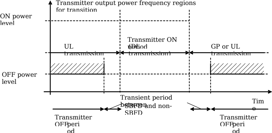 Figure 12.2.8.1-1: Example of relations between transmitter ON period, transmitter OFF period and transmitter transient period between SBFD and non-SBFD operation
The transmitter transient period for SBFD shall be measured in the transmission bandwidth configuration for SBFD DL subband, UL subband and guardband, depending on different cases as illustrated in table 12.2.8.1-1:
Table 12.2.8.1-1: Transmitter transient period between SBFD and non-SBFD operation
| | Frequency regions for transition | BS transmitter behavior during transition |
|--------------------------|----------------------------------------|-------------------------------------------------|
| SBFD symbol to DL symbol | SBFD UL subband and guardband(s) | BS transmitter OFF-to-ON |
| SBFD symbol to UL symbol | SBFD DL subband | BS transmitter ON-to-OFF |
| DL symbol to SBFD symbol | SBFD UL subband and guardband(s) | BS transmitter ON-to-OFF |
| UL symbol to SBFD symbol | SBFD DL subband | BS transmitter OFF-to-ON |For BS type 1-H this requirement shall be applied at each TAB connector supporting transmission in the operating band.
##### 12.2.8.2 Minimum requirement for BS type 1-HFor BS type 1-H , the transmitter transient period between SBFD and non-SBFD operation shall be shorter than the values listed in the minimum requirement table 12.2.8.2-1.Table 12.2.8.2-1: Minimum requirement for the transmitter transient period between SBFD and non-SBFD operation for BS type 1-H
| Transition | Transient period length (µs) |
|--------------|--------------------------------|
| OFF to ON | 10 |
| ON to OFF | 10 |
#### 12.2.9 In-channel adjacent subband leakage for SBFD
##### 12.2.9.1 General
In-channel adjacent subband leakage (ICASL) is the filtered mean power centred on the declared frequency region of SBFD UL subband within NR carrier.The requirement shall apply during the SBFD symbol .
##### 12.2.9.2 Limits and Basic limits
For SBFD operation in the unpaired spectrum, the ICASL shall be less than or equal to the value specified in table 12.2.9.2-1.Table 12.2.9.2-1: SBFD Base station ICASL absolute basic limit
| SBFD BS category / BS class | ICASL absolute basic limit |
|-------------------------------|---------------------------------|
| Category A Wide Area BS | -13 dBm/MHz |
| Category B Wide Area BS | -15 dBm/MHz |
| Medium Range BS | -25 dBm/MHz |
| Local Area BS | -32 dBm/MHz |
Table 12.2.9.2-2: Filter parameters for the UL subband
| RAT | Filter on the assigned UL subband and corresponding filter bandwidth |
|--------|------------------------------------------------------------------------|
| NR | Square (the declared bandwidth of UL subband) |
##### 12.2.9.3 Minimum requirement for BS type 1-HThe ICASL requirements are that for each TAB connector TX min cell group and each applicable basic limit in clause 12.2.9.2, the power summation emissions at the TAB connectors of the TAB connector TX min cell group shall not exceed a BS limit specified as the basic limit + X, where X = 10log 10 (N TXU,countedpercell ).
NOTE: Conformance to the in-channel adjacent subband leakage requirement can be demonstrated by meeting at least one of the following criteria as determined by the manufacturer:1) The sum of the in-channel adjacent subband leakage power measured on each TAB connector in the TAB connector TX min cell group shall be less than or equal to the limit as defined in this clause for the respective frequency span.
Or2) The in-channel adjacent subband leakage power at each TAB connector shall be less than or equal to the limit as defined in this clause for the respective frequency span, scaled by -10log 10 (n), where n is the number of TAB connectors in the TAB connector TX min cell group .
### 12.3 Conducted receiver characteristics for SBFD-capable BS
#### 12.3.1 GeneralConducted receiver characteristics are specified at the TAB connector for SBFD-capable BS type 1-H , with full complement of transceivers configured for SBFD operation in normal operating condition.
#### 12.3.2 Reference sensitivity level
##### 12.3.2.1 GeneralThe reference sensitivity power level is the minimum mean power received at the TAB connector for BS type 1-H inside the received SBFD UL subband for SBFD operation at which a throughput requirement shall be met for a specified reference measurement channel.
##### 12.3.2.2 Minimum requirements for BS type 1-H
The same requirements as clause 7.2.2 is applicable to reference sensitivity power level for SBFD operation, in which the BS channel bandwidth specified in tables shall be replaced by SBFD UL subband bandwidth.
#### 12.3.3 Dynamic range
##### 12.3.3.1 General
The dynamic range is specified as a measure of the capability of the receiver to receive a wanted signal in the presence of an interfering signal at the TAB connector for BS type 1-H inside the received SBFD UL subband for SBFD operation. In this condition, a throughput requirement shall be met for a specified reference measurement channel. The interfering signal for the dynamic range requirement is an AWGN signal.
##### 12.3.3.2 Minimum requirement for BS type 1-H
The same requirements as clause 7.3.2 is applicable to dynamic range requirement for SBFD operation, in which the BS channel bandwidth specified in tables shall be replaced by SBFD UL subband bandwidth.
#### 12.3.4 In-band selectivity and blocking for SBFD
##### 12.3.4.1 Adjacent Channel Selectivity (ACS) for SBFD
###### 12.3.4.1.1 GeneralAdjacent channel selectivity (ACS) is a measure of the receiver’s ability to receive a wanted signal at its assigned channel frequency at the TAB connector for BS type 1-H in the presence of an adjacent channel signal with a specified centre frequency offset of the interfering signal to the band edge of a victim system.NOTE: SBFD UL subband is not configured adjacent to the Radio Bandwidth edge where cross link interference from adjacent channel may appear.
###### 12.3.4.1.2 Minimum requirement for BS type 1-HFor SBFD operation, the throughput shall be ≥ 95% of the maximum throughput of the reference measurement channel, with a wanted and an interfering signal coupled to BS type 1-H TAB connector using the parameters in table 12.3.4.1.2-1 for ACS. The reference measurement channel for the wanted signal is further specified in annex A.1. The characteristics of the interfering signal is further specified in annex D.The ACS requirement is applicable outside the Base Station RF Bandwidth or Radio Bandwidth . The interfering signal offset is defined relative to the Base station RF Bandwidth edges or Radio Bandwidth edges.
Table 12.3.4.1.2-1: Base station ACS requirement for SBFD
| BS channel bandwidth of the lowest/highest carrier received (MHz) | Wanted signal mean power (dBm) (Note 1) | Interfering signal mean power (dBm) | Interfering signal centre frequency minimum offset from the lower/upper Base Station RF Bandwidth edge or sub-block edge inside a sub-block gap (MHz) | Type of interfering signal |
|--------------------------------------------------------------------------------------------------------------------------------------------------------------------------------------------------------------------------------------------------------------------------------------------------------|------------------------------------------------|-------------------------------------------------------------|-------------------------------------------------------------------------------------------------------------------------------------------------------------------------------------------------|----------------------------------------------|
| 20, 25, 30, 35, 40, 45, 50, 60, 70, 80, 90, 100 | P REFSENS + 6 dB | Wide Area BS: -28 Medium Range BS: -32 Local Area BS: -35 | ±10 | 20 MHz CP-OFDM NR signal 30 kHz SCS, 51 RBs |
| NOTE 1: P REFSENS for SBFD UL subband bandwidth depends on the BS channel bandwidth as specified in clause 12.3.2. NOTE 2: For lowest/highest carrier which is configured in DU/UD SBFD operation, the interference only applies when DL subband is adjacent to Base Station RF Bandwidth edge. | | | | |
##### 12.3.4.2 In-band blocking for SBFD
###### 12.3.4.2.1 GeneralThe in-band blocking characteristics is a measure of the receiver’s ability to receive a wanted signal at its assigned channel at the TAB connector for BS type 1-H in the presence of an unwanted interferer, which is an NR signal for general blocking.
NOTE 1: For FR1 WA BS, the in-band blocking requirements are derived based on the simulation assumption of 4GHz with 288 meters minimum distance coming from 100% grid shift between SBFD-capable BSs and neighbouring adjacent-channel TDD BSs. This NOTE shall not be interpreted as part of RF requirements.
NOTE 2: For FR1 MR BS, the in-band blocking requirements are derived based on the simulation assumption of 4GHz outdoor deployment with 167 meters minimum distance coming from 100% grid shift between SBFD-capable BSs and neighbouring adjacent-channel TDD BSs. This NOTE shall not be interpreted as part of RF requirements or in the context of indoor.NOTE 3: SBFD UL subband is not configured adjacent to the Radio Bandwidth edge where cross link interference from adjacent channel may appear.
###### 12.3.4.2.2 Minimum requirement for BS type 1-HThe throughput shall be ≥ 95% of the maximum throughput of the reference measurement channel, with a wanted and an interfering signal coupled to BS type 1-H TAB connector using the parameters in table 12.3.4.2.2-1 for general blocking for SBFD. The reference measurement channel for the wanted signal is further specified in annex A.1. The characteristics of the interfering signal is further specified in annex D.The in-band blocking requirements apply outside the Base Station RF Bandwidth or Radio Bandwidth . The interfering signal offset is defined relative to the Base Station RF Bandwidth edges or Radio Bandwidth edges.Minimum conducted requirement is defined at the TAB connector for BS type 1-H.
Table 12.3.4.2.2-1: Base station general blocking requirement
| BS channel bandwidth of the lowest/highest carrier received (MHz) | Wanted signal mean power (dBm) (Note 1) | Interfering signal mean power (dBm) | Interfering signal centre frequency minimum offset from the lower/upper Base Station RF Bandwidth edge or sub-block edge inside a sub-block gap (MHz) | Type of interfering signal |
|--------------------------------------------------------------------------------------------------------------------------------------------------------------------------------------------------------------------------------------------------------------------------------------------------------|------------------------------------------------|-------------------------------------------------------------|-------------------------------------------------------------------------------------------------------------------------------------------------------------------------------------------------|----------------------------------------------|
| 20, 25, 30, 35, 40, 45, 50, 60, 70, 80, 90, 100 | P REFSENS + 6 dB | Wide Area BS: -25 Medium Range BS: -32 Local Area BS: -35 | ±30 | 20 MHz CP-OFDM NR signal 30 kHz SCS, 51 RBs |
| NOTE 1: P REFSENS for SBFD UL subband bandwidth depends on the BS channel bandwidth as specified in clause 12.3.2. NOTE 2: For lowest/highest carrier which is configured in DU/UD SBFD operation, the interference only applies when DL subband is adjacent to Base Station RF Bandwidth edge. | | | | |
#### 12.3.5 Out-of-band blocking for SBFD
##### 12.3.5.1 General
The general requirement of out-of-band blocking for SBFD-capable BS is the same as general requirement specified in clause 7.5.1.
##### 12.3.5.2 Minimum requirement for BS type 1-H
The same requirements as specified in clause 7.5.2 shall be applied. The PREFSENS depends on the SBFD UL subband as specified in clause 12.3.2.
##### 12.3.5.3 Co-location minimum requirements for BS type 1-H
The same requirements as specified in clause 7.5.3 shall be applied. The PREFSENS depends on the SBFD UL subband as specified in clause 12.3.2.
#### 12.3.6 Receiver spurious emissions for SBFD
##### 12.3.6.1 General
The general description given in clause 7.6.1 for BS type 1-H shall be applied.
##### 12.3.6.2 Minimum requirement for BS type 1-H
The same requirements as specified in clause 7.6.4 shall be applied.
#### 12.3.7 In-channel selectivity for SBFDThe same requirements as specified in clause 7.8 shall be applied to SBFD-capable BS type 1-H during SBFD symbol , except for the note in table 7.8.2-1, table 7.8.2-1b, table 7.8.2-2, table 7.8.2-2b, table 7.8.2-2d, table 7.8.2-3 and table 7.8.2-3d, which shall be adjusted to: Wanted and interfering signal are placed adjacently around F C,SBFD,UL . The aggregated wanted and interferer signal shall be centred in the SBFD UL subband bandwidth of the wanted signal. For DU/UD case, place the wanted signal closer to the DL subband.
#### 12.3.8 In-channel adjacent subband blocking for SBFD
##### 12.3.8.1 GeneralThe in-channel adjacent subband blocking requirement is a measure of the receiver’s ability to receive a wanted signal at its assigned channel frequency at the TAB connector for SBFD-capable BS type 1-H in the presence of an interfering signal from other sector(s) and/or site(s) within the same operator’s network, which is an NR signal.
##### 12.3.8.2 Minimum requirement for BS type 1-HThe throughput shall be ≥ 95% of the maximum throughput of the reference measurement channel, with a wanted signal and an interfering signal coupled to the SBFD-capable BS type 1-H TAB connector using the parameters specified in table 12.3.8.2-1. The reference measurement channel for the wanted signal is identified in table 7.2.2-1, 7.2.2-2 and 7.2.2-3 for each SBFD UL subband bandwidth and are further specified in annex A.1. The characteristic of the interfering signal is further specified in annex D.The in-channel adjacent subband blocking requirement shall apply to SBFD UL subband bandwidth . The interfering signal(s) shall be positioned at the centre frequency of the SBFD DL subband bandwidth(s) .Minimum conducted requirement is defined at the TAB connector for *BS type 1-H.*Table 12.3.8.2-1: In-channel adjacent subband blocking requirement for BS type 1-H
| SBFD UL subband bandwidth (MHz) | Wanted signal mean power (dBm) (NOTE 1) | Interfering signal mean power (dBm) (NOTE 5) | SBFD UD/UD or DUD case | Interfering signal centre frequency/frequencies | Type of interfering signal(s) (NOTE 2, 3, 4) |
|-----------------------------------------------------------------------------------------------------------------------------------------------------------------------------------------------------------------------------------------------------------------------------------------------------------------------------------------------------------------------------------------------------------------------------------------------------------------------------------------------------------------------------------------------------------------------------------------------------------------------------------------------------------------------------------------------------------------------------------------------------------------------------------------------------------------------------------------------------------------------------------------------------------------------------------------------------------------------------------------------------------------------------------------------------------------------------------------------------------------------------------------------------------------------------------------------------------------------------------------------------------------------------------------------------------------------------------------------------------------------------------------------------|--------------------------------------------|-------------------------------------------------------------|--------------------------|---------------------------------------------------|--------------------------------------------------------------------------|
| 10, 15, 20, 25, 30, 35, 40, 45, 50, 60, 70, 80, 90 | P REFSENS + 6 dB | Wide Area BS: -28 Medium Range BS: -32 Local Area BS: -34 | DU or UD | F C,SBFD,DL | CP-OFDM NR signal 30 kHz SCS, BW = X (in the unit of RB) |
| 10, 15, 20, 25, 30, 35, 40, 45, 50, 60, 70, 80, 90 | | | DUD | F C,SBFD,DL,1 F C,SBFD,DL,2 | CP-OFDM NR signal 30 kHz SCS, BW1 = X1 and BW2 = X2 (in the unit of RB) |
| NOTE 1: P REFSENS depends on the SBFD UL subband bandwidth as specified in clause 12.3.2. NOTE 2: For DU or UD case, interfering signal is placed at F C,SBFD,DL . For DUD case, two interfering signals are placed at F C,SBFD,DL,1 and F C,SBFD,DL,2 , respectively, interfering signal mean power is the total power of the two interfering signals and the two interfering signals have the same power density. NOTE 3: For DU or UD case, X is the largest transmission bandwidth configuration as specified in table 5.3.2-1 that is not larger than N RB, SBFD, DL . For DUD case, X1 is the largest transmission bandwidth configuration as specified in table 5.3.2-1 that is not larger than N RB, SBFD, DL,1 and X2 is the largest transmission bandwidth configuration as specified in table 5.3.2-1 that is not larger than N RB, SBFD, DL,2 . NOTE 4: In case the SBFD BS is configured with intra-band carrier aggregation, the set of interfering signals consists of the interfering signal(s) in this table and the signals from other intra-band contiguous carrier(s) operated in non-SBFD operation. The power spectral density of each interfering signal is set to be the same level. NOTE 5: For FR1 WA BS, in-channel adjacent subband blocking requirement assumes 80 dBc coupling loss between interfering BS transmitter and SBFD BS receiver. | | | | | |
### 12.4 Conducted performance requirements for SBFD-capable BS
#### 12.4.1 General
##### 12.4.1.1 Scope and definitionsConducted performance requirements specify the ability of the SBFD-capable BS type 1-H to correctly demodulate signals in various conditions and configurations. Conducted performance requirements are specified at the TAB connector(s) (for SBFD-capable BS type 1-H ).
Conducted performance requirements for the BS are specified for the fixed reference channels defined in annex A and the propagation conditions in annex G. The requirements only apply to those FRCs that are supported by the base station.Unless stated otherwise, performance requirements apply for a single carrier only. Performance requirements for a BS supporting carrier aggregation are defined in terms of single carrier requirements.
The SNR used in this clause is specified based on a single carrier and defined as:
SNR = S / N
Where:S is the total signal energy in the slot on a single TAB connector (for SBFD-capable BS type 1-H ).N is the noise energy in a bandwidth corresponding to the transmission bandwidth over the same duration where signal energy exists on a single TAB connector (for SBFD-capable BS type 1-H ).
##### 12.4.1.2 Void
#### 12.4.2 Performance requirements for PUSCH
##### 12.4.2.1 Requirements for PUSCH with transform precoding disabledThe same general description and requirements as clause 8.2.1 is appliable to requirements for PUSCH with transform precoding disabled, where the PUSCH received at the TAB connector for SBFD-capable BS type 1-H inside the received SBFD UL subband for SBFD operation, and the BS channel bandwidth specified in the tables shall be replaced by SBFD UL subband bandwidth.
##### 12.4.2.2 Requirements for PUSCH with transform precoding enabledThe same general description and requirements as clause 8.2.2 is appliable to requirements for PUSCH with transform precoding disabled, where the PUSCH received at the TAB connector for SBFD-capable BS type 1-H inside the received SBFD UL subband for SBFD operation, and the BS channel bandwidth specified in the tables shall be replaced by SBFD UL subband bandwidth.
##### 12.4.2.3 Requirements for UCI multiplexed on PUSCHThe same general description and requirements as clause 8.2.3 is appliable to requirements for UCI multiplexed on PUSCH, where the UCI multiplexed on PUSCH received at the TAB connector for SBFD-capable BS type 1-H inside the received SBFD UL subband for SBFD operation, and the BS channel bandwidth specified in the tables shall be replaced by SBFD UL subband bandwidth.
##### 12.4.2.4 Enhanced performance requirements for PUSCH with synchronous interferenceThe same general description and requirements as clause 8.2.16 is appliable to requirements for enhanced performance requirements for PUSCH with synchronous interference, where the PUSCH received at the TAB connector for SBFD-capable BS type 1-H inside the received SBFD UL subband for SBFD operation, and the BS channel bandwidth specified in the tables shall be replaced by SBFD UL subband bandwidth.
##### 12.4.2.5 Requirements for PUSCH with UL resource muting
###### 12.4.2.5.1 GeneralThe performance requirement of PUSCH with UL resource muting is determined by a minimum required throughput for a given SNR, where the PUSCH received at the TAB connector for BS type 1-H inside the received SBFD UL subband for SBFD operation. The required throughput is expressed as a fraction of maximum throughput for the FRCs listed in annex A. The performance requirements assume HARQ retransmissions.
Table: 12.4.2.5.1-1 Test parameters for testing PUSCH with UL resource muting
| Parameter | | Value | | | |
|--------------------------------------------------------------------------------------------------------------------------------------------------------------------------------------------------------------------------------------------------------------------------------------------------------------------------------------------------------------------------------------------------------------------------------------------------------------------------------------------------------------------------------------------------------------------------------------------------------------------------------------------------------------------------------------------------------------------------------------------|--------------------------------------------|------------------------------------------------------------------------------------------------------------|------------------------------------------------------------------------------------------------------------|------------------------------------------------------------------------------------------------------------|------------------------------------------------------------------------------------------------------------|
| | | Tested signal | Interferer 1 (Note 1) | Interferer 1 (Note 1) | Interferer 2 (Note 1) |
| Transform precoding | Transform precoding | Disabled | Disabled | Disabled | Disabled |
| Default TDD UL-DL pattern (Note 2, Note 3) | Default TDD UL-DL pattern (Note 2, Note 3) | 30 kHz SCS: XXXXXXXXUU | 30 kHz SCS: XXXXXXXXUU | 30 kHz SCS: XXXXXXXXUU | 30 kHz SCS: XXXXXXXXUU |
| INR (dB, Note 4) | INR (dB, Note 4) | N/A | 9 | -1 | -1 |
| Interference Model (Note 5) | Interference Model (Note 5) | N/A | As specified in B.9.2 | As specified in B.9.2 | As specified in B.9.2 |
| HARQ | Maximum number of HARQ transmissions | 4 | N/A | N/A | N/A |
| HARQ | RV sequence | 0, 2, 3, 1 | N/A | N/A | N/A |
| DM-RS | DM-RS configuration type | 1 | 1 | 1 | 1 |
| DM-RS | DM-RS duration | single-symbol DM-RS | single-symbol DM-RS | single-symbol DM-RS | single-symbol DM-RS |
| DM-RS | Additional DM-RS position | pos1 | pos1 | pos1 | pos1 |
| DM-RS | Number of DM-RS CDM group(s) without data | 2 | 2 | 2 | 2 |
| DM-RS | Ratio of PUSCH EPRE to DM-RS EPRE | -3 dB | -3 dB | -3 dB | -3 dB |
| DM-RS | DM-RS port | {0} | {0} | {0} | {0} |
| DM-RS | DM-RS sequence generation | N ID 0 =0, n SCID =0 | N ID 0 =1, n SCID =0 | | N ID 0 =2, n SCID =0 |
| Time domain resource assignment | PUSCH mapping type | A, B | A, B | A, B | A, B |
| Time domain resource assignment | Start symbol | 0 | 0 | 0 | 0 |
| Time domain resource assignment | Allocation length | 14 | 14 | 14 | 14 |
| Muting resource assignement | Symbol positionng | 4 for mapping type A, 2 for mapping type B | | | |
| Muting resource assignement | CombOffset | 0 | 0 | 0 | 0 |
| Frequency domain resource assignment | RB assignment | 51 PRBs on the lower edge of full applicable bandwidth in X slots and full applicable bandwidth in U slots | 51 PRBs on the lower edge of full applicable bandwidth in X slots and full applicable bandwidth in U slots | 51 PRBs on the lower edge of full applicable bandwidth in X slots and full applicable bandwidth in U slots | 51 PRBs on the lower edge of full applicable bandwidth in X slots and full applicable bandwidth in U slots |
| Frequency domain resource assignment | Frequency hopping | Disabled | Disabled | Disabled | Disabled |
| Code block group based PUSCH transmission | Code block group based PUSCH transmission | Disabled | Disabled | Disabled | Disabled |
| NOTE 1: Two explicit interferers are modelled for tests with 2, 4 or 8 RX antennas NOTE 2: The same requirements are applicable to TDD with different UL-DL patterns. NOTE 3: The sub-band PUSCH transmission start from the first X slot (TDD-UL-DL-ConfigCommon = ‘F’ for X slots). All symbols in X slot use sub-band PUSCH transmission NOTE 4: The respective received energy of each interferer relative to noise is defined by its associated INR value as specified in Annex B.9.1. The INR value is derived by only considering inter-site gNB-gNB interference using a link-budget method. Self-interference and intra-site inter-sector interference are not taken into account NOTE 5: All cells are time-synchronous. | | | | | |
###### 12.4.2.5.2 Minimum requirements
The throughput shall be equal to or larger than the fraction of maximum throughput for the FRCs stated in tables 12.4.2.5.2-1 at the given SNR measured only on X slots. FRCs are defined in annex A.
Table 12.4.2.5.2-1: Minimum requirements for PUSCH with 70% of maximum throughput, Type A, 40 MHz channel bandwidth, 30 kHz SCS
| Number of TX antennas (Note 1) | Number of RX antennas (Note 1) | Cyclic prefix | Propagation conditions and correlation matrix (Annex G) (Note 2) | | Fraction of maximum throughput | FRC (Annex A) | Additional DM-RS position | SNR (dB) |
|-----------------------------------------------------------------------------------------------------------------------------------------------------------------------------------------------|----------------------------------|-----------------|---------------------------------------------------------------------|---------------|----------------------------------|-----------------|-----------------------------|-------------|
| Number of TX antennas (Note 1) | Number of RX antennas (Note 1) | Cyclic prefix | Tested signal | Interferers | Fraction of maximum throughput | FRC (Annex A) | Additional DM-RS position | |
| 1 | 2 | Normal | TDLC300-100 Low | TDLC300-0 Low | 70% | G-FR1-A4-15 | pos1 | 16.5 |
| 1 | 4 | Normal | TDLC300-100 Low | TDLC300-0 Low | 70% | G-FR1-A4-15 | pos1 | 10.5 |
| 1 | 8 | Normal | TDLC300-100 Low | TDLC300-0 Low | 70% | G-FR1-A4-15 | pos1 | 6.5 |
| Note 1: Antenna configuration applies for each of the tested signal and interferers. Note 2: The propagation conditions for the tested signal and interferers are statistically independent. | | | | | | | | |
Table 12.4.2.5.2-2: Minimum requirements for PUSCH with 70% of maximum throughput, Type B, 40 MHz channel bandwidth, 30 kHz SCS
| Number of TX antennas (Note 1) | Number of RX antennas (Note 1) | Cyclic prefix | Propagation conditions and correlation matrix (Annex G) (Note 2) | Propagation conditions and correlation matrix (Annex G) (Note 2) | Fraction of maximum throughput | FRC (Annex A) | Additional DM-RS position | SNR (dB) |
|----------------------------------------------------------------------------------------------------------------------------------------------------------------------------------------------|----------------------------------|-----------------|---------------------------------------------------------------------|---------------------------------------------------------------------|----------------------------------|-----------------|-----------------------------|-------------|
| Number of TX antennas (Note 1) | Number of RX antennas (Note 1) | Cyclic prefix | Tested signal | Interferers | Fraction of maximum throughput | FRC (Annex A) | Additional DM-RS position | |
| 1 | 2 | Normal | TDLC300-100 Low | TDLC300-0 Low | 70% | G-FR1-A4-15 | pos1 | 16.4 |
| 1 | 4 | Normal | TDLC300-100 Low | TDLC300-0 Low | 70% | G-FR1-A4-15 | pos1 | 9.8 |
| 1 | 8 | Normal | TDLC300-100 Low | TDLC300-0 Low | 70% | G-FR1-A4-15 | pos1 | 6.6 |
| Note 1: Antenna configuration applies for each of the tested signal and interferers. Note 2: The propagation conditions for the tested signal and interferers are statistically independent | | | | | | | | |
#### 12.4.3 Performance requirements for PUCCH
##### 12.4.3.1 DTX to ACK probabilityThe same general description and requirements as clause 8.3.1 is appliable to requirements for DTX to ACK probability, where the UCI multiplexed on PUSCH received at the TAB connector for SBFD-capable BS type 1-H inside the received SBFD UL subband for SBFD operation, and the BS channel bandwidth specified in the tables shall be replaced by SBFD UL subband bandwidth.
##### 12.4.3.2 Performance requirements for PUCCH format 0The same general description and requirements as clause 8.3.2 is appliable to requirements for PUCCH format 0, where the PUCCH format 0 received at the TAB connector for SBFD-capable BS type 1-H inside the received SBFD UL subband for SBFD operation, and the BS channel bandwidth specified in the tables shall be replaced by SBFD UL subband bandwidth.
##### 12.4.3.3 Performance requirements for PUCCH format 1The same general description and requirements as clause 8.3.3 is appliable to requirements for PUCCH format 1, where the PUCCH format 1 received at the TAB connector for SBFD-capable BS type 1-H inside the received SBFD UL subband for SBFD operation, and the BS channel bandwidth specified in the tables shall be replaced by SBFD UL subband bandwidth.
##### 12.4.3.4 Performance requirements for PUCCH format 2The same general description and requirements as clause 8.3.4 is appliable to requirements for PUCCH format 2, where the PUCCH format 2 received at the TAB connector for SBFD-capable BS type 1-H inside the received SBFD UL subband for SBFD operation, and the BS channel bandwidth specified in the tables shall be replaced by SBFD UL subband bandwidth.
##### 12.4.3.5 Performance requirements for PUCCH format 3The same general description and requirements as clause 8.3.5 is appliable to requirements for PUCCH format 3, where the PUCCH format 3 received at the TAB connector for SBFD-capable BS type 1-H inside the received SBFD UL subband for SBFD operation, and the BS channel bandwidth specified in the tables shall be replaced by SBFD UL subband bandwidth.
##### 12.4.3.6 Performance requirements for PUCCH format 4The same general description and requirements as clause 8.3.6 is appliable to requirements for PUCCH format 4, where the PUCCH format 4 received at the TAB connector for SBFD-capable BS type 1-H inside the received SBFD UL subband for SBFD operation, and the BS channel bandwidth specified in the tables shall be replaced by SBFD UL subband bandwidth.
##### 12.4.3.7 Performance requirements for multi-slot PUCCHThe same general description and requirements as clause 8.3.7 is appliable to requirements for multi-slot PUCCH format 1, where the multi-slot PUCCH format 1 received at the TAB connector for SBFD-capable BS type 1-H inside the received SBFD UL subband for SBFD operation, and the BS channel bandwidth specified in the tables shall be replaced by SBFD UL subband bandwidth.
#### 12.4.4 Performance requirements for PRACHThe same general description and requirements as clause 8.4.1 to clause 8.4.2.2 is appliable to requirements for PRACH, where the PRACH received at the TAB connector for SBFD-capable BS type 1-H inside the received SBFD UL subband for SBFD operation, and the BS channel bandwidth specified in the tables shall be replaced by SBFD UL subband bandwidth.
### 12.5 Radiated transmitter characteristics for SBFD-capable BS
#### 12.5.1 GeneralRadiated transmitter characteristics requirements apply on the SBFD-capable BS type 1-H , BS type 1-O or BS type 2-O including all its functional components active and for SBFD operation.
#### 12.5.2 Radiated transmit power for SBFD
##### 12.5.2.1 GeneralThe BS radiated transmit power for SBFD operation is specified over SBFD symbol , in which the EIRP for SBFD symbol may be different from the EIRP for transmitter ON period as specified in clause 9.2.1.
##### 12.5.2.2 Minimum requirement for BS type 1-H and BS type 1-O
The same requirement as clause 9.2.2 is applicable to BS radiated transmit power requirement for SBFD operation.
##### 12.5.2.3 Minimum requirement for BS type 2-O
The same requirement as clause 9.2.3 is applicable to BS radiated transmit power requirement for SBFD operation.
#### 12.5.3 OTA base station output power for SBFD
##### 12.5.3.1 GeneralThe OTA base station output power for SBFD operation is specified over SBFD symbol , in which the TRP for SBFD symbol may be different from the TRP for transmitter ON period as specified in clause 9.3.1.
##### 12.5.3.2 Minimum requirement for BS type 1-O
The same requirement as clause 9.3.2 is applicable to OTA base station output power requirement for SBFD operation.
##### 12.5.3.3 Minimum requirement for BS type 2-O
The same requirement as clause 9.3.3 is applicable to OTA base station output power requirement for SBFD operation.
#### 12.5.4 OTA output power dynamics for SBFD
##### 12.5.4.1 GeneralThe requirements in clause 12.5.4 apply during SBFD symbol . Transmit signal quality (as specified in clause 12.5.6) shall be maintained for the output power dynamics requirements of this clause.The OTA output power requirements are directional requirements and apply to the beam peak directions over the OTA peak directions set .
##### 12.5.4.2 OTA RE power control dynamic range for SBFD
###### 12.5.4.2.1 GeneralThe RE power control dynamic range for SBFD operation is the difference between the power of an RE and the average RE power for a BS at maximum output power (P SBFD,max,c,TABC ) during SBFD symbol for a specified reference condition.For BS type 1-H this requirement shall apply at each TAB connector supporting transmission in the operating band .
###### 12.5.4.2.2 Minimum requirement for BS type 1-OThe OTA RE power control dynamic range for SBFD operation is specified the same as the conducted RE power control dynamic range requirement for BS type 1-H in clause 12.2.3.2.
##### 12.5.4.3 OTA total power dynamic range for SBFD
###### 12.5.4.3.1 General
The BS total power dynamic range for SBFD is the difference between the maximum and the minimum transmit power of an OFDM symbol for a specified reference condition.This requirement shall apply at each RIB supporting transmission in the operating band .NOTE 1: The upper limit of the OTA total power dynamic range for SBFD is the BS maximum carrier EIRP (P max,c,EIRP ) when transmitting on all DL RBs in transmission bandwidth configuration for SBFD at maximum output power. The lower limit of the OTA total power dynamic range is the average EIRP for single RB transmission in the same direction using the same beam. The OFDM symbol carries PDSCH and not contain RS or SSB.
###### 12.5.4.3.2 Minimum requirement for BS type 1-O and BS type 2-OThe OTA total power dynamic range minimum requirement for each NR carrier shall be larger than or equal to the level calculated as 10log 10 (N RB,SBFD,DL ) if one SBFD DL subband is configured, i.e., DU or UD pattern, and as 10log 10 (N RB,SBFD,DL,1 + N RB,SBFD,DL,2 ) if two SBFD DL subbands are configured, i.e., DUD pattern.
#### 12.5.5 OTA transmit ON/OFF power for SBFD
##### 12.5.5.1 OTA transmitter OFF power for SBFD
###### 12.5.5.1.1 General
The general description for OTA transmitter OFF power as clause 9.5 shall be applied.
###### 12.5.5.1.2 Minimum requirement for BS type 1-O and BS type 2-O
For the OTA transmitter OFF power requirements for non-SBFD symbols, the same requirement as specified in clause 9.5 shall be applied. Requirement is not applicable for SBFD symbols.
#### 12.5.6 OTA transmitted signal quality for SBFD
##### 12.5.6.1 General
The general description for OTA transmitted signal quality as clause 9.6 shall be applied.
##### 12.5.6.2 Minimum requirement for BS type 1-O and BS type 2-O
For frequency error, modulation quality (EVM) and time alignment error (TAE), the same requirements as specified in clause 9.6 shall be applied.
#### 12.5.7 OTA unwanted emissions for SBFD
##### 12.5.7.1 General
The general description for OTA unwanted emissions as clause 9.7 shall be applied.
##### 12.5.7.2 Minimum requirement for BS type 1-O and BS type 2-O
For OTA occupied bandwidth, OTA adjacent channel leakage power ratio (ACLR), OTA operating band unwanted emissions (OBUE), and OTA transmitter spurious emissions the same requirements as specified in clause 9.7 shall be applied.
Requirements related with multi-band and non-contiguous spectrum are not applied to SBFD.
#### 12.5.8 OTA Transmitter intermodulation for SBFD
##### 12.5.8.1 General
The general description for OTA transmitter intermodulation as clause 9.8 shall be applied.
##### 12.5.8.2 Minimum requirements for BS type 1-O and BS type 2-O
For the OTA transmitter intermodulation requirement, the same requirement as specified in clause 9.8 shall be applied. Receiver requirement is not specified during the OTA transmitter intermodulation test.
#### 12.5.9 OTA spatial emission for SBFD
##### 12.5.9.1 GeneralOTA spatial emission requirements apply to SBFD-capable BS during SBFD symbol .
##### 12.5.9.2 Protection of FSS ULFor SBFD-capable BS type 1-H and BS type 1-O operating in band n104 during SBFD symbol , the Expected EIRP (EEIRP) in the frequency range 6425 – 7075 MHz, shall not exceed the limits specified in table 9.9.2.2-1.
#### 12.5.10 OTA transient period between SBFD and non-SBFD operation
##### 12.5.10.1 GeneralThe transmitter transient period between SBFD and non-SBFD operation is the time period during which the transmitter is changing from the transmitter OFF period to the transmitter ON period or vice versa. The transmitter transient period between SBFD and non-SBFD operation is illustrated in figure 12.5.10.1-1.
Transmitter output power frequency regions for transition
Figure 12.2.8.1-1: Example of relations between transmitter ON period, transmitter OFF period and transmitter transient period between SBFD and non-SBFD operation
The transmitter transient period for SBFD shall be measured in the transmission bandwidth configuration for SBFD DL subband, UL subband and guardband, depending on different cases as illustrated in table 12.2.8.1-1:
Table 12.2.8.1-1: Transmitter transient period between SBFD and non-SBFD operation
| | Frequency regions for transition | BS transmitter behavior during transition |
|--------------------------|----------------------------------------|-------------------------------------------------|
| SBFD symbol to DL symbol | SBFD UL subband and guardband(s) | BS transmitter OFF-to-ON |
| SBFD symbol to UL symbol | SBFD DL subband | BS transmitter ON-to-OFF |
| DL symbol to SBFD symbol | SBFD UL subband and guardband(s) | BS transmitter ON-to-OFF |
| UL symbol to SBFD symbol | SBFD DL subband | BS transmitter OFF-to-ON |For BS type 1-H this requirement shall be applied at each TAB connector supporting transmission in the operating band.
##### 12.2.8.2 Minimum requirement for BS type 1-HFor BS type 1-H , the transmitter transient period between SBFD and non-SBFD operation shall be shorter than the values listed in the minimum requirement table 12.2.8.2-1.Table 12.2.8.2-1: Minimum requirement for the transmitter transient period between SBFD and non-SBFD operation for BS type 1-H
| Transition | Transient period length (µs) |
|--------------|--------------------------------|
| OFF to ON | 10 |
| ON to OFF | 10 |
#### 12.2.9 In-channel adjacent subband leakage for SBFD
##### 12.2.9.1 General
In-channel adjacent subband leakage (ICASL) is the filtered mean power centred on the declared frequency region of SBFD UL subband within NR carrier.The requirement shall apply during the SBFD symbol .
##### 12.2.9.2 Limits and Basic limits
For SBFD operation in the unpaired spectrum, the ICASL shall be less than or equal to the value specified in table 12.2.9.2-1.Table 12.2.9.2-1: SBFD Base station ICASL absolute basic limit
| SBFD BS category / BS class | ICASL absolute basic limit |
|-------------------------------|---------------------------------|
| Category A Wide Area BS | -13 dBm/MHz |
| Category B Wide Area BS | -15 dBm/MHz |
| Medium Range BS | -25 dBm/MHz |
| Local Area BS | -32 dBm/MHz |
Table 12.2.9.2-2: Filter parameters for the UL subband
| RAT | Filter on the assigned UL subband and corresponding filter bandwidth |
|--------|------------------------------------------------------------------------|
| NR | Square (the declared bandwidth of UL subband) |
##### 12.2.9.3 Minimum requirement for BS type 1-HThe ICASL requirements are that for each TAB connector TX min cell group and each applicable basic limit in clause 12.2.9.2, the power summation emissions at the TAB connectors of the TAB connector TX min cell group shall not exceed a BS limit specified as the basic limit + X, where X = 10log 10 (N TXU,countedpercell ).
NOTE: Conformance to the in-channel adjacent subband leakage requirement can be demonstrated by meeting at least one of the following criteria as determined by the manufacturer:1) The sum of the in-channel adjacent subband leakage power measured on each TAB connector in the TAB connector TX min cell group shall be less than or equal to the limit as defined in this clause for the respective frequency span.
Or2) The in-channel adjacent subband leakage power at each TAB connector shall be less than or equal to the limit as defined in this clause for the respective frequency span, scaled by -10log 10 (n), where n is the number of TAB connectors in the TAB connector TX min cell group .
### 12.3 Conducted receiver characteristics for SBFD-capable BS
#### 12.3.1 GeneralConducted receiver characteristics are specified at the TAB connector for SBFD-capable BS type 1-H , with full complement of transceivers configured for SBFD operation in normal operating condition.
#### 12.3.2 Reference sensitivity level
##### 12.3.2.1 GeneralThe reference sensitivity power level is the minimum mean power received at the TAB connector for BS type 1-H inside the received SBFD UL subband for SBFD operation at which a throughput requirement shall be met for a specified reference measurement channel.
##### 12.3.2.2 Minimum requirements for BS type 1-H
The same requirements as clause 7.2.2 is applicable to reference sensitivity power level for SBFD operation, in which the BS channel bandwidth specified in tables shall be replaced by SBFD UL subband bandwidth.
#### 12.3.3 Dynamic range
##### 12.3.3.1 General
The dynamic range is specified as a measure of the capability of the receiver to receive a wanted signal in the presence of an interfering signal at the TAB connector for BS type 1-H inside the received SBFD UL subband for SBFD operation. In this condition, a throughput requirement shall be met for a specified reference measurement channel. The interfering signal for the dynamic range requirement is an AWGN signal.
##### 12.3.3.2 Minimum requirement for BS type 1-H
The same requirements as clause 7.3.2 is applicable to dynamic range requirement for SBFD operation, in which the BS channel bandwidth specified in tables shall be replaced by SBFD UL subband bandwidth.
#### 12.3.4 In-band selectivity and blocking for SBFD
##### 12.3.4.1 Adjacent Channel Selectivity (ACS) for SBFD
###### 12.3.4.1.1 GeneralAdjacent channel selectivity (ACS) is a measure of the receiver’s ability to receive a wanted signal at its assigned channel frequency at the TAB connector for BS type 1-H in the presence of an adjacent channel signal with a specified centre frequency offset of the interfering signal to the band edge of a victim system.NOTE: SBFD UL subband is not configured adjacent to the Radio Bandwidth edge where cross link interference from adjacent channel may appear.
###### 12.3.4.1.2 Minimum requirement for BS type 1-HFor SBFD operation, the throughput shall be ≥ 95% of the maximum throughput of the reference measurement channel, with a wanted and an interfering signal coupled to BS type 1-H TAB connector using the parameters in table 12.3.4.1.2-1 for ACS. The reference measurement channel for the wanted signal is further specified in annex A.1. The characteristics of the interfering signal is further specified in annex D.The ACS requirement is applicable outside the Base Station RF Bandwidth or Radio Bandwidth . The interfering signal offset is defined relative to the Base station RF Bandwidth edges or Radio Bandwidth edges.
Table 12.3.4.1.2-1: Base station ACS requirement for SBFD
| BS channel bandwidth of the lowest/highest carrier received (MHz) | Wanted signal mean power (dBm) (Note 1) | Interfering signal mean power (dBm) | Interfering signal centre frequency minimum offset from the lower/upper Base Station RF Bandwidth edge or sub-block edge inside a sub-block gap (MHz) | Type of interfering signal |
|--------------------------------------------------------------------------------------------------------------------------------------------------------------------------------------------------------------------------------------------------------------------------------------------------------|------------------------------------------------|-------------------------------------------------------------|-------------------------------------------------------------------------------------------------------------------------------------------------------------------------------------------------|----------------------------------------------|
| 20, 25, 30, 35, 40, 45, 50, 60, 70, 80, 90, 100 | P REFSENS + 6 dB | Wide Area BS: -28 Medium Range BS: -32 Local Area BS: -35 | ±10 | 20 MHz CP-OFDM NR signal 30 kHz SCS, 51 RBs |
| NOTE 1: P REFSENS for SBFD UL subband bandwidth depends on the BS channel bandwidth as specified in clause 12.3.2. NOTE 2: For lowest/highest carrier which is configured in DU/UD SBFD operation, the interference only applies when DL subband is adjacent to Base Station RF Bandwidth edge. | | | | |
##### 12.3.4.2 In-band blocking for SBFD
###### 12.3.4.2.1 GeneralThe in-band blocking characteristics is a measure of the receiver’s ability to receive a wanted signal at its assigned channel at the TAB connector for BS type 1-H in the presence of an unwanted interferer, which is an NR signal for general blocking.
NOTE 1: For FR1 WA BS, the in-band blocking requirements are derived based on the simulation assumption of 4GHz with 288 meters minimum distance coming from 100% grid shift between SBFD-capable BSs and neighbouring adjacent-channel TDD BSs. This NOTE shall not be interpreted as part of RF requirements.
NOTE 2: For FR1 MR BS, the in-band blocking requirements are derived based on the simulation assumption of 4GHz outdoor deployment with 167 meters minimum distance coming from 100% grid shift between SBFD-capable BSs and neighbouring adjacent-channel TDD BSs. This NOTE shall not be interpreted as part of RF requirements or in the context of indoor.NOTE 3: SBFD UL subband is not configured adjacent to the Radio Bandwidth edge where cross link interference from adjacent channel may appear.
###### 12.3.4.2.2 Minimum requirement for BS type 1-HThe throughput shall be ≥ 95% of the maximum throughput of the reference measurement channel, with a wanted and an interfering signal coupled to BS type 1-H TAB connector using the parameters in table 12.3.4.2.2-1 for general blocking for SBFD. The reference measurement channel for the wanted signal is further specified in annex A.1. The characteristics of the interfering signal is further specified in annex D.The in-band blocking requirements apply outside the Base Station RF Bandwidth or Radio Bandwidth . The interfering signal offset is defined relative to the Base Station RF Bandwidth edges or Radio Bandwidth edges.Minimum conducted requirement is defined at the TAB connector for BS type 1-H.
Table 12.3.4.2.2-1: Base station general blocking requirement
| BS channel bandwidth of the lowest/highest carrier received (MHz) | Wanted signal mean power (dBm) (Note 1) | Interfering signal mean power (dBm) | Interfering signal centre frequency minimum offset from the lower/upper Base Station RF Bandwidth edge or sub-block edge inside a sub-block gap (MHz) | Type of interfering signal |
|--------------------------------------------------------------------------------------------------------------------------------------------------------------------------------------------------------------------------------------------------------------------------------------------------------|------------------------------------------------|-------------------------------------------------------------|-------------------------------------------------------------------------------------------------------------------------------------------------------------------------------------------------|----------------------------------------------|
| 20, 25, 30, 35, 40, 45, 50, 60, 70, 80, 90, 100 | P REFSENS + 6 dB | Wide Area BS: -25 Medium Range BS: -32 Local Area BS: -35 | ±30 | 20 MHz CP-OFDM NR signal 30 kHz SCS, 51 RBs |
| NOTE 1: P REFSENS for SBFD UL subband bandwidth depends on the BS channel bandwidth as specified in clause 12.3.2. NOTE 2: For lowest/highest carrier which is configured in DU/UD SBFD operation, the interference only applies when DL subband is adjacent to Base Station RF Bandwidth edge. | | | | |
#### 12.3.5 Out-of-band blocking for SBFD
##### 12.3.5.1 General
The general requirement of out-of-band blocking for SBFD-capable BS is the same as general requirement specified in clause 7.5.1.
##### 12.3.5.2 Minimum requirement for BS type 1-H
The same requirements as specified in clause 7.5.2 shall be applied. The PREFSENS depends on the SBFD UL subband as specified in clause 12.3.2.
##### 12.3.5.3 Co-location minimum requirements for BS type 1-H
The same requirements as specified in clause 7.5.3 shall be applied. The PREFSENS depends on the SBFD UL subband as specified in clause 12.3.2.
#### 12.3.6 Receiver spurious emissions for SBFD
##### 12.3.6.1 General
The general description given in clause 7.6.1 for BS type 1-H shall be applied.
##### 12.3.6.2 Minimum requirement for BS type 1-H
The same requirements as specified in clause 7.6.4 shall be applied.
#### 12.3.7 In-channel selectivity for SBFDThe same requirements as specified in clause 7.8 shall be applied to SBFD-capable BS type 1-H during SBFD symbol , except for the note in table 7.8.2-1, table 7.8.2-1b, table 7.8.2-2, table 7.8.2-2b, table 7.8.2-2d, table 7.8.2-3 and table 7.8.2-3d, which shall be adjusted to: Wanted and interfering signal are placed adjacently around F C,SBFD,UL . The aggregated wanted and interferer signal shall be centred in the SBFD UL subband bandwidth of the wanted signal. For DU/UD case, place the wanted signal closer to the DL subband.
#### 12.3.8 In-channel adjacent subband blocking for SBFD
##### 12.3.8.1 GeneralThe in-channel adjacent subband blocking requirement is a measure of the receiver’s ability to receive a wanted signal at its assigned channel frequency at the TAB connector for SBFD-capable BS type 1-H in the presence of an interfering signal from other sector(s) and/or site(s) within the same operator’s network, which is an NR signal.
##### 12.3.8.2 Minimum requirement for BS type 1-HThe throughput shall be ≥ 95% of the maximum throughput of the reference measurement channel, with a wanted signal and an interfering signal coupled to the SBFD-capable BS type 1-H TAB connector using the parameters specified in table 12.3.8.2-1. The reference measurement channel for the wanted signal is identified in table 7.2.2-1, 7.2.2-2 and 7.2.2-3 for each SBFD UL subband bandwidth and are further specified in annex A.1. The characteristic of the interfering signal is further specified in annex D.The in-channel adjacent subband blocking requirement shall apply to SBFD UL subband bandwidth . The interfering signal(s) shall be positioned at the centre frequency of the SBFD DL subband bandwidth(s) .Minimum conducted requirement is defined at the TAB connector for *BS type 1-H.*Table 12.3.8.2-1: In-channel adjacent subband blocking requirement for BS type 1-H
| SBFD UL subband bandwidth (MHz) | Wanted signal mean power (dBm) (NOTE 1) | Interfering signal mean power (dBm) (NOTE 5) | SBFD UD/UD or DUD case | Interfering signal centre frequency/frequencies | Type of interfering signal(s) (NOTE 2, 3, 4) |
|-----------------------------------------------------------------------------------------------------------------------------------------------------------------------------------------------------------------------------------------------------------------------------------------------------------------------------------------------------------------------------------------------------------------------------------------------------------------------------------------------------------------------------------------------------------------------------------------------------------------------------------------------------------------------------------------------------------------------------------------------------------------------------------------------------------------------------------------------------------------------------------------------------------------------------------------------------------------------------------------------------------------------------------------------------------------------------------------------------------------------------------------------------------------------------------------------------------------------------------------------------------------------------------------------------------------------------------------------------------------------------------------------------|--------------------------------------------|-------------------------------------------------------------|--------------------------|---------------------------------------------------|--------------------------------------------------------------------------|
| 10, 15, 20, 25, 30, 35, 40, 45, 50, 60, 70, 80, 90 | P REFSENS + 6 dB | Wide Area BS: -28 Medium Range BS: -32 Local Area BS: -34 | DU or UD | F C,SBFD,DL | CP-OFDM NR signal 30 kHz SCS, BW = X (in the unit of RB) |
| 10, 15, 20, 25, 30, 35, 40, 45, 50, 60, 70, 80, 90 | | | DUD | F C,SBFD,DL,1 F C,SBFD,DL,2 | CP-OFDM NR signal 30 kHz SCS, BW1 = X1 and BW2 = X2 (in the unit of RB) |
| NOTE 1: P REFSENS depends on the SBFD UL subband bandwidth as specified in clause 12.3.2. NOTE 2: For DU or UD case, interfering signal is placed at F C,SBFD,DL . For DUD case, two interfering signals are placed at F C,SBFD,DL,1 and F C,SBFD,DL,2 , respectively, interfering signal mean power is the total power of the two interfering signals and the two interfering signals have the same power density. NOTE 3: For DU or UD case, X is the largest transmission bandwidth configuration as specified in table 5.3.2-1 that is not larger than N RB, SBFD, DL . For DUD case, X1 is the largest transmission bandwidth configuration as specified in table 5.3.2-1 that is not larger than N RB, SBFD, DL,1 and X2 is the largest transmission bandwidth configuration as specified in table 5.3.2-1 that is not larger than N RB, SBFD, DL,2 . NOTE 4: In case the SBFD BS is configured with intra-band carrier aggregation, the set of interfering signals consists of the interfering signal(s) in this table and the signals from other intra-band contiguous carrier(s) operated in non-SBFD operation. The power spectral density of each interfering signal is set to be the same level. NOTE 5: For FR1 WA BS, in-channel adjacent subband blocking requirement assumes 80 dBc coupling loss between interfering BS transmitter and SBFD BS receiver. | | | | | |
### 12.4 Conducted performance requirements for SBFD-capable BS
#### 12.4.1 General
##### 12.4.1.1 Scope and definitionsConducted performance requirements specify the ability of the SBFD-capable BS type 1-H to correctly demodulate signals in various conditions and configurations. Conducted performance requirements are specified at the TAB connector(s) (for SBFD-capable BS type 1-H ).
Conducted performance requirements for the BS are specified for the fixed reference channels defined in annex A and the propagation conditions in annex G. The requirements only apply to those FRCs that are supported by the base station.Unless stated otherwise, performance requirements apply for a single carrier only. Performance requirements for a BS supporting carrier aggregation are defined in terms of single carrier requirements.
The SNR used in this clause is specified based on a single carrier and defined as:
SNR = S / N
Where:S is the total signal energy in the slot on a single TAB connector (for SBFD-capable BS type 1-H ).N is the noise energy in a bandwidth corresponding to the transmission bandwidth over the same duration where signal energy exists on a single TAB connector (for SBFD-capable BS type 1-H ).
##### 12.4.1.2 Void
#### 12.4.2 Performance requirements for PUSCH
##### 12.4.2.1 Requirements for PUSCH with transform precoding disabledThe same general description and requirements as clause 8.2.1 is appliable to requirements for PUSCH with transform precoding disabled, where the PUSCH received at the TAB connector for SBFD-capable BS type 1-H inside the received SBFD UL subband for SBFD operation, and the BS channel bandwidth specified in the tables shall be replaced by SBFD UL subband bandwidth.
##### 12.4.2.2 Requirements for PUSCH with transform precoding enabledThe same general description and requirements as clause 8.2.2 is appliable to requirements for PUSCH with transform precoding disabled, where the PUSCH received at the TAB connector for SBFD-capable BS type 1-H inside the received SBFD UL subband for SBFD operation, and the BS channel bandwidth specified in the tables shall be replaced by SBFD UL subband bandwidth.
##### 12.4.2.3 Requirements for UCI multiplexed on PUSCHThe same general description and requirements as clause 8.2.3 is appliable to requirements for UCI multiplexed on PUSCH, where the UCI multiplexed on PUSCH received at the TAB connector for SBFD-capable BS type 1-H inside the received SBFD UL subband for SBFD operation, and the BS channel bandwidth specified in the tables shall be replaced by SBFD UL subband bandwidth.
##### 12.4.2.4 Enhanced performance requirements for PUSCH with synchronous interferenceThe same general description and requirements as clause 8.2.16 is appliable to requirements for enhanced performance requirements for PUSCH with synchronous interference, where the PUSCH received at the TAB connector for SBFD-capable BS type 1-H inside the received SBFD UL subband for SBFD operation, and the BS channel bandwidth specified in the tables shall be replaced by SBFD UL subband bandwidth.
##### 12.4.2.5 Requirements for PUSCH with UL resource muting
###### 12.4.2.5.1 GeneralThe performance requirement of PUSCH with UL resource muting is determined by a minimum required throughput for a given SNR, where the PUSCH received at the TAB connector for BS type 1-H inside the received SBFD UL subband for SBFD operation. The required throughput is expressed as a fraction of maximum throughput for the FRCs listed in annex A. The performance requirements assume HARQ retransmissions.
Table: 12.4.2.5.1-1 Test parameters for testing PUSCH with UL resource muting
| Parameter | | Value | | | |
|--------------------------------------------------------------------------------------------------------------------------------------------------------------------------------------------------------------------------------------------------------------------------------------------------------------------------------------------------------------------------------------------------------------------------------------------------------------------------------------------------------------------------------------------------------------------------------------------------------------------------------------------------------------------------------------------------------------------------------------------|--------------------------------------------|------------------------------------------------------------------------------------------------------------|------------------------------------------------------------------------------------------------------------|------------------------------------------------------------------------------------------------------------|------------------------------------------------------------------------------------------------------------|
| | | Tested signal | Interferer 1 (Note 1) | Interferer 1 (Note 1) | Interferer 2 (Note 1) |
| Transform precoding | Transform precoding | Disabled | Disabled | Disabled | Disabled |
| Default TDD UL-DL pattern (Note 2, Note 3) | Default TDD UL-DL pattern (Note 2, Note 3) | 30 kHz SCS: XXXXXXXXUU | 30 kHz SCS: XXXXXXXXUU | 30 kHz SCS: XXXXXXXXUU | 30 kHz SCS: XXXXXXXXUU |
| INR (dB, Note 4) | INR (dB, Note 4) | N/A | 9 | -1 | -1 |
| Interference Model (Note 5) | Interference Model (Note 5) | N/A | As specified in B.9.2 | As specified in B.9.2 | As specified in B.9.2 |
| HARQ | Maximum number of HARQ transmissions | 4 | N/A | N/A | N/A |
| HARQ | RV sequence | 0, 2, 3, 1 | N/A | N/A | N/A |
| DM-RS | DM-RS configuration type | 1 | 1 | 1 | 1 |
| DM-RS | DM-RS duration | single-symbol DM-RS | single-symbol DM-RS | single-symbol DM-RS | single-symbol DM-RS |
| DM-RS | Additional DM-RS position | pos1 | pos1 | pos1 | pos1 |
| DM-RS | Number of DM-RS CDM group(s) without data | 2 | 2 | 2 | 2 |
| DM-RS | Ratio of PUSCH EPRE to DM-RS EPRE | -3 dB | -3 dB | -3 dB | -3 dB |
| DM-RS | DM-RS port | {0} | {0} | {0} | {0} |
| DM-RS | DM-RS sequence generation | N ID 0 =0, n SCID =0 | N ID 0 =1, n SCID =0 | | N ID 0 =2, n SCID =0 |
| Time domain resource assignment | PUSCH mapping type | A, B | A, B | A, B | A, B |
| Time domain resource assignment | Start symbol | 0 | 0 | 0 | 0 |
| Time domain resource assignment | Allocation length | 14 | 14 | 14 | 14 |
| Muting resource assignement | Symbol positionng | 4 for mapping type A, 2 for mapping type B | | | |
| Muting resource assignement | CombOffset | 0 | 0 | 0 | 0 |
| Frequency domain resource assignment | RB assignment | 51 PRBs on the lower edge of full applicable bandwidth in X slots and full applicable bandwidth in U slots | 51 PRBs on the lower edge of full applicable bandwidth in X slots and full applicable bandwidth in U slots | 51 PRBs on the lower edge of full applicable bandwidth in X slots and full applicable bandwidth in U slots | 51 PRBs on the lower edge of full applicable bandwidth in X slots and full applicable bandwidth in U slots |
| Frequency domain resource assignment | Frequency hopping | Disabled | Disabled | Disabled | Disabled |
| Code block group based PUSCH transmission | Code block group based PUSCH transmission | Disabled | Disabled | Disabled | Disabled |
| NOTE 1: Two explicit interferers are modelled for tests with 2, 4 or 8 RX antennas NOTE 2: The same requirements are applicable to TDD with different UL-DL patterns. NOTE 3: The sub-band PUSCH transmission start from the first X slot (TDD-UL-DL-ConfigCommon = ‘F’ for X slots). All symbols in X slot use sub-band PUSCH transmission NOTE 4: The respective received energy of each interferer relative to noise is defined by its associated INR value as specified in Annex B.9.1. The INR value is derived by only considering inter-site gNB-gNB interference using a link-budget method. Self-interference and intra-site inter-sector interference are not taken into account NOTE 5: All cells are time-synchronous. | | | | | |
###### 12.4.2.5.2 Minimum requirements
The throughput shall be equal to or larger than the fraction of maximum throughput for the FRCs stated in tables 12.4.2.5.2-1 at the given SNR measured only on X slots. FRCs are defined in annex A.
Table 12.4.2.5.2-1: Minimum requirements for PUSCH with 70% of maximum throughput, Type A, 40 MHz channel bandwidth, 30 kHz SCS
| Number of TX antennas (Note 1) | Number of RX antennas (Note 1) | Cyclic prefix | Propagation conditions and correlation matrix (Annex G) (Note 2) | | Fraction of maximum throughput | FRC (Annex A) | Additional DM-RS position | SNR (dB) |
|-----------------------------------------------------------------------------------------------------------------------------------------------------------------------------------------------|----------------------------------|-----------------|---------------------------------------------------------------------|---------------|----------------------------------|-----------------|-----------------------------|-------------|
| Number of TX antennas (Note 1) | Number of RX antennas (Note 1) | Cyclic prefix | Tested signal | Interferers | Fraction of maximum throughput | FRC (Annex A) | Additional DM-RS position | |
| 1 | 2 | Normal | TDLC300-100 Low | TDLC300-0 Low | 70% | G-FR1-A4-15 | pos1 | 16.5 |
| 1 | 4 | Normal | TDLC300-100 Low | TDLC300-0 Low | 70% | G-FR1-A4-15 | pos1 | 10.5 |
| 1 | 8 | Normal | TDLC300-100 Low | TDLC300-0 Low | 70% | G-FR1-A4-15 | pos1 | 6.5 |
| Note 1: Antenna configuration applies for each of the tested signal and interferers. Note 2: The propagation conditions for the tested signal and interferers are statistically independent. | | | | | | | | |
Table 12.4.2.5.2-2: Minimum requirements for PUSCH with 70% of maximum throughput, Type B, 40 MHz channel bandwidth, 30 kHz SCS
| Number of TX antennas (Note 1) | Number of RX antennas (Note 1) | Cyclic prefix | Propagation conditions and correlation matrix (Annex G) (Note 2) | Propagation conditions and correlation matrix (Annex G) (Note 2) | Fraction of maximum throughput | FRC (Annex A) | Additional DM-RS position | SNR (dB) |
|----------------------------------------------------------------------------------------------------------------------------------------------------------------------------------------------|----------------------------------|-----------------|---------------------------------------------------------------------|---------------------------------------------------------------------|----------------------------------|-----------------|-----------------------------|-------------|
| Number of TX antennas (Note 1) | Number of RX antennas (Note 1) | Cyclic prefix | Tested signal | Interferers | Fraction of maximum throughput | FRC (Annex A) | Additional DM-RS position | |
| 1 | 2 | Normal | TDLC300-100 Low | TDLC300-0 Low | 70% | G-FR1-A4-15 | pos1 | 16.4 |
| 1 | 4 | Normal | TDLC300-100 Low | TDLC300-0 Low | 70% | G-FR1-A4-15 | pos1 | 9.8 |
| 1 | 8 | Normal | TDLC300-100 Low | TDLC300-0 Low | 70% | G-FR1-A4-15 | pos1 | 6.6 |
| Note 1: Antenna configuration applies for each of the tested signal and interferers. Note 2: The propagation conditions for the tested signal and interferers are statistically independent | | | | | | | | |
#### 12.4.3 Performance requirements for PUCCH
##### 12.4.3.1 DTX to ACK probabilityThe same general description and requirements as clause 8.3.1 is appliable to requirements for DTX to ACK probability, where the UCI multiplexed on PUSCH received at the TAB connector for SBFD-capable BS type 1-H inside the received SBFD UL subband for SBFD operation, and the BS channel bandwidth specified in the tables shall be replaced by SBFD UL subband bandwidth.
##### 12.4.3.2 Performance requirements for PUCCH format 0The same general description and requirements as clause 8.3.2 is appliable to requirements for PUCCH format 0, where the PUCCH format 0 received at the TAB connector for SBFD-capable BS type 1-H inside the received SBFD UL subband for SBFD operation, and the BS channel bandwidth specified in the tables shall be replaced by SBFD UL subband bandwidth.
##### 12.4.3.3 Performance requirements for PUCCH format 1The same general description and requirements as clause 8.3.3 is appliable to requirements for PUCCH format 1, where the PUCCH format 1 received at the TAB connector for SBFD-capable BS type 1-H inside the received SBFD UL subband for SBFD operation, and the BS channel bandwidth specified in the tables shall be replaced by SBFD UL subband bandwidth.
##### 12.4.3.4 Performance requirements for PUCCH format 2The same general description and requirements as clause 8.3.4 is appliable to requirements for PUCCH format 2, where the PUCCH format 2 received at the TAB connector for SBFD-capable BS type 1-H inside the received SBFD UL subband for SBFD operation, and the BS channel bandwidth specified in the tables shall be replaced by SBFD UL subband bandwidth.
##### 12.4.3.5 Performance requirements for PUCCH format 3The same general description and requirements as clause 8.3.5 is appliable to requirements for PUCCH format 3, where the PUCCH format 3 received at the TAB connector for SBFD-capable BS type 1-H inside the received SBFD UL subband for SBFD operation, and the BS channel bandwidth specified in the tables shall be replaced by SBFD UL subband bandwidth.
##### 12.4.3.6 Performance requirements for PUCCH format 4The same general description and requirements as clause 8.3.6 is appliable to requirements for PUCCH format 4, where the PUCCH format 4 received at the TAB connector for SBFD-capable BS type 1-H inside the received SBFD UL subband for SBFD operation, and the BS channel bandwidth specified in the tables shall be replaced by SBFD UL subband bandwidth.
##### 12.4.3.7 Performance requirements for multi-slot PUCCHThe same general description and requirements as clause 8.3.7 is appliable to requirements for multi-slot PUCCH format 1, where the multi-slot PUCCH format 1 received at the TAB connector for SBFD-capable BS type 1-H inside the received SBFD UL subband for SBFD operation, and the BS channel bandwidth specified in the tables shall be replaced by SBFD UL subband bandwidth.
#### 12.4.4 Performance requirements for PRACHThe same general description and requirements as clause 8.4.1 to clause 8.4.2.2 is appliable to requirements for PRACH, where the PRACH received at the TAB connector for SBFD-capable BS type 1-H inside the received SBFD UL subband for SBFD operation, and the BS channel bandwidth specified in the tables shall be replaced by SBFD UL subband bandwidth.
### 12.5 Radiated transmitter characteristics for SBFD-capable BS
#### 12.5.1 GeneralRadiated transmitter characteristics requirements apply on the SBFD-capable BS type 1-H , BS type 1-O or BS type 2-O including all its functional components active and for SBFD operation.
#### 12.5.2 Radiated transmit power for SBFD
##### 12.5.2.1 GeneralThe BS radiated transmit power for SBFD operation is specified over SBFD symbol , in which the EIRP for SBFD symbol may be different from the EIRP for transmitter ON period as specified in clause 9.2.1.
##### 12.5.2.2 Minimum requirement for BS type 1-H and BS type 1-O
The same requirement as clause 9.2.2 is applicable to BS radiated transmit power requirement for SBFD operation.
##### 12.5.2.3 Minimum requirement for BS type 2-O
The same requirement as clause 9.2.3 is applicable to BS radiated transmit power requirement for SBFD operation.
#### 12.5.3 OTA base station output power for SBFD
##### 12.5.3.1 GeneralThe OTA base station output power for SBFD operation is specified over SBFD symbol , in which the TRP for SBFD symbol may be different from the TRP for transmitter ON period as specified in clause 9.3.1.
##### 12.5.3.2 Minimum requirement for BS type 1-O
The same requirement as clause 9.3.2 is applicable to OTA base station output power requirement for SBFD operation.
##### 12.5.3.3 Minimum requirement for BS type 2-O
The same requirement as clause 9.3.3 is applicable to OTA base station output power requirement for SBFD operation.
#### 12.5.4 OTA output power dynamics for SBFD
##### 12.5.4.1 GeneralThe requirements in clause 12.5.4 apply during SBFD symbol . Transmit signal quality (as specified in clause 12.5.6) shall be maintained for the output power dynamics requirements of this clause.The OTA output power requirements are directional requirements and apply to the beam peak directions over the OTA peak directions set .
##### 12.5.4.2 OTA RE power control dynamic range for SBFD
###### 12.5.4.2.1 GeneralThe RE power control dynamic range for SBFD operation is the difference between the power of an RE and the average RE power for a BS at maximum output power (P SBFD,max,c,TABC ) during SBFD symbol for a specified reference condition.For BS type 1-H this requirement shall apply at each TAB connector supporting transmission in the operating band .
###### 12.5.4.2.2 Minimum requirement for BS type 1-OThe OTA RE power control dynamic range for SBFD operation is specified the same as the conducted RE power control dynamic range requirement for BS type 1-H in clause 12.2.3.2.
##### 12.5.4.3 OTA total power dynamic range for SBFD
###### 12.5.4.3.1 General
The BS total power dynamic range for SBFD is the difference between the maximum and the minimum transmit power of an OFDM symbol for a specified reference condition.This requirement shall apply at each RIB supporting transmission in the operating band .NOTE 1: The upper limit of the OTA total power dynamic range for SBFD is the BS maximum carrier EIRP (P max,c,EIRP ) when transmitting on all DL RBs in transmission bandwidth configuration for SBFD at maximum output power. The lower limit of the OTA total power dynamic range is the average EIRP for single RB transmission in the same direction using the same beam. The OFDM symbol carries PDSCH and not contain RS or SSB.
###### 12.5.4.3.2 Minimum requirement for BS type 1-O and BS type 2-OThe OTA total power dynamic range minimum requirement for each NR carrier shall be larger than or equal to the level calculated as 10log 10 (N RB,SBFD,DL ) if one SBFD DL subband is configured, i.e., DU or UD pattern, and as 10log 10 (N RB,SBFD,DL,1 + N RB,SBFD,DL,2 ) if two SBFD DL subbands are configured, i.e., DUD pattern.
#### 12.5.5 OTA transmit ON/OFF power for SBFD
##### 12.5.5.1 OTA transmitter OFF power for SBFD
###### 12.5.5.1.1 General
The general description for OTA transmitter OFF power as clause 9.5 shall be applied.
###### 12.5.5.1.2 Minimum requirement for BS type 1-O and BS type 2-O
For the OTA transmitter OFF power requirements for non-SBFD symbols, the same requirement as specified in clause 9.5 shall be applied. Requirement is not applicable for SBFD symbols.
#### 12.5.6 OTA transmitted signal quality for SBFD
##### 12.5.6.1 General
The general description for OTA transmitted signal quality as clause 9.6 shall be applied.
##### 12.5.6.2 Minimum requirement for BS type 1-O and BS type 2-O
For frequency error, modulation quality (EVM) and time alignment error (TAE), the same requirements as specified in clause 9.6 shall be applied.
#### 12.5.7 OTA unwanted emissions for SBFD
##### 12.5.7.1 General
The general description for OTA unwanted emissions as clause 9.7 shall be applied.
##### 12.5.7.2 Minimum requirement for BS type 1-O and BS type 2-O
For OTA occupied bandwidth, OTA adjacent channel leakage power ratio (ACLR), OTA operating band unwanted emissions (OBUE), and OTA transmitter spurious emissions the same requirements as specified in clause 9.7 shall be applied.
Requirements related with multi-band and non-contiguous spectrum are not applied to SBFD.
#### 12.5.8 OTA Transmitter intermodulation for SBFD
##### 12.5.8.1 General
The general description for OTA transmitter intermodulation as clause 9.8 shall be applied.
##### 12.5.8.2 Minimum requirements for BS type 1-O and BS type 2-O
For the OTA transmitter intermodulation requirement, the same requirement as specified in clause 9.8 shall be applied. Receiver requirement is not specified during the OTA transmitter intermodulation test.
#### 12.5.9 OTA spatial emission for SBFD
##### 12.5.9.1 GeneralOTA spatial emission requirements apply to SBFD-capable BS during SBFD symbol .
##### 12.5.9.2 Protection of FSS ULFor SBFD-capable BS type 1-H and BS type 1-O operating in band n104 during SBFD symbol , the Expected EIRP (EEIRP) in the frequency range 6425 – 7075 MHz, shall not exceed the limits specified in table 9.9.2.2-1.
#### 12.5.10 OTA transient period between SBFD and non-SBFD operation
##### 12.5.10.1 GeneralThe transmitter transient period between SBFD and non-SBFD operation is the time period during which the transmitter is changing from the transmitter OFF period to the transmitter ON period or vice versa. The transmitter transient period between SBFD and non-SBFD operation is illustrated in figure 12.5.10.1-1.
Transmitter output power frequency regions for transition
Time
Transmitter ON period
(DL transmission)
Transmitter OFF
period
Transient period between
SBFD and non-SBFD
OFF power level
ON power level
UL transmission
GP or UL transmission
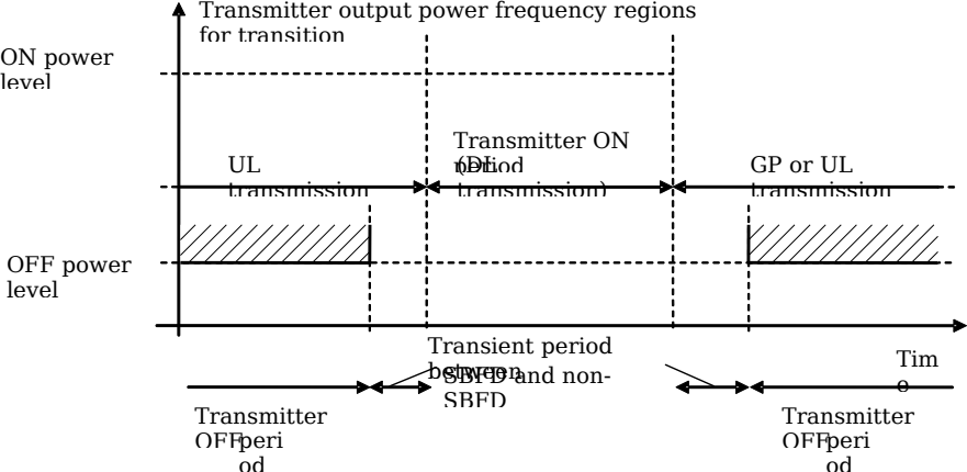 Figure 12.5.10.1-1: Example of relations between transmitter ON period, transmitter OFF period and transmitter transient period between SBFD and non-SBFD operation
The transmitter transient period for SBFD shall be measured in the transmission bandwidth configuration for SBFD DL subband, UL subband and guardband, depending on different cases as illustrated in table 12.5.10.1-1:
Table 12.5.10.1-1: Transmitter transient period between SBFD and non-SBFD operation
| | Frequency regions for transition | BS transmitter behavior during transition |
|--------------------------|----------------------------------------|-------------------------------------------------|
| SBFD symbol to DL symbol | SBFD UL subband and guardband(s) | BS transmitter OFF-to-ON |
| SBFD symbol to UL symbol | SBFD DL subband | BS transmitter ON-to-OFF |
| DL symbol to SBFD symbol | SBFD UL subband and guardband(s) | BS transmitter ON-to-OFF |
| UL symbol to SBFD symbol | SBFD DL subband | BS transmitter OFF-to-ON |This requirement shall be applied at each RIB supporting transmission in the operating band .
##### 12.5.10.2 Minimum requirement for BS type 1-OFor BS type 1-O , the OTA transmitter transient period between SBFD and non-SBFD operation shall be shorter than the values listed in the minimum requirement table 12.5.10.2-1.Table 12.5.10.2-1: Minimum requirement for the OTA transmitter transient period between SBFD and non-SBFD operation for BS type 1-O
| Transition | Transient period length (µs) |
|--------------|--------------------------------|
| OFF to ON | 10 |
| ON to OFF | 10 |
##### 12.5.10.3 Minimum requirement for BS type 2-OFor BS type 2-O , the OTA transmitter transient period between SBFD and non-SBFD operation shall be shorter than the values listed in the minimum requirement table 12.5.10.3-1.Table 12.5.10.3-1: Minimum requirement for the OTA transmitter transient period between SBFD and non-SBFD operation for BS type 2-O
| Transition | Transient period length (µs) |
|--------------|--------------------------------|
| OFF to ON | 3 |
| ON to OFF | 3 |
#### 12.5.11 OTA In-channel adjacent subband leakage for SBFD
##### 12.5.11.1 General
OTA In-channel adjacent subband leakage (ICASL) is the filtered mean power centred on the declared frequency region of UL subband configuration within NR carrier. The measured power is TRP.The requirement shall be applied per RIB during SBFD symbol .
##### 12.5.11.2 Minimum requirement for BS type 1-O
The ICASL shall be less than or equal to a basic limit defined in table 12.2.9.2-1 + X (where X = 9 dB).
##### 12.5.11.3 Minimum requirement for BS type 2-O
The ICASL shall be less than or equal to the value specified in table 12.5.11.3-1.Table 12.5.11.3-1: SBFD Base station ICASL absolute basic limit
| SBFD BS category / BS class | ICASL absolute basic limit |
|-------------------------------|---------------------------------|
| Wide Area BS | -13 dBm/MHz |
| Medium Range BS | -20 dBm/MHz |
| Local Area BS | -20 dBm/MHz |
Table 12.5.11.3-2: Filter parameters for the UL subband
| RAT | Filter on the assigned UL subband and corresponding filter bandwidth |
|--------|------------------------------------------------------------------------|
| NR | Square (the declared bandwidth of UL subband) |
### 12.6 Radiated receiver characteristics for SBFD-capable BS
#### 12.6.1 GeneralRadiated receiver characteristics are specified at RIB for BS type 1-H , BS type 1-O , or BS type 2-O , with full complement of transceivers configured for SBFD operation in normal operating condition.
#### 12.6.2 OTA sensitivity for SBFD
##### 12.6.2.1 BS type 1-H and BS type 1-O
###### 12.6.2.1.1 General
The general description of OTA sensitivity requirement as clause 10.2.1.1 shall also be applied for SBFD operation.
###### 12.6.2.1.2 Minimum requirementFor a received signal whose AoA of the incident wave is within the active sensitivity RoAoA of an OSDD, the error rate criterion as described in clause 7.2 shall be met when the level of the arriving signal is equal to the minimum EIS level with 0.7dB degradation allowed in the respective declared set of EIS level and UL subband bandwidth, in SBFD symbols with the transmitted signals in SBFD DL subband(s) present.
#### 12.6.3 OTA reference sensitivity level for SBFD
##### 12.6.3.1 General
The general description of OTA reference sensitivity requirement as clause 10.3.1 shall also be applied for SBFD operation.
##### 12.6.3.2 Minimum requirement for BS type 1-O
The OTA reference sensitivity requirement as specified in clause 10.3.2 with 0.7dB degradation allowed is applicable for SBFD operation in SBFD symbols with the transmitted signals in SBFD DL subband(s) present, in which the BS channel bandwidth specified in tables shall be replaced by SBFD UL subband bandwidth.
##### 12.6.3.3 Minimum requirement for BS type 2-O
The OTA reference sensitivity requirement as specified in clause 10.3.3 with 0.7dB degradation allowed is applicable for SBFD operation in SBFD symbols with the transmitted signals in SBFD DL subband(s) present, in which the BS channel bandwidth specified in tables shall be replaced by SBFD UL subband bandwidth.
#### 12.6.4 OTA dynamic range for SBFD
##### 12.6.4.1 General
The general description of OTA dynamic range requirement as clause 10.4.1 shall also be applied for SBFD operation.
##### 12.6.4.2 Minimum requirement for BS type 1-O
The same requirement as clause 10.4.2 is applicable to dynamic range requirement for SBFD operation, in which the BS channel bandwidth specified in tables shall be replaced by SBFD UL subband bandwidth.
#### 12.6.5 OTA in-band selectivity and blocking for SBFD
##### 12.6.5.1 OTA Adjacent Channel Selectivity for SBFD
###### 12.6.5.1.1 General
OTA Adjacent channel selectivity (ACS) is a measure of the receiver’s ability to receive an OTA wanted signal at its assigned channel frequency in the presence of an OTA adjacent channel signal with a specified centre frequency offset of the interfering signal to the band edge of a victim system.NOTE: SBFD UL subband is not configured adjacent to the Radio Bandwidth edge where cross link interference from adjacent channel may appear.
###### 12.6.5.1.2 Minimum requirement for BS type 1-OThe requirement shall apply at the RIB when the AoA of the incident wave of a received signal and the interfering signal are from the same direction and are within the minSENS RoAoA .The wanted and interfering signals apply to each supported polarization, under the assumption o f polarization match .
The throughput shall be ≥ 95% of the maximum throughput of the reference measurement channel.
For SBFD operation, the OTA wanted and the interfering signal are specified in table 12.6.5.1.2-1 for OTA ACS. The reference measurement channel for the OTA wanted signal is further specified in annex A.1. The characteristic of the interfering signal is further specified in annex D.The OTA ACS requirement is applicable outside the Base Station RF Bandwidth or Radio Bandwidth . The OTA interfering signal offset is defined relative to the Base station RF Bandwidth edges or Radio Bandwidth edges .Table 12.6.5.1.2-1: OTA ACS requirement for BS type 1-O for SBFD
| BS channel bandwidth of the lowest/highest carrier received (MHz) | Wanted signal mean power (dBm) (Note 1) | Interfering signal mean power (dBm) | Interfering signal centre frequency minimum offset from the lower/upper Base Station RF Bandwidth edge or sub-block edge inside a sub-block gap (MHz) | Type of interfering signal |
|--------------------------------------------------------------------------------------------------------------------------------------------------------------------------------------------------------------------------|--------------------------------------------|-------------------------------------------------------------------------------------------------------------|---------------------------------------------------------------------------------------------------------------------------------------------------------------------|----------------------------------------------|
| 20, 25, 30, 35, 40, 45, 50, 60, 70, 80, 90, 100 | EIS REFSENS + 6 dB | Wide Area BS: -28 - Δ OTAREFSENS Medium Range BS: -32 - Δ OTAREFSENS Local Area BS: -35 - Δ OTAREFSENS | ±10 | 20 MHz CP-OFDM NR signal 30 kHz SCS, 51 RBs |
| NOTE 1: EIS REFSENS is given in clause 12.6.3. NOTE 2: For lowest/highest carrier is configured in DU/UD SBFD operation, the interference only applies when DL subband is adjacent to Base Station RF Bandwidth edge. | | | | |
###### 12.6.5.1.3 Minimum requirement for BS type 2-OThe general minimum requirements are the same as those specified in clause 10.5.1.3, except for EIS REFSENS . The EIS REFSENS depends on the SBFD-capable BS class and the SBFD UL subband, and it is specified in clause 12.6.3.
##### 12.6.5.2 OTA in-band blocking for SBFD
###### 12.6.5.2.1 General
The OTA in-band blocking characteristics is a measure of the receiver’s ability to receive an OTA wanted signal at its assigned channel in the presence of an unwanted OTA interferer, which is an NR signal for general blocking or an NR signal with one RB for narrowband blocking.
NOTE 1: For FR1 WA BS, the in-band blocking requirements are derived based on the simulation assumption of 4GHz with 288 meters minimum distance coming from 100% grid shift between SBFD-capable BSs and neighbouring adjacent-channel TDD BSs. This NOTE shall not be interpreted as part of RF requirements.
NOTE 2: For FR1 MR BS, the in-band blocking requirements are derived based on the simulation assumption of 4GHz outdoor deployment with 167 meters minimum distance coming from 100% grid shift between SBFD-capable BSs and neighbouring adjacent-channel TDD BSs. This NOTE shall not be interpreted as part of RF requirements or in the context of indoor.NOTE 3: SBFD UL subband is not configured adjacent to the Radio Bandwidth edge where cross link interference from adjacent channel may appear.
NOTE 4: For FR2-1 WA BS, the in-band blocking requirements are derived based on the simulation assumption of 30GHz with 115 meters minimum distance coming from 100% grid shift between SBFD-capable BSs and neighbouring adjacent-channel TDD BSs. This NOTE shall not be interpreted as part of RF requirements.
###### 12.6.5.2.2 Minimum requirement for BS type 1-O
The requirement shall apply at the RIB when the AoA of the incident wave of a received signal and the interfering signal are from the same direction, and:- when the wanted signal is based on EIS REFSENS : the AoA of the incident wave of a received signal and the interfering signal are within the OTA REFSENS RoAoA.- when the wanted signal is based on EIS minSENS : the AoA of the incident wave of a received signal and the interfering signal are within the minSENS RoAoA .The wanted and interfering signals apply to each supported polarization, under the assumption of polarization match .
The throughput shall be ≥ 95% of the maximum throughput of the reference measurement channel, with OTA wanted and OTA interfering signal specified in tables 12.6.5.2.2-1 for general OTA blocking requirements. The reference measurement channel for the OTA wanted signal is further specified in annex A.1. The characteristics of the interfering signal is further specified in annex D.The OTA in-band blocking requirements apply outside the Base Station RF Bandwidth or Radio Bandwidth . The interfering signal offset is defined relative to the Base Station RF Bandwidth edges or Radio Bandwidth edges.Table 12.6.5.2.2-1: General OTA blocking requirement for BS type 1-O
| BS channel bandwidth of the lowest/highest carrier received (MHz) | Wanted signal mean power (dBm) (Note 1) | Interfering signal mean power (dBm) | Interfering signal centre frequency minimum offset from the lower/upper Base Station RF Bandwidth edge or sub-block edge inside a sub-block gap (MHz) | Type of interfering signal |
|--------------------------------------------------------------------------------------------------------------------------------------------------------------------------------------------------------------------------------|--------------------------------------------|-------------------------------------------------------------------------------------------------------------|---------------------------------------------------------------------------------------------------------------------------------------------------------------------|----------------------------------------------|
| 20, 25, 30, 35, 40, 45, 50, 60, 70, 80, 90, 100 | EIS REFSENS + 6 dB | Wide Area BS: -25 - Δ OTAREFSENS Medium Range BS: -32 - Δ OTAREFSENS Local Area BS: -35 - Δ OTAREFSENS | ±30 | 20 MHz CP-OFDM NR signal 30 kHz SCS, 51 RBs |
| 20, 25, 30, 35, 40, 45, 50, 60, 70, 80, 90, 100 | EIS minSENS + 6 dB | Wide Area BS: -25 - Δ minSENS Medium Range BS: -32 - Δ minSENS Local Area BS: -35 - Δ minSENS | ±30 | |
| NOTE 1: EIS REFSENS is given in clause 12.6.3. NOTE 2: For lowest/highest carrier which is configured in DU/UD SBFD operation, the interference only applies when DL subband is adjacent to Base Station RF Bandwidth edge. | | | | |
###### 12.6.5.2.3 Minimum requirement for BS type 2-OThe requirement shall apply at the RIB when the AoA of the incident wave of a received signal and the interfering signal are from the same direction and are within the *OTA REFSENS RoAoA.*The wanted and interfering signals apply to each supported polarization, under the assumption o f polarization match .
The throughput shall be ≥ 95% of the maximum throughput of the reference measurement channel.For BS type 2-O , the OTA wanted and OTA interfering signals are provided at RIB using the parameters in table 12.6.5.2.2-1 for general OTA blocking requirements. The reference measurement channel for the wanted signal is further specified in annex A.1. The characteristics of the interfering signal is further specified in annex D.The OTA blocking requirements are applicable outside the Base Station RF Bandwidth . The interfering signal offset is defined relative to the Base Station RF Bandwidth edges.Table 12.6.5.2.3-1: General OTA blocking requirement for BS type 2-O
| Frequency Range | BS channel bandwidth of the lowest/highest carrier received (MHz) | OTA wanted signal mean power (dBm) | OTA interfering signal mean power (dBm) | OTA interfering signal centre frequency offset from the lower/upper Base Station RF Bandwidth edge (MHz) | Type of OTA interfering signal |
|--------------------------------------------------------------------------------------------------------------------------------------------------------------------------------------------------------------------------------------------------------|---------------------------------------------------------------------|--------------------------------------|-------------------------------------------|-------------------------------------------------------------------------------------------------------------|--------------------------------------------------|
| FR2-1 | 100, 200, 400 | EIS REFSENS + 6 dB | EIS REFSENS_50M + 37 + Δ FR2_REFSENS | ±75 | 50 MHz DFT-s-OFDM NR signal, 60 kHz SCS, 64 RBs |
| NOTE 1: EIS REFSENS and EIS REFSENS_50M are given in clause 12.6.3. NOTE 2: For lowest/highest carrier which is configured in DU/UD SBFD operation, the interference only applies when DL subband is adjacent to Base Station RF Bandwidth edge. | | | | | |
#### 12.6.6 OTA out-of-band blocking for SBFD
##### 12.6.6.1 General
The general requirement of OTA out-of-band blocking for SBFD-capable BS is the same as general requirement specified in clause 10.6.1.
##### 12.6.6.2 Minimum requirement for BS type 1-O
###### 12.6.6.2.1 General minimum requirementThe general minimum requirements are the same as those specified in clause 10.6.2.1, except for EIS minSENS . The EIS minSENS depends on the SBFD-capable BS class and the SBFD UL subband, and it is specified in clause 12.6.2.
###### 12.6.6.2.2 Co-location minimum requirementThe co-location minimum requirements are the same as those specified in clause 10.6.2.2, except for EIS minSENS . The EIS minSENS depends on the SBFD-capable BS class and the SBFD UL subband, and it is specified in clause 12.6.2.
##### 12.6.6.3 Minimum requirement for BS type 2-O
###### 12.6.6.3.1 General minimum requirementThe general minimum requirements are the same as those specified in clause 10.6.3.1, except for EIS REFSENS . The EIS REFSENS depends on the SBFD-capable BS class and the SBFD UL subband, and it is specified in clause 12.6.3.
#### 12.6.7 OTA receiver spurious emissions for SBFD
##### 12.6.7.1 General
The general description given in Clause 10.7.1 shall be applied.
##### 12.6.7.2 Minimum requirement for BS type 1-O
The same requirements as specified in Clause 10.7.2 shall be applied.
##### 12.6.7.3 Minimum requirement for BS type 2-O
The same requirements as specified in Clause 10.7.3 shall be applied.
#### 12.6.8 OTA in-channel selectivity for SBFDThe same requirements as specified in clause 10.9 shall be applied to SBFD-capable BS type 1-O and BS type 2-O during SBFD symbol , except for the note in table 10.9.2-1, table 10.9.2-1a, table 10.9.2-2, table 10.9.2-2a, table 10.9.2-3 and table 10.9.2-3a, which shall be adjusted to: Wanted and interfering signal are placed adjacently around F C,SBFD,UL . The aggregated wanted and interferer signal shall be centred in the SBFD UL subband bandwidth of the wanted signal. For DU/UD pattern, place the wanted signal closer to the DL subband.
#### 12.6.9 OTA in-channel adjacent subband blocking for SBFD
##### 12.6.9.1 General
OTA in-channel adjacent subband blocking requirement is a measure of the receiver’s ability to receive an OTA wanted signal at its assigned channel frequency in the presence of an OTA interfering signal from other sector(s) and/or site(s) within the same operator’s network, which is an NR signal.
##### 12.6.9.2 Minimum requirement for BS type 1-O
The requirement shall apply at the RIB when the AoA of the incident wave of a received signal and the interfering signal are from the same direction, and:- when the wanted signal is based on EIS REFSENS : the AoA of the incident wave of a received signal and the interfering signal are within the OTA REFSENS RoAoA.- when the wanted signal is based on EIS minSENS : the AoA of the incident wave of a received signal and the interfering signal are within the minSENS RoAoA .The wanted and interfering signals apply to each supported polarization, under the assumption o f polarization match .The throughput shall be ≥ 95% of the maximum throughput of the reference measurement channel, with an OTA wanted signal and OTA interfering signal(s) using the parameters specified in table 12.6.9.2-1. The reference measurement channel for the wanted signal is identified in clause 10.3.2 for each SBFD UL subband bandwidth and are further specified in annex A.1. The characteristic of the interfering signal(s) is further specified in annex D.The OTA in-channel adjacent subband blocking requirement shall apply to SBFD UL subband bandwidth . The interfering signal(s) shall be positioned at the centre frequency of the SBFD DL subband bandwidth(s) .Table 12.6.9.2-1: In-channel adjacent subband blocking requirement for BS type 1-O
| SBFD UL subband bandwidth (MHz) | Wanted signal mean power (dBm) (NOTE 1) | Interfering signal mean power (dBm) (NOTE 5) | SBFD UD/UD or DUD case | Interfering signal centre frequency/frequencies | Type of interfering signal(s) (NOTE 2, 3, 4) |
|--------------------------------------------------------------------------------------------------------------------------------------------------------------------------------------------------------------------------------------------------------------------------------------------------------------------------------------------------------------------------------------------------------------------------------------------------------------------------------------------------------------------------------------------------------------------------------------------------------------------------------------------------------------------------------------------------------------------------------------------------------------------------------------------------------------------------------------------------------------------------------------------------------------------------------------------------------------------------------------------------------------------------------------------------------------------------------------------------------------------------------------------------------------------------------------------------------------------------------------------------------------------------------------------------------------------------------------------------------------------------------------------------|--------------------------------------------|-------------------------------------------------------------------------------------------------------------|--------------------------|---------------------------------------------------|--------------------------------------------------------------------------|
| 10, 15, 20, 25, 30, 35, 40, 45, 50, 60, 70, 80, 90 | EIS REFSENS + 6 dB | Wide Area BS: -28 - Δ OTAREFSENS Medium Range BS: -32 - Δ OTAREFSENS Local Area BS: -34 - Δ OTAREFSENS | DU or UD | F C,SBFD,DL | CP-OFDM NR signal 30 kHz SCS, BW = X (in the unit of RB) |
| 10, 15, 20, 25, 30, 35, 40, 45, 50, 60, 70, 80, 90 | | | DUD | F C,SBFD,DL,1 F C,SBFD,DL,2 | CP-OFDM NR signal 30 kHz SCS, BW1 = X1 and BW2 = X2 (in the unit of RB) |
| 10, 15, 20, 25, 30, 35, 40, 45, 50, 60, 70, 80, 90 | EIS minSENS + 6 dB | Wide Area BS: -28 - Δ minSENS Medium Range BS: -32 - Δ minSENS Local Area BS: -34 - Δ minSENS | DU or UD | F C,SBFD,DL | CP-OFDM NR signal 30 kHz SCS, BW = X (in the unit of RB) |
| 10, 15, 20, 25, 30, 35, 40, 45, 50, 60, 70, 80, 90 | | | DUD | F C,SBFD,DL,1 F C,SBFD,DL,2 | CP-OFDM NR signal 30 kHz SCS, BW1 = X1 and BW2 = X2 (in the unit of RB) |
| NOTE 1: P REFSENS depends on the SBFD UL subband bandwidth as specified in clause 12.3.2. NOTE 2: For DU or UD case, interfering signal is placed at F C,SBFD,DL . For DUD case, two interfering signals are placed at F C,SBFD,DL,1 and F C,SBFD,DL,2 , respectively. OTA interfering signal mean power is the total power of the two interfering signals and the two interfering signals have the same power density. NOTE 3: For DU or UD case, X is the largest transmission bandwidth configuration as specified in table 5.3.2-1 that is not larger than N RB, SBFD, DL . For DUD case, X1 is the largest transmission bandwidth configuration as specified in table 5.3.2-1 that is not larger than N RB, SBFD, DL,1 and X2 is the largest transmission bandwidth configuration as specified in table 5.3.2-1 that is not larger than N RB, SBFD, DL,2 . NOTE 4: In case the SBFD BS is configured with intra-band carrier aggregation, the set of interfering signals consists of the interfering signal(s) in this table and the signals from other intra-band contiguous carrier(s) operated in non-SBFD operation. The power spectral density of each interfering signal is set to be the same level. NOTE 5: For FR1 WA BS, in-channel adjacent subband blocking requirement assumes 80 dBc coupling loss between interfering BS transmitter and SBFD BS receiver. | | | | | |
##### 12.6.9.3 Minimum requirement for BS type 2-OThe requirement shall apply at the RIB when the AoA of the incident wave of a received signal and the interfering signal are from the same direction and are within the *OTA REFSENS RoAoA.*The wanted and interfering signals apply to each supported polarization, under the assumption o f polarization match .
The throughput shall be ≥ 95% of the maximum throughput of the reference measurement channel, with an OTA wanted signal and OTA interfering signal(s) using the parameters specified in table 12.6.9.3-1. The reference measurement channel for the wanted signal is further specified in annex A.1. The characteristic of the interfering signal(s) is further specified in annex D.The OTA in-channel adjacent subband blocking requirement shall apply to SBFD UL subband bandwidth . The interfering signal(s) shall be positioned at the centre frequency of the SBFD DL subband bandwidth(s) .Table 12.6.9.3-1: In-channel adjacent subband blocking requirement for BS type 2-O
| Frequency Range | SBFD UL subband bandwidth (MHz) | OTA wanted signal mean power (dBm) (NOTE 1) | OTA interfering signal mean power (dBm) (NOTE 5) | SBFD UD/UD or DUD case | Interfering signal centre frequency/frequencies | Type of interfering signal(s) (NOTE 2, 3, 4) |
|--------------------------------------------------------------------------------------------------------------------------------------------------------------------------------------------------------------------------------------------------------------------------------------------------------------------------------------------------------------------------------------------------------------------------------------------------------------------------------------------------------------------------------------------------------------------------------------------------------------------------------------------------------------------------------------------------------------------------------------------------------------------------------------------------------------------------------------------------------------------------------------------------------------------------------------------------------------------------------------------------------------------------------------------------------------------------------------------------------------------------------------------------------------------------------------------------------------------------------------------------------------------------------------------------------------------------------------------------------------------------------------------------------|-----------------------------------|-----------------------------------------------|---------------------------------------------------------|--------------------------|---------------------------------------------------|--------------------------------------------------------------------------|
| FR2-1 | 50, 100, 200 | EIS REFSENS + 6 dB | Wide Area BS: EIS REFSENS_50M + 34 + Δ FR2_REFSENS | DU or UD | F C,SBFD,DL | CP-OFDM NR signal 60 kHz SCS, BW = X (in the unit of RB) |
| FR2-1 | 50, 100, 200 | | | DUD | F C,SBFD,DL,1 F C,SBFD,DL,2 | CP-OFDM NR signal 60 kHz SCS, BW1 = X1 and BW2 = X2 (in the unit of RB) |
| NOTE 1: EIS REFSENS depends on the SBFD BS UL subband bandwidth as specified in clause 12.6.3. NOTE 2: For DU or UD case, interfering signal is placed at F C,SBFD,DL . For DUD case, two interfering signals are placed at F C,SBFD,DL,1 and F C,SBFD,DL,2 , respectively, OTA interfering signal mean power is the total power of the two interfering signals and the two interfering signals have the same power density NOTE 3: For DU or UD case, X is the largest transmission bandwidth configuration as specified in table 5.3.2-2 that is not larger than N RB, SBFD, DL . For DUD case, X1 is the largest transmission bandwidth configuration as specified in table 5.3.2-2 that is not larger than N RB, SBFD, DL,1 and X2 is the largest transmission bandwidth configuration as specified in table 5.3.2-2 that is not larger than N RB, SBFD, DL,2 . NOTE 4: In case the SBFD BS is configured with intra-band carrier aggregation, the set of interfering signals consists of the interfering signal(s) in this table and the signals from other intra-band contiguous carrier(s) operated in non-SBFD operation. The power spectral density of each interfering signal is set to be the same level. NOTE 5: For FR2-1 WA BS, in-channel adjacent subband blocking requirement assumes 87 dBc coupling loss between interfering BS transmitter and SBFD BS receiver. | | | | | | |
### 12.7 Radiated performance requirements for SBFD-capable BS
#### 12.7.1 General
##### 12.7.1.1 Scope and definitionsRadiated performance requirements specify the ability of the SBFD-capable BS type 1-O or BS type 2-O to correctly demodulate radiated signals in various conditions and configurations. Radiated performance requirements are specified at the RIB.
Radiated performance requirements for the BS are specified for the fixed reference channels defined in annex A and the propagation conditions in annex G. The requirements only apply to those FRCs that are supported by the BS.The radiated performance requirements for SBFD-capable BS type 1-O and for the SBFD-capable BS type 2-O are limited to two OTA demodulation branches as described in clause 12.7.1.2. Conformance requirements can only be tested for 1 or 2 demodulation branches depending on the number of polarizations supported by the BS, with the required SNR applied separately per polarization.NOTE 1: The BS can support more than 2 demodulation branches , however OTA conformance testing can only be performed for 1 or 2 demodulation branches .
Unless stated otherwise, radiated performance requirements apply for a single carrier only. Radiated performance requirements for a BS supporting CA are defined in terms of single carrier requirements.
In tests performed with signal generators a synchronization signal may be provided from the BS to the signal generator, to enable correct timing of the wanted signal.Whenever the “RX antennas” term is used for the radiated performance requirements description, it shall refer to the demodulation branches (i.e. not physical antennas of the antenna array).
The SNR used in this clause is specified based on a single carrier and defined as:
SNR = S / N
Where:
S is the total signal energy in a slot on a RIB.N is the noise energy in a bandwidth corresponding to the transmission bandwidth over the duration where signal energy exists on a RIB.
##### 12.7.1.2 OTA demodulation branchesRadiated performance requirements are only specified for up to 2 demodulation branches .If the SBFD-capable BS type 1-O , or the SBFD-capable BS type 2-O uses polarization diversity and has the ability to maintain isolation between the signals for each of the demodulation branches , then radiated performance requirements can be tested for up to two demodulation branches (i.e., 1RX or 2RX test setups). When tested for two demodulation branches , each demodulation branch maps to one polarization.If the SBFD-capable BS type 1-O , or the SBFD-capable BS type 2-O does not use polarization diversity then radiated performance requirements can only be tested for a single demodulation branch (i.e., 1RX test setup).
##### 12.7.1.3 Void
#### 12.7.2 Performance requirements for PUSCH
##### 12.7.2.1 Requirements for BS type 1-O
###### 12.7.2.1.1 Requirements for PUSCH with transform precoding disabled
Apply the requirements defined in clause 12.4.2.1 for 2Rx.
###### 12.7.2.1.2 Requirements for PUSCH with transform precoding enabled
Apply the requirements defined in clause 12.4.2.2 for 2Rx.
###### 12.7.2.1.3 Requirements for UCI multiplexed on PUSCH
Apply the requirements defined in clause 12.4.2.3 for 2Rx.
###### 12.7.2.1.4 Enhanced performance requirements for PUSCH with synchronous interference
Apply the requirements defined in clause 12.4.2.4 for 2Rx.
###### 12.7.2.1.5 Requirements for PUSCH with UL resource muting
Apply the requirements defined in clause 12.4.2.5 for 2Rx.
##### 12.7.2.2 Requirements for BS type 2-O
###### 12.7.2.2.1 Requirements for PUSCH with transform precoding disabledThe same general description and requirements as clause 11.2.2.1 is appliable to requirements for PUSCH with transform precoding disabled, where the PUSCH received at at the RIB for SBFD-capable BS type 2-O inside the received SBFD UL subband for SBFD operation, and the BS channel bandwidth specified in the tables shall be replaced by SBFD UL subband bandwidth.
###### 12.7.2.2.2 Requirements for PUSCH with transform precoding enabledThe same general description and requirements as clause 11.2.2.2 is appliable to requirements for PUSCH with transform precoding enabled, where the PUSCH received at at the RIB for SBFD-capable BS type 2-O inside the received SBFD UL subband for SBFD operation, and the BS channel bandwidth specified in the tables shall be replaced by SBFD UL subband bandwidth.
###### 12.7.2.2.3 Requirements for UCI multiplexed on PUSCHThe same general description and requirements as clause 11.2.2.3 is appliable to requirements for UCI multiplexed on PUSCH, where the UCI multiplexed on PUSCH received at at the RIB for SBFD-capable BS type 2-O inside the received SBFD UL subband for SBFD operation, and the BS channel bandwidth specified in the tables shall be replaced by SBFD UL subband bandwidth.
#### 12.7.3 Performance requirements for PUCCH
##### 12.7.3.1 Requirements for BS type 1-O
###### 12.7.3.1.1 DTX to ACK probability
Apply the requirements defined in clause 12.4.3.1
###### 12.7.3.1.2 Performance requirements for PUCCH format 0
Apply the requirements defined in clause 12.4.3.2 for 2 Rx.
###### 12.7.3.1.3 Performance requirements for PUCCH format 1
Apply the requirements defined in sub-clause 12.4.3.3 for 2Rx.
###### 12.7.3.1.4 Performance requirements for PUCCH format 2
Apply the requirements defined in clause 12.4.3.4 for 2Rx.
###### 12.7.3.1.5 Performance requirements for PUCCH format 3
Apply the requirements defined in clause 12.4.3.5 for 2Rx.
###### 12.7.3.1.6 Performance requirements for PUCCH format 4
Apply the requirements defined in clause 12.4.3.6 for 2Rx.
###### 12.7.3.1.7 Performance requirements for multi-slot PUCCH
Apply the requirements defined in clause 12.4.3.7 for 2Rx.
##### 12.7.3.2 Requirements for BS type 2-O
###### 12.7.3.2.1 DTX to ACK probability
Apply the requirements defined in clause 11.3.2.1.
###### 12.7.3.2.2 Performance requirements for PUCCH format 0.The same general description and requirements as clause 11.3.2.2 is appliable to requirements for PUCCH format 0, where the PUCCH format 0 received at at the RIB for SBFD-capable BS type 2-O inside the received SBFD UL subband for SBFD operation, and the BS channel bandwidth specified in the tables shall be replaced by SBFD UL subband bandwidth.
###### 12.7.3.2.3 Performance requirements for PUCCH format 1.The same general description and requirements as clause 11.3.2.3 is appliable to requirements for PUCCH format 1, where the PUCCH format 1 received at at the RIB for SBFD-capable BS type 2-O inside the received SBFD UL subband for SBFD operation, and the BS channel bandwidth specified in the tables shall be replaced by SBFD UL subband bandwidth.
###### 12.7.3.2.4 Performance requirements for PUCCH format 2The same general description and requirements as clause 11.3.2.4 is appliable to requirements for PUCCH format 2, where the PUCCH format 2 received at at the RIB for SBFD-capable BS type 2-O inside the received SBFD UL subband for SBFD operation, and the BS channel bandwidth specified in the tables shall be replaced by SBFD UL subband bandwidth.
###### 12.7.3.2.5 Performance requirements for PUCCH format 3The same general description and requirements as clause 11.3.2.5 is appliable to requirements for PUCCH format 3, where the PUCCH format 3 received at at the RIB for SBFD-capable BS type 2-O inside the received SBFD UL subband for SBFD operation, and the BS channel bandwidth specified in the tables shall be replaced by SBFD UL subband bandwidth.
###### 12.7.3.2.6 Performance requirements for PUCCH format 4The same general description and requirements as clause 11.3.2.6 is appliable to requirements for PUCCH format 4, where the PUCCH format 4 received at at the RIB for SBFD-capable BS type 2-O inside the received SBFD UL subband for SBFD operation, and the BS channel bandwidth specified in the tables shall be replaced by SBFD UL subband bandwidth.
#### 12.7.4 Performance requirements for PRACH
##### 12.7.4.1 Requirements for BS type 1-O
###### 12.7.4.1.1 PRACH False alarm probability
Apply the requirements defined in clause 12.4.4.1 for 2Rx.
###### 12.7.4.1.2 PRACH detection requirements
Apply the requirements defined in clause 12.4.4.2 for 2Rx.
##### 12.7.4.2 Requirements for BS type 2-O
###### 12.7.4.2.1 PRACH False alarm probabilityThe same general description and requirements as clause 11.4.2.1 is appliable to requirements for PRACH, where the PRACH received at at the RIB for SBFD-capable BS type 2-O inside the received SBFD UL subband for SBFD operation, and the BS channel bandwidth specified in the tables shall be replaced by SBFD UL subband bandwidth.
###### 12.7.4.2.2 PRACH detection requirementsThe same general description and requirements as clause 11.4.2.2.2 is appliable to requirements for PRACH, where the PRACH received at at the RIB for SBFD-capable BS type 2-O inside the received SBFD UL subband for SBFD operation, and the BS channel bandwidth specified in the tables shall be replaced by SBFD UL subband bandwidth.
######### Annex A (normative):
Reference measurement channels
Figure 12.5.10.1-1: Example of relations between transmitter ON period, transmitter OFF period and transmitter transient period between SBFD and non-SBFD operation
The transmitter transient period for SBFD shall be measured in the transmission bandwidth configuration for SBFD DL subband, UL subband and guardband, depending on different cases as illustrated in table 12.5.10.1-1:
Table 12.5.10.1-1: Transmitter transient period between SBFD and non-SBFD operation
| | Frequency regions for transition | BS transmitter behavior during transition |
|--------------------------|----------------------------------------|-------------------------------------------------|
| SBFD symbol to DL symbol | SBFD UL subband and guardband(s) | BS transmitter OFF-to-ON |
| SBFD symbol to UL symbol | SBFD DL subband | BS transmitter ON-to-OFF |
| DL symbol to SBFD symbol | SBFD UL subband and guardband(s) | BS transmitter ON-to-OFF |
| UL symbol to SBFD symbol | SBFD DL subband | BS transmitter OFF-to-ON |This requirement shall be applied at each RIB supporting transmission in the operating band .
##### 12.5.10.2 Minimum requirement for BS type 1-OFor BS type 1-O , the OTA transmitter transient period between SBFD and non-SBFD operation shall be shorter than the values listed in the minimum requirement table 12.5.10.2-1.Table 12.5.10.2-1: Minimum requirement for the OTA transmitter transient period between SBFD and non-SBFD operation for BS type 1-O
| Transition | Transient period length (µs) |
|--------------|--------------------------------|
| OFF to ON | 10 |
| ON to OFF | 10 |
##### 12.5.10.3 Minimum requirement for BS type 2-OFor BS type 2-O , the OTA transmitter transient period between SBFD and non-SBFD operation shall be shorter than the values listed in the minimum requirement table 12.5.10.3-1.Table 12.5.10.3-1: Minimum requirement for the OTA transmitter transient period between SBFD and non-SBFD operation for BS type 2-O
| Transition | Transient period length (µs) |
|--------------|--------------------------------|
| OFF to ON | 3 |
| ON to OFF | 3 |
#### 12.5.11 OTA In-channel adjacent subband leakage for SBFD
##### 12.5.11.1 General
OTA In-channel adjacent subband leakage (ICASL) is the filtered mean power centred on the declared frequency region of UL subband configuration within NR carrier. The measured power is TRP.The requirement shall be applied per RIB during SBFD symbol .
##### 12.5.11.2 Minimum requirement for BS type 1-O
The ICASL shall be less than or equal to a basic limit defined in table 12.2.9.2-1 + X (where X = 9 dB).
##### 12.5.11.3 Minimum requirement for BS type 2-O
The ICASL shall be less than or equal to the value specified in table 12.5.11.3-1.Table 12.5.11.3-1: SBFD Base station ICASL absolute basic limit
| SBFD BS category / BS class | ICASL absolute basic limit |
|-------------------------------|---------------------------------|
| Wide Area BS | -13 dBm/MHz |
| Medium Range BS | -20 dBm/MHz |
| Local Area BS | -20 dBm/MHz |
Table 12.5.11.3-2: Filter parameters for the UL subband
| RAT | Filter on the assigned UL subband and corresponding filter bandwidth |
|--------|------------------------------------------------------------------------|
| NR | Square (the declared bandwidth of UL subband) |
### 12.6 Radiated receiver characteristics for SBFD-capable BS
#### 12.6.1 GeneralRadiated receiver characteristics are specified at RIB for BS type 1-H , BS type 1-O , or BS type 2-O , with full complement of transceivers configured for SBFD operation in normal operating condition.
#### 12.6.2 OTA sensitivity for SBFD
##### 12.6.2.1 BS type 1-H and BS type 1-O
###### 12.6.2.1.1 General
The general description of OTA sensitivity requirement as clause 10.2.1.1 shall also be applied for SBFD operation.
###### 12.6.2.1.2 Minimum requirementFor a received signal whose AoA of the incident wave is within the active sensitivity RoAoA of an OSDD, the error rate criterion as described in clause 7.2 shall be met when the level of the arriving signal is equal to the minimum EIS level with 0.7dB degradation allowed in the respective declared set of EIS level and UL subband bandwidth, in SBFD symbols with the transmitted signals in SBFD DL subband(s) present.
#### 12.6.3 OTA reference sensitivity level for SBFD
##### 12.6.3.1 General
The general description of OTA reference sensitivity requirement as clause 10.3.1 shall also be applied for SBFD operation.
##### 12.6.3.2 Minimum requirement for BS type 1-O
The OTA reference sensitivity requirement as specified in clause 10.3.2 with 0.7dB degradation allowed is applicable for SBFD operation in SBFD symbols with the transmitted signals in SBFD DL subband(s) present, in which the BS channel bandwidth specified in tables shall be replaced by SBFD UL subband bandwidth.
##### 12.6.3.3 Minimum requirement for BS type 2-O
The OTA reference sensitivity requirement as specified in clause 10.3.3 with 0.7dB degradation allowed is applicable for SBFD operation in SBFD symbols with the transmitted signals in SBFD DL subband(s) present, in which the BS channel bandwidth specified in tables shall be replaced by SBFD UL subband bandwidth.
#### 12.6.4 OTA dynamic range for SBFD
##### 12.6.4.1 General
The general description of OTA dynamic range requirement as clause 10.4.1 shall also be applied for SBFD operation.
##### 12.6.4.2 Minimum requirement for BS type 1-O
The same requirement as clause 10.4.2 is applicable to dynamic range requirement for SBFD operation, in which the BS channel bandwidth specified in tables shall be replaced by SBFD UL subband bandwidth.
#### 12.6.5 OTA in-band selectivity and blocking for SBFD
##### 12.6.5.1 OTA Adjacent Channel Selectivity for SBFD
###### 12.6.5.1.1 General
OTA Adjacent channel selectivity (ACS) is a measure of the receiver’s ability to receive an OTA wanted signal at its assigned channel frequency in the presence of an OTA adjacent channel signal with a specified centre frequency offset of the interfering signal to the band edge of a victim system.NOTE: SBFD UL subband is not configured adjacent to the Radio Bandwidth edge where cross link interference from adjacent channel may appear.
###### 12.6.5.1.2 Minimum requirement for BS type 1-OThe requirement shall apply at the RIB when the AoA of the incident wave of a received signal and the interfering signal are from the same direction and are within the minSENS RoAoA .The wanted and interfering signals apply to each supported polarization, under the assumption o f polarization match .
The throughput shall be ≥ 95% of the maximum throughput of the reference measurement channel.
For SBFD operation, the OTA wanted and the interfering signal are specified in table 12.6.5.1.2-1 for OTA ACS. The reference measurement channel for the OTA wanted signal is further specified in annex A.1. The characteristic of the interfering signal is further specified in annex D.The OTA ACS requirement is applicable outside the Base Station RF Bandwidth or Radio Bandwidth . The OTA interfering signal offset is defined relative to the Base station RF Bandwidth edges or Radio Bandwidth edges .Table 12.6.5.1.2-1: OTA ACS requirement for BS type 1-O for SBFD
| BS channel bandwidth of the lowest/highest carrier received (MHz) | Wanted signal mean power (dBm) (Note 1) | Interfering signal mean power (dBm) | Interfering signal centre frequency minimum offset from the lower/upper Base Station RF Bandwidth edge or sub-block edge inside a sub-block gap (MHz) | Type of interfering signal |
|--------------------------------------------------------------------------------------------------------------------------------------------------------------------------------------------------------------------------|--------------------------------------------|-------------------------------------------------------------------------------------------------------------|---------------------------------------------------------------------------------------------------------------------------------------------------------------------|----------------------------------------------|
| 20, 25, 30, 35, 40, 45, 50, 60, 70, 80, 90, 100 | EIS REFSENS + 6 dB | Wide Area BS: -28 - Δ OTAREFSENS Medium Range BS: -32 - Δ OTAREFSENS Local Area BS: -35 - Δ OTAREFSENS | ±10 | 20 MHz CP-OFDM NR signal 30 kHz SCS, 51 RBs |
| NOTE 1: EIS REFSENS is given in clause 12.6.3. NOTE 2: For lowest/highest carrier is configured in DU/UD SBFD operation, the interference only applies when DL subband is adjacent to Base Station RF Bandwidth edge. | | | | |
###### 12.6.5.1.3 Minimum requirement for BS type 2-OThe general minimum requirements are the same as those specified in clause 10.5.1.3, except for EIS REFSENS . The EIS REFSENS depends on the SBFD-capable BS class and the SBFD UL subband, and it is specified in clause 12.6.3.
##### 12.6.5.2 OTA in-band blocking for SBFD
###### 12.6.5.2.1 General
The OTA in-band blocking characteristics is a measure of the receiver’s ability to receive an OTA wanted signal at its assigned channel in the presence of an unwanted OTA interferer, which is an NR signal for general blocking or an NR signal with one RB for narrowband blocking.
NOTE 1: For FR1 WA BS, the in-band blocking requirements are derived based on the simulation assumption of 4GHz with 288 meters minimum distance coming from 100% grid shift between SBFD-capable BSs and neighbouring adjacent-channel TDD BSs. This NOTE shall not be interpreted as part of RF requirements.
NOTE 2: For FR1 MR BS, the in-band blocking requirements are derived based on the simulation assumption of 4GHz outdoor deployment with 167 meters minimum distance coming from 100% grid shift between SBFD-capable BSs and neighbouring adjacent-channel TDD BSs. This NOTE shall not be interpreted as part of RF requirements or in the context of indoor.NOTE 3: SBFD UL subband is not configured adjacent to the Radio Bandwidth edge where cross link interference from adjacent channel may appear.
NOTE 4: For FR2-1 WA BS, the in-band blocking requirements are derived based on the simulation assumption of 30GHz with 115 meters minimum distance coming from 100% grid shift between SBFD-capable BSs and neighbouring adjacent-channel TDD BSs. This NOTE shall not be interpreted as part of RF requirements.
###### 12.6.5.2.2 Minimum requirement for BS type 1-O
The requirement shall apply at the RIB when the AoA of the incident wave of a received signal and the interfering signal are from the same direction, and:- when the wanted signal is based on EIS REFSENS : the AoA of the incident wave of a received signal and the interfering signal are within the OTA REFSENS RoAoA.- when the wanted signal is based on EIS minSENS : the AoA of the incident wave of a received signal and the interfering signal are within the minSENS RoAoA .The wanted and interfering signals apply to each supported polarization, under the assumption of polarization match .
The throughput shall be ≥ 95% of the maximum throughput of the reference measurement channel, with OTA wanted and OTA interfering signal specified in tables 12.6.5.2.2-1 for general OTA blocking requirements. The reference measurement channel for the OTA wanted signal is further specified in annex A.1. The characteristics of the interfering signal is further specified in annex D.The OTA in-band blocking requirements apply outside the Base Station RF Bandwidth or Radio Bandwidth . The interfering signal offset is defined relative to the Base Station RF Bandwidth edges or Radio Bandwidth edges.Table 12.6.5.2.2-1: General OTA blocking requirement for BS type 1-O
| BS channel bandwidth of the lowest/highest carrier received (MHz) | Wanted signal mean power (dBm) (Note 1) | Interfering signal mean power (dBm) | Interfering signal centre frequency minimum offset from the lower/upper Base Station RF Bandwidth edge or sub-block edge inside a sub-block gap (MHz) | Type of interfering signal |
|--------------------------------------------------------------------------------------------------------------------------------------------------------------------------------------------------------------------------------|--------------------------------------------|-------------------------------------------------------------------------------------------------------------|---------------------------------------------------------------------------------------------------------------------------------------------------------------------|----------------------------------------------|
| 20, 25, 30, 35, 40, 45, 50, 60, 70, 80, 90, 100 | EIS REFSENS + 6 dB | Wide Area BS: -25 - Δ OTAREFSENS Medium Range BS: -32 - Δ OTAREFSENS Local Area BS: -35 - Δ OTAREFSENS | ±30 | 20 MHz CP-OFDM NR signal 30 kHz SCS, 51 RBs |
| 20, 25, 30, 35, 40, 45, 50, 60, 70, 80, 90, 100 | EIS minSENS + 6 dB | Wide Area BS: -25 - Δ minSENS Medium Range BS: -32 - Δ minSENS Local Area BS: -35 - Δ minSENS | ±30 | |
| NOTE 1: EIS REFSENS is given in clause 12.6.3. NOTE 2: For lowest/highest carrier which is configured in DU/UD SBFD operation, the interference only applies when DL subband is adjacent to Base Station RF Bandwidth edge. | | | | |
###### 12.6.5.2.3 Minimum requirement for BS type 2-OThe requirement shall apply at the RIB when the AoA of the incident wave of a received signal and the interfering signal are from the same direction and are within the *OTA REFSENS RoAoA.*The wanted and interfering signals apply to each supported polarization, under the assumption o f polarization match .
The throughput shall be ≥ 95% of the maximum throughput of the reference measurement channel.For BS type 2-O , the OTA wanted and OTA interfering signals are provided at RIB using the parameters in table 12.6.5.2.2-1 for general OTA blocking requirements. The reference measurement channel for the wanted signal is further specified in annex A.1. The characteristics of the interfering signal is further specified in annex D.The OTA blocking requirements are applicable outside the Base Station RF Bandwidth . The interfering signal offset is defined relative to the Base Station RF Bandwidth edges.Table 12.6.5.2.3-1: General OTA blocking requirement for BS type 2-O
| Frequency Range | BS channel bandwidth of the lowest/highest carrier received (MHz) | OTA wanted signal mean power (dBm) | OTA interfering signal mean power (dBm) | OTA interfering signal centre frequency offset from the lower/upper Base Station RF Bandwidth edge (MHz) | Type of OTA interfering signal |
|--------------------------------------------------------------------------------------------------------------------------------------------------------------------------------------------------------------------------------------------------------|---------------------------------------------------------------------|--------------------------------------|-------------------------------------------|-------------------------------------------------------------------------------------------------------------|--------------------------------------------------|
| FR2-1 | 100, 200, 400 | EIS REFSENS + 6 dB | EIS REFSENS_50M + 37 + Δ FR2_REFSENS | ±75 | 50 MHz DFT-s-OFDM NR signal, 60 kHz SCS, 64 RBs |
| NOTE 1: EIS REFSENS and EIS REFSENS_50M are given in clause 12.6.3. NOTE 2: For lowest/highest carrier which is configured in DU/UD SBFD operation, the interference only applies when DL subband is adjacent to Base Station RF Bandwidth edge. | | | | | |
#### 12.6.6 OTA out-of-band blocking for SBFD
##### 12.6.6.1 General
The general requirement of OTA out-of-band blocking for SBFD-capable BS is the same as general requirement specified in clause 10.6.1.
##### 12.6.6.2 Minimum requirement for BS type 1-O
###### 12.6.6.2.1 General minimum requirementThe general minimum requirements are the same as those specified in clause 10.6.2.1, except for EIS minSENS . The EIS minSENS depends on the SBFD-capable BS class and the SBFD UL subband, and it is specified in clause 12.6.2.
###### 12.6.6.2.2 Co-location minimum requirementThe co-location minimum requirements are the same as those specified in clause 10.6.2.2, except for EIS minSENS . The EIS minSENS depends on the SBFD-capable BS class and the SBFD UL subband, and it is specified in clause 12.6.2.
##### 12.6.6.3 Minimum requirement for BS type 2-O
###### 12.6.6.3.1 General minimum requirementThe general minimum requirements are the same as those specified in clause 10.6.3.1, except for EIS REFSENS . The EIS REFSENS depends on the SBFD-capable BS class and the SBFD UL subband, and it is specified in clause 12.6.3.
#### 12.6.7 OTA receiver spurious emissions for SBFD
##### 12.6.7.1 General
The general description given in Clause 10.7.1 shall be applied.
##### 12.6.7.2 Minimum requirement for BS type 1-O
The same requirements as specified in Clause 10.7.2 shall be applied.
##### 12.6.7.3 Minimum requirement for BS type 2-O
The same requirements as specified in Clause 10.7.3 shall be applied.
#### 12.6.8 OTA in-channel selectivity for SBFDThe same requirements as specified in clause 10.9 shall be applied to SBFD-capable BS type 1-O and BS type 2-O during SBFD symbol , except for the note in table 10.9.2-1, table 10.9.2-1a, table 10.9.2-2, table 10.9.2-2a, table 10.9.2-3 and table 10.9.2-3a, which shall be adjusted to: Wanted and interfering signal are placed adjacently around F C,SBFD,UL . The aggregated wanted and interferer signal shall be centred in the SBFD UL subband bandwidth of the wanted signal. For DU/UD pattern, place the wanted signal closer to the DL subband.
#### 12.6.9 OTA in-channel adjacent subband blocking for SBFD
##### 12.6.9.1 General
OTA in-channel adjacent subband blocking requirement is a measure of the receiver’s ability to receive an OTA wanted signal at its assigned channel frequency in the presence of an OTA interfering signal from other sector(s) and/or site(s) within the same operator’s network, which is an NR signal.
##### 12.6.9.2 Minimum requirement for BS type 1-O
The requirement shall apply at the RIB when the AoA of the incident wave of a received signal and the interfering signal are from the same direction, and:- when the wanted signal is based on EIS REFSENS : the AoA of the incident wave of a received signal and the interfering signal are within the OTA REFSENS RoAoA.- when the wanted signal is based on EIS minSENS : the AoA of the incident wave of a received signal and the interfering signal are within the minSENS RoAoA .The wanted and interfering signals apply to each supported polarization, under the assumption o f polarization match .The throughput shall be ≥ 95% of the maximum throughput of the reference measurement channel, with an OTA wanted signal and OTA interfering signal(s) using the parameters specified in table 12.6.9.2-1. The reference measurement channel for the wanted signal is identified in clause 10.3.2 for each SBFD UL subband bandwidth and are further specified in annex A.1. The characteristic of the interfering signal(s) is further specified in annex D.The OTA in-channel adjacent subband blocking requirement shall apply to SBFD UL subband bandwidth . The interfering signal(s) shall be positioned at the centre frequency of the SBFD DL subband bandwidth(s) .Table 12.6.9.2-1: In-channel adjacent subband blocking requirement for BS type 1-O
| SBFD UL subband bandwidth (MHz) | Wanted signal mean power (dBm) (NOTE 1) | Interfering signal mean power (dBm) (NOTE 5) | SBFD UD/UD or DUD case | Interfering signal centre frequency/frequencies | Type of interfering signal(s) (NOTE 2, 3, 4) |
|--------------------------------------------------------------------------------------------------------------------------------------------------------------------------------------------------------------------------------------------------------------------------------------------------------------------------------------------------------------------------------------------------------------------------------------------------------------------------------------------------------------------------------------------------------------------------------------------------------------------------------------------------------------------------------------------------------------------------------------------------------------------------------------------------------------------------------------------------------------------------------------------------------------------------------------------------------------------------------------------------------------------------------------------------------------------------------------------------------------------------------------------------------------------------------------------------------------------------------------------------------------------------------------------------------------------------------------------------------------------------------------------------|--------------------------------------------|-------------------------------------------------------------------------------------------------------------|--------------------------|---------------------------------------------------|--------------------------------------------------------------------------|
| 10, 15, 20, 25, 30, 35, 40, 45, 50, 60, 70, 80, 90 | EIS REFSENS + 6 dB | Wide Area BS: -28 - Δ OTAREFSENS Medium Range BS: -32 - Δ OTAREFSENS Local Area BS: -34 - Δ OTAREFSENS | DU or UD | F C,SBFD,DL | CP-OFDM NR signal 30 kHz SCS, BW = X (in the unit of RB) |
| 10, 15, 20, 25, 30, 35, 40, 45, 50, 60, 70, 80, 90 | | | DUD | F C,SBFD,DL,1 F C,SBFD,DL,2 | CP-OFDM NR signal 30 kHz SCS, BW1 = X1 and BW2 = X2 (in the unit of RB) |
| 10, 15, 20, 25, 30, 35, 40, 45, 50, 60, 70, 80, 90 | EIS minSENS + 6 dB | Wide Area BS: -28 - Δ minSENS Medium Range BS: -32 - Δ minSENS Local Area BS: -34 - Δ minSENS | DU or UD | F C,SBFD,DL | CP-OFDM NR signal 30 kHz SCS, BW = X (in the unit of RB) |
| 10, 15, 20, 25, 30, 35, 40, 45, 50, 60, 70, 80, 90 | | | DUD | F C,SBFD,DL,1 F C,SBFD,DL,2 | CP-OFDM NR signal 30 kHz SCS, BW1 = X1 and BW2 = X2 (in the unit of RB) |
| NOTE 1: P REFSENS depends on the SBFD UL subband bandwidth as specified in clause 12.3.2. NOTE 2: For DU or UD case, interfering signal is placed at F C,SBFD,DL . For DUD case, two interfering signals are placed at F C,SBFD,DL,1 and F C,SBFD,DL,2 , respectively. OTA interfering signal mean power is the total power of the two interfering signals and the two interfering signals have the same power density. NOTE 3: For DU or UD case, X is the largest transmission bandwidth configuration as specified in table 5.3.2-1 that is not larger than N RB, SBFD, DL . For DUD case, X1 is the largest transmission bandwidth configuration as specified in table 5.3.2-1 that is not larger than N RB, SBFD, DL,1 and X2 is the largest transmission bandwidth configuration as specified in table 5.3.2-1 that is not larger than N RB, SBFD, DL,2 . NOTE 4: In case the SBFD BS is configured with intra-band carrier aggregation, the set of interfering signals consists of the interfering signal(s) in this table and the signals from other intra-band contiguous carrier(s) operated in non-SBFD operation. The power spectral density of each interfering signal is set to be the same level. NOTE 5: For FR1 WA BS, in-channel adjacent subband blocking requirement assumes 80 dBc coupling loss between interfering BS transmitter and SBFD BS receiver. | | | | | |
##### 12.6.9.3 Minimum requirement for BS type 2-OThe requirement shall apply at the RIB when the AoA of the incident wave of a received signal and the interfering signal are from the same direction and are within the *OTA REFSENS RoAoA.*The wanted and interfering signals apply to each supported polarization, under the assumption o f polarization match .
The throughput shall be ≥ 95% of the maximum throughput of the reference measurement channel, with an OTA wanted signal and OTA interfering signal(s) using the parameters specified in table 12.6.9.3-1. The reference measurement channel for the wanted signal is further specified in annex A.1. The characteristic of the interfering signal(s) is further specified in annex D.The OTA in-channel adjacent subband blocking requirement shall apply to SBFD UL subband bandwidth . The interfering signal(s) shall be positioned at the centre frequency of the SBFD DL subband bandwidth(s) .Table 12.6.9.3-1: In-channel adjacent subband blocking requirement for BS type 2-O
| Frequency Range | SBFD UL subband bandwidth (MHz) | OTA wanted signal mean power (dBm) (NOTE 1) | OTA interfering signal mean power (dBm) (NOTE 5) | SBFD UD/UD or DUD case | Interfering signal centre frequency/frequencies | Type of interfering signal(s) (NOTE 2, 3, 4) |
|--------------------------------------------------------------------------------------------------------------------------------------------------------------------------------------------------------------------------------------------------------------------------------------------------------------------------------------------------------------------------------------------------------------------------------------------------------------------------------------------------------------------------------------------------------------------------------------------------------------------------------------------------------------------------------------------------------------------------------------------------------------------------------------------------------------------------------------------------------------------------------------------------------------------------------------------------------------------------------------------------------------------------------------------------------------------------------------------------------------------------------------------------------------------------------------------------------------------------------------------------------------------------------------------------------------------------------------------------------------------------------------------------------|-----------------------------------|-----------------------------------------------|---------------------------------------------------------|--------------------------|---------------------------------------------------|--------------------------------------------------------------------------|
| FR2-1 | 50, 100, 200 | EIS REFSENS + 6 dB | Wide Area BS: EIS REFSENS_50M + 34 + Δ FR2_REFSENS | DU or UD | F C,SBFD,DL | CP-OFDM NR signal 60 kHz SCS, BW = X (in the unit of RB) |
| FR2-1 | 50, 100, 200 | | | DUD | F C,SBFD,DL,1 F C,SBFD,DL,2 | CP-OFDM NR signal 60 kHz SCS, BW1 = X1 and BW2 = X2 (in the unit of RB) |
| NOTE 1: EIS REFSENS depends on the SBFD BS UL subband bandwidth as specified in clause 12.6.3. NOTE 2: For DU or UD case, interfering signal is placed at F C,SBFD,DL . For DUD case, two interfering signals are placed at F C,SBFD,DL,1 and F C,SBFD,DL,2 , respectively, OTA interfering signal mean power is the total power of the two interfering signals and the two interfering signals have the same power density NOTE 3: For DU or UD case, X is the largest transmission bandwidth configuration as specified in table 5.3.2-2 that is not larger than N RB, SBFD, DL . For DUD case, X1 is the largest transmission bandwidth configuration as specified in table 5.3.2-2 that is not larger than N RB, SBFD, DL,1 and X2 is the largest transmission bandwidth configuration as specified in table 5.3.2-2 that is not larger than N RB, SBFD, DL,2 . NOTE 4: In case the SBFD BS is configured with intra-band carrier aggregation, the set of interfering signals consists of the interfering signal(s) in this table and the signals from other intra-band contiguous carrier(s) operated in non-SBFD operation. The power spectral density of each interfering signal is set to be the same level. NOTE 5: For FR2-1 WA BS, in-channel adjacent subband blocking requirement assumes 87 dBc coupling loss between interfering BS transmitter and SBFD BS receiver. | | | | | | |
### 12.7 Radiated performance requirements for SBFD-capable BS
#### 12.7.1 General
##### 12.7.1.1 Scope and definitionsRadiated performance requirements specify the ability of the SBFD-capable BS type 1-O or BS type 2-O to correctly demodulate radiated signals in various conditions and configurations. Radiated performance requirements are specified at the RIB.
Radiated performance requirements for the BS are specified for the fixed reference channels defined in annex A and the propagation conditions in annex G. The requirements only apply to those FRCs that are supported by the BS.The radiated performance requirements for SBFD-capable BS type 1-O and for the SBFD-capable BS type 2-O are limited to two OTA demodulation branches as described in clause 12.7.1.2. Conformance requirements can only be tested for 1 or 2 demodulation branches depending on the number of polarizations supported by the BS, with the required SNR applied separately per polarization.NOTE 1: The BS can support more than 2 demodulation branches , however OTA conformance testing can only be performed for 1 or 2 demodulation branches .
Unless stated otherwise, radiated performance requirements apply for a single carrier only. Radiated performance requirements for a BS supporting CA are defined in terms of single carrier requirements.
In tests performed with signal generators a synchronization signal may be provided from the BS to the signal generator, to enable correct timing of the wanted signal.Whenever the “RX antennas” term is used for the radiated performance requirements description, it shall refer to the demodulation branches (i.e. not physical antennas of the antenna array).
The SNR used in this clause is specified based on a single carrier and defined as:
SNR = S / N
Where:
S is the total signal energy in a slot on a RIB.N is the noise energy in a bandwidth corresponding to the transmission bandwidth over the duration where signal energy exists on a RIB.
##### 12.7.1.2 OTA demodulation branchesRadiated performance requirements are only specified for up to 2 demodulation branches .If the SBFD-capable BS type 1-O , or the SBFD-capable BS type 2-O uses polarization diversity and has the ability to maintain isolation between the signals for each of the demodulation branches , then radiated performance requirements can be tested for up to two demodulation branches (i.e., 1RX or 2RX test setups). When tested for two demodulation branches , each demodulation branch maps to one polarization.If the SBFD-capable BS type 1-O , or the SBFD-capable BS type 2-O does not use polarization diversity then radiated performance requirements can only be tested for a single demodulation branch (i.e., 1RX test setup).
##### 12.7.1.3 Void
#### 12.7.2 Performance requirements for PUSCH
##### 12.7.2.1 Requirements for BS type 1-O
###### 12.7.2.1.1 Requirements for PUSCH with transform precoding disabled
Apply the requirements defined in clause 12.4.2.1 for 2Rx.
###### 12.7.2.1.2 Requirements for PUSCH with transform precoding enabled
Apply the requirements defined in clause 12.4.2.2 for 2Rx.
###### 12.7.2.1.3 Requirements for UCI multiplexed on PUSCH
Apply the requirements defined in clause 12.4.2.3 for 2Rx.
###### 12.7.2.1.4 Enhanced performance requirements for PUSCH with synchronous interference
Apply the requirements defined in clause 12.4.2.4 for 2Rx.
###### 12.7.2.1.5 Requirements for PUSCH with UL resource muting
Apply the requirements defined in clause 12.4.2.5 for 2Rx.
##### 12.7.2.2 Requirements for BS type 2-O
###### 12.7.2.2.1 Requirements for PUSCH with transform precoding disabledThe same general description and requirements as clause 11.2.2.1 is appliable to requirements for PUSCH with transform precoding disabled, where the PUSCH received at at the RIB for SBFD-capable BS type 2-O inside the received SBFD UL subband for SBFD operation, and the BS channel bandwidth specified in the tables shall be replaced by SBFD UL subband bandwidth.
###### 12.7.2.2.2 Requirements for PUSCH with transform precoding enabledThe same general description and requirements as clause 11.2.2.2 is appliable to requirements for PUSCH with transform precoding enabled, where the PUSCH received at at the RIB for SBFD-capable BS type 2-O inside the received SBFD UL subband for SBFD operation, and the BS channel bandwidth specified in the tables shall be replaced by SBFD UL subband bandwidth.
###### 12.7.2.2.3 Requirements for UCI multiplexed on PUSCHThe same general description and requirements as clause 11.2.2.3 is appliable to requirements for UCI multiplexed on PUSCH, where the UCI multiplexed on PUSCH received at at the RIB for SBFD-capable BS type 2-O inside the received SBFD UL subband for SBFD operation, and the BS channel bandwidth specified in the tables shall be replaced by SBFD UL subband bandwidth.
#### 12.7.3 Performance requirements for PUCCH
##### 12.7.3.1 Requirements for BS type 1-O
###### 12.7.3.1.1 DTX to ACK probability
Apply the requirements defined in clause 12.4.3.1
###### 12.7.3.1.2 Performance requirements for PUCCH format 0
Apply the requirements defined in clause 12.4.3.2 for 2 Rx.
###### 12.7.3.1.3 Performance requirements for PUCCH format 1
Apply the requirements defined in sub-clause 12.4.3.3 for 2Rx.
###### 12.7.3.1.4 Performance requirements for PUCCH format 2
Apply the requirements defined in clause 12.4.3.4 for 2Rx.
###### 12.7.3.1.5 Performance requirements for PUCCH format 3
Apply the requirements defined in clause 12.4.3.5 for 2Rx.
###### 12.7.3.1.6 Performance requirements for PUCCH format 4
Apply the requirements defined in clause 12.4.3.6 for 2Rx.
###### 12.7.3.1.7 Performance requirements for multi-slot PUCCH
Apply the requirements defined in clause 12.4.3.7 for 2Rx.
##### 12.7.3.2 Requirements for BS type 2-O
###### 12.7.3.2.1 DTX to ACK probability
Apply the requirements defined in clause 11.3.2.1.
###### 12.7.3.2.2 Performance requirements for PUCCH format 0.The same general description and requirements as clause 11.3.2.2 is appliable to requirements for PUCCH format 0, where the PUCCH format 0 received at at the RIB for SBFD-capable BS type 2-O inside the received SBFD UL subband for SBFD operation, and the BS channel bandwidth specified in the tables shall be replaced by SBFD UL subband bandwidth.
###### 12.7.3.2.3 Performance requirements for PUCCH format 1.The same general description and requirements as clause 11.3.2.3 is appliable to requirements for PUCCH format 1, where the PUCCH format 1 received at at the RIB for SBFD-capable BS type 2-O inside the received SBFD UL subband for SBFD operation, and the BS channel bandwidth specified in the tables shall be replaced by SBFD UL subband bandwidth.
###### 12.7.3.2.4 Performance requirements for PUCCH format 2The same general description and requirements as clause 11.3.2.4 is appliable to requirements for PUCCH format 2, where the PUCCH format 2 received at at the RIB for SBFD-capable BS type 2-O inside the received SBFD UL subband for SBFD operation, and the BS channel bandwidth specified in the tables shall be replaced by SBFD UL subband bandwidth.
###### 12.7.3.2.5 Performance requirements for PUCCH format 3The same general description and requirements as clause 11.3.2.5 is appliable to requirements for PUCCH format 3, where the PUCCH format 3 received at at the RIB for SBFD-capable BS type 2-O inside the received SBFD UL subband for SBFD operation, and the BS channel bandwidth specified in the tables shall be replaced by SBFD UL subband bandwidth.
###### 12.7.3.2.6 Performance requirements for PUCCH format 4The same general description and requirements as clause 11.3.2.6 is appliable to requirements for PUCCH format 4, where the PUCCH format 4 received at at the RIB for SBFD-capable BS type 2-O inside the received SBFD UL subband for SBFD operation, and the BS channel bandwidth specified in the tables shall be replaced by SBFD UL subband bandwidth.
#### 12.7.4 Performance requirements for PRACH
##### 12.7.4.1 Requirements for BS type 1-O
###### 12.7.4.1.1 PRACH False alarm probability
Apply the requirements defined in clause 12.4.4.1 for 2Rx.
###### 12.7.4.1.2 PRACH detection requirements
Apply the requirements defined in clause 12.4.4.2 for 2Rx.
##### 12.7.4.2 Requirements for BS type 2-O
###### 12.7.4.2.1 PRACH False alarm probabilityThe same general description and requirements as clause 11.4.2.1 is appliable to requirements for PRACH, where the PRACH received at at the RIB for SBFD-capable BS type 2-O inside the received SBFD UL subband for SBFD operation, and the BS channel bandwidth specified in the tables shall be replaced by SBFD UL subband bandwidth.
###### 12.7.4.2.2 PRACH detection requirementsThe same general description and requirements as clause 11.4.2.2.2 is appliable to requirements for PRACH, where the PRACH received at at the RIB for SBFD-capable BS type 2-O inside the received SBFD UL subband for SBFD operation, and the BS channel bandwidth specified in the tables shall be replaced by SBFD UL subband bandwidth.
######### Annex A (normative):
Reference measurement channels
A.1 Fixed Reference Channels for reference sensitivity level, ACS, in-band blocking, out-of-band blocking, receiver intermodulation and in-channel selectivity (QPSK, R=1/3)
The parameters for the reference measurement channels are specified in table A.1-1 for FR1 reference sensitivity level, ACS, in-band blocking, out-of-band blocking, receiver intermodulation, in-channel selectivity, OTA sensitivity, OTA reference sensitivity level, OTA ACS, OTA in-band blocking, OTA out-of-band blocking, OTA receiver intermodulation and OTA in-channel selectivity. The parameters for the band n46, n96 and n102 reference measurement channels are specified in table A.1-1a and A.1-1b for reference sensitivity level, ACS, in-band blocking, out-of-band blocking, receiver intermodulation, in-channel selectivity. The parameters for the reference measurement channels are specified in table A.1-2 for FR2 OTA reference sensitivity level, OTA ACS, OTA in-band blocking, OTA out-of-band blocking, OTA receiver intermodulation and OTA in-channel selectivity. Reference measurement channels G-FR2-A1-1 to G-FR2-A1-5 are used for FR2-1 requirements. Reference measurement channels G-FR2-A1-2, G-FR2-A1-3, G-FR2-A1-6 to G-FR2-A1-9 are used for FR2-2 requirements. Table A.1-1: FRC parameters for FR1 reference sensitivity level, ACS, in-band blocking, out-of-band blocking, receiver intermodulation, in-channel selectivity, OTA sensitivity, OTA reference sensitivity level, OTA ACS, OTA in-band blocking, OTA out-of-band blocking, OTA receiver intermodulation and OTA in-channel selectivity
| Reference channel | G-FR1-A1-1 | G-FR1-A1-2 | G-FR1-A1-3 | G-FR1-A1-4 | G-FR1-A1-5 | G-FR1-A1-6 | G-FR1-A1-7 | G-FR1-A1-8 | G-FR1-A1-9 | G-FR1-A1-10 | G-FR1-A1-11 | G-FR1-A1-20 | G-FR1-A1-21 |
|---|---|---|---|---|---|---|---|---|---|---|---|---|---|
| Subcarrier spacing (kHz) | 15 | 30 | 60 | 15 | 30 | 60 | 15 | 30 | 60 | 15 | 15 | 15 | 15 |
| Allocated resource blocks | 25 | 11 | 11 | 106 | 51 | 24 | 15 | 6 | 6 | 24 | 105 | 9 | 12 |
| CP-OFDM Symbols per slot (Note 1) | 12 | 12 | 12 | 12 | 12 | 12 | 12 | 12 | 12 | 12 | 12 | 12 | 12 |
| Modulation | QPSK | QPSK | QPSK | QPSK | QPSK | QPSK | QPSK | QPSK | QPSK | QPSK | QPSK | QPSK | QPSK |
| Code rate (Note 2) | 1/3 | 1/3 | 1/3 | 1/3 | 1/3 | 1/3 | 1/3 | 1/3 | 1/3 | 1/3 | 1/3 | 1/3 | 1/3 |
| Payload size (bits) | 2152 | 984 | 984 | 9224 | 4352 | 2088 | 1320 | 528 | 528 | 2088 | 8968 | 808 | 1032 |
| Transport block CRC (bits) | 16 | 16 | 16 | 24 | 24 | 16 | 16 | 16 | 16 | 16 | 24 | 16 | 16 |
| Code block CRC size (bits) | - | - | - | 24 | - | - | - | - | - | - | 24 | - | - |
| Number of code blocks - C | 1 | 1 | 1 | 2 | 1 | 1 | 1 | 1 | 1 | 1 | 2 | 1 | 1 |
| Code block size including CRC (bits) (Note 3) | 2168 | 1000 | 1000 | 4648 | 4376 | 2104 | 1336 | 544 | 544 | 2104 | 4520 | 824 | 1048 |
| Total number of bits per slot | 7200 | 3168 | 3168 | 30528 | 14688 | 6912 | 4320 | 1728 | 1728 | 6912 | 30240 | 2592 | 3456 |
| Total symbols per slot | 3600 | 1584 | 1584 | 15264 | 7344 | 3456 | 2160 | 864 | 864 | 3456 | 15120 | 1296 | 1728 |
| NOTE 1:UL-DMRS-config-type = 1 with UL-DMRS-max-len = 1, UL-DMRS-add-pos = 1 with |
|||||||||||||
| Table A.1-1a: FRC parameters for band n46, n96 and n102 reference sensitivity level, ACS, in-band blocking, out-of-band blocking, receiver intermodulation, in-channel selectivity | |||||||||||||
| Reference channel | G-FR1-A1-12 | G-FR1-A1-13 | G-FR1-A1-14 | G-FR1-A1-15 | G-FR1-A1-16 | G-FR1-A1-17 | G-FR1-A1-18 | G-FR1-A1-19 | |||||
| ---------------------------------------------------------------------------------------------------------------------------------------------------------------------------------------------------------------------------------------------------------------------------------------------------------------------------------------------------------------------------------------------------------------------------------------------------------------------------------------------------------------------------------------------------------------------------------------------------------------------------------------------------------------------------------------------------------------------------------------------------------------------------------------------------------------------------------------------------------------------------------------------------------------------------------------------------------------------------------------------------------------------------------------------------------------------------------------------------------------------------------------------------------------------------------------------------------------------------------------------------------------------------------------------------------------------------------------------------------------------------------------------------------------------------------------------------------------------------------------------------------------------------------------------------------------------------------------------------------------------------------------------------------------------------------------------------------------------------------------------------------------------------- | --------------- | --------------- | --------------- | --------------- | --------------- | --------------- | --------------- | --------------- | |||||
| Channel bandwidth (MHz) | 10 | 10 | 20 | 20 | 40 | 40 | 60 | 80 | |||||
| Subcarrier spacing (kHz) | 15 | 30 | 15 | 30 | 15 | 30 | 30 | 30 | |||||
| Allocated resource blocks | 5 | 4 | 10 | 10 | 21 | 21 | 32 | 43 | |||||
| CP-OFDM Symbols per slot (Note 1) | 12 | 12 | 12 | 12 | 12 | 12 | 12 | 12 | |||||
| Modulation | QPSK | QPSK | QPSK | QPSK | QPSK | QPSK | QPSK | QPSK | |||||
| Code rate (Note 2) | 1/3 | 1/3 | 1/3 | 1/3 | 1/3 | 1/3 | 1/3 | 1/3 | |||||
| Payload size (bits) | 432 | 352 | 888 | 888 | 1864 | 1864 | 2792 | 3752 | |||||
| Transport block CRC (bits) | 16 | 16 | 16 | 16 | 16 | 16 | 16 | 16 | |||||
| Code block CRC size (bits) | - | - | - | - | - | - | - | - | |||||
| Number of code blocks - C | 1 | 1 | 1 | 1 | 1 | 1 | 1 | 1 | |||||
| Code block size including CRC (bits) (Note 3) | 448 | 368 | 904 | 904 | 1880 | 1880 | 2808 | 3768 | |||||
| Total number of bits per slot | 1440 | 1152 | 2880 | 2880 | 6048 | 6048 | 9216 | 12384 | |||||
| Total symbols per slot | 720 | 576 | 1440 | 1440 | 3024 | 3024 | 4608 | 6192 | |||||
| NOTE 1:UL-DMRS-config-type = 1 with UL-DMRS-max-len = 1, UL-DMRS-add-pos = 1 with |
|||||||||||||
| Table A.1-2: FRC parameters for FR2 OTA reference sensitivity level, OTA ACS, OTA in-band blocking, OTA out-of-band blocking, OTA receiver intermodulation and OTA in-channel selectivity | |||||||||||||
| Reference channel | G-FR2-A1-1 | G-FR2-A1-2 | G-FR2-A1-3 | G-FR2-A1-4 | G-FR2-A1-5 | G-FR2-A1-6 | G-FR2-A1-7 | G-FR2-A1-8 | G-FR2-A1-9 | ||||
| ------------------------------------------------------------------------------------------------------------------------------------------------------------------------------------------------------------------------------------------------------------------------------------------------------------------------------------------------------------------------------------------------- | ------------------ | ------------------ | ------------------ | ------------------ | ------------------ | ------------------ | ------------------ | ------------------ | ------------------ | ||||
| Subcarrier spacing (kHz) | 60 | 120 | 120 | 60 | 120 | 480 | 960 | 480 | 960 | ||||
| Allocated resource blocks | 66 | 32 | 66 | 33 | 16 | 66 | 33 | 33 | 17 | ||||
| CP-OFDM Symbols per slot (Note 1) | 12 | 12 | 12 | 12 | 12 | 12 | 12 | 12 | 12 | ||||
| Modulation | QPSK | QPSK | QPSK | QPSK | QPSK | QPSK | QPSK | QPSK | QPSK | ||||
| Code rate (Note 2) | 1/3 | 1/3 | 1/3 | 1/3 | 1/3 | 1/3 | 1/3 | 1/3 | 1/3 | ||||
| Payload size (bits) | 5632 | 2792 | 5632 | 2856 | 1416 | 5632 | 2856 | 2856 | 1480 | ||||
| Transport block CRC (bits) | 24 | 16 | 24 | 16 | 16 | 24 | 16 | 16 | 16 | ||||
| Code block CRC size (bits) | - | - | - | - | - | - | - | - | - | ||||
| Number of code blocks - C | 1 | 1 | 1 | 1 | 1 | 1 | 1 | 1 | 1 | ||||
| Code block size including CRC (bits) (Note 3) | 5656 | 2808 | 5656 | 2872 | 1432 | 5656 | 2872 | 2872 | 1496 | ||||
| Total number of bits per slot | 19008 | 9216 | 19008 | 9504 | 4608 | 19008 | 9504 | 9504 | 4896 | ||||
| Total symbols per slot | 9504 | 4608 | 9504 | 4752 | 2304 | 9504 | 4752 | 4752 | 2448 | ||||
| NOTE 1: DM-RS configuration type = 1 with DM-RS duration = single-symbol DM-RS, additional DM-RS position = pos1 with l 0 = 2, l = 11 as per table 6.4.1.1.3-3 of TS 38.211 [9]. NOTE 2: MCS index 4 and target coding rate = 308/1024 are adopted to calculate payload size. NOTE 3: Code block size including CRC (bits) equals to K’ in sub-clause 5.2.2 of TS 38.212 [15]. |
A.2 Fixed Reference Channels for dynamic range (16QAM, R=2/3)
The parameters for the reference measurement channels are specified in table A.2-1 for FR1 dynamic range and OTA dynamic range. The parameters for the band n46, n96 and n102 reference measurement channels are specified in table A.2-1a and A.2-1b for band n46, n96 and n102 dynamic range. Table A.2-1: FRC parameters for FR1 dynamic range and OTA dynamic range
| Reference channel | G-FR1-A2-1 | G-FR1-A2-2 | G-FR1-A2-3 | G-FR1-A2-4 | G-FR1-A2-5 | G-FR1-A2-6 | G-FR1-A2-15 |
|---|---|---|---|---|---|---|---|
| Subcarrier spacing (kHz) | 15 | 30 | 60 | 15 | 30 | 60 | 15 |
| Allocated resource blocks | 25 | 11 | 11 | 106 | 51 | 24 | 15 |
| CP-OFDM Symbols per slot (Note 1) | 12 | 12 | 12 | 12 | 12 | 12 | 12 |
| Modulation | 16QAM | 16QAM | 16QAM | 16QAM | 16QAM | 16QAM | 16QAM |
| Code rate (Note 2) | 2/3 | 2/3 | 2/3 | 2/3 | 2/3 | 2/3 | 2/3 |
| Payload size (bits) | 9224 | 4032 | 4032 | 38936 | 18960 | 8968 | 5504 |
| Transport block CRC (bits) | 24 | 24 | 24 | 24 | 24 | 24 | 24 |
| Code block CRC size (bits) | 24 | - | - | 24 | 24 | 24 | - |
| Number of code blocks - C | 2 | 1 | 1 | 5 | 3 | 2 | 1 |
| Code block size including CRC (bits) (Note 3) | 4648 | 4056 | 4056 | 7816 | 6352 | 4520 | 5528 |
| Total number of bits per slot | 14400 | 6336 | 6336 | 61056 | 29376 | 13824 | 8640 |
| Total symbols per slot | 3600 | 1584 | 1584 | 15264 | 7344 | 3456 | 2160 |
| NOTE 1: DM-RS configuration type = 1 with DM-RS duration = single-symbol DM-RS, additional DM-RS position = pos1 with l 0 = 2, l = 11 as per table 6.4.1.1.3-3 of TS 38.211 [9]. NOTE 2: MCS index 16 and target coding rate = 658/1024 are adopted to calculate payload size. NOTE 3: Code block size including CRC (bits) equals to K’ in sub-clause 5.2.2 of TS 38.212 [15]. | |||||||
| Table A.2-1a: FRC parameters for dynamic range for band n46, n96 and n102 | |||||||
| Reference channel | G-FR1-A2-7 | G-FR1-A2-8 | G-FR1-A2-9 | G-FR1-A2-10 | G-FR1-A2-11 | G-FR1-A2-12 | G-FR1-A2-13 |
| ------------------------------------------------------------------------------------------------------------------------------------------------------------------------------------------------------------------------------------------------------------------------------------------------------------------------------------------------------------------------------------------------------------------------------------------------------------------------------------------------------------------------------------------------------------------------------------------------------------------------------------------------------------------------------------------------------------------------------------------------------------------------------------------------------------------------------------------------------------------------------------------------------------------------------------------------------------------------------------------------------------------------------------------------------------------------------------------------------------------------------------------------------------------------------------------------------------------------------------------------------------------------------------------------------------------------------------------------------------------------------------------------------------------------------------------------------------------------------------------------------------------------------------------------------------------------------------------------------------------------------------------------------------------------------------------------------------------------------------------ | -------------- | -------------- | -------------- | --------------- | --------------- | --------------- | --------------- |
| Channel bandwidth (MHz) | 10 | 10 | 20 | 20 | 40 | 40 | 60 |
| Subcarrier spacing (kHz) | 15 | 30 | 15 | 30 | 15 | 30 | 30 |
| Allocated resource blocks | 5 | 4 | 10 | 10 | 21 | 21 | 32 |
| CP-OFDM Symbols per slot (Note 1) | 12 | 12 | 12 | 12 | 12 | 12 | 12 |
| Modulation | 16QAM | 16QAM | 16QAM | 16QAM | 16QAM | 16QAM | 16QAM |
| Code rate (Note 2) | 2/3 | 2/3 | 2/3 | 2/3 | 2/3 | 2/3 | 2/3 |
| Payload size (bits) | 1864 | 1480 | 3752 | 3752 | 7808 | 7808 | 11784 |
| Transport block CRC (bits) | 16 | 16 | 16 | 16 | 24 | 24 | 24 |
| Code block CRC size (bits) | - | - | - | - | - | - | 24 |
| Number of code blocks - C | 1 | 1 | 1 | 1 | 1 | 1 | 2 |
| Code block size including CRC (bits) (Note 3) | 1880 | 1496 | 3768 | 3768 | 7832 | 7832 | 5928 |
| Total number of bits per slot | 2880 | 2304 | 5760 | 5760 | 12096 | 12096 | 18432 |
| Total symbols per slot | 720 | 576 | 1440 | 1440 | 3024 | 3024 | 4608 |
| NOTE 1: DM-RS configuration type = 1 with DM-RS duration = single-symbol DM-RS, additional DM-RS position = pos1 with l0= 2, l = 11 as per table 6.4.1.1.3-3 of TS 38.211 [9]. NOTE 2: MCS index 16 and target coding rate = 658/1024 are adopted to calculate payload size. NOTE 3: Code block size including CRC (bits) equals to K’ in sub-clause 5.2.2 of TS 38.212 [15]. NOTE 4: For reference channel A2-7, the allocated RB’s are uniformly spaced over the channel bandwidth at RB index N, N+10, N+20, N+30, N+40 where N={0,1,2,3,4,5,6,7,8,9}. NOTE 5: For reference channel A2-8, the allocated RB’s are uniformly spaced over the channel bandwidth at RB index N, N+5, N+10, N+15 where N={0,1,2,3,4}. NOTE 6: For reference channel A2-9, the allocated RB’s are uniformly spaced over the channel bandwidth at RB index N, N+10,N+20,…N+90 where N={0,1,2,3,…,9}. NOTE 7: For reference channel A2-10, the allocated RB’s are uniformly spaced over the channel bandwidth at RB index N, N+5,N+10,…, N+45 where N={0,1,2,3,4}. NOTE 8: For reference channel A2-11, the allocated RB’s are uniformly spaced over the channel bandwidth at RB index N, N+10,N+20,…,N+200 where N={0,1,2,3,4,…,9}. NOTE 9: For reference channel A2-12, the allocated RB’s are uniformly spaced over the channel bandwidth at RB index N, N+5, N+10, …, N+100 where N={0,1,2,3,4}. NOTE 10: For reference channel A2-13, the allocated RB’s are uniformly spaced over the channel bandwidth at RB index N, N+5,N+10,…, N+155 where N={0,1,2,3,4}. NOTE 11: For reference channel A2-14, the allocated RB’s are uniformly spaced over the channel bandwidth at RB index N, N+5,N+10,…, N+210 where N={0,1,2,3,4}. |
A.3 Fixed Reference Channels for performance requirements (QPSK, R=193/1024)
The parameters for the reference measurement channels are specified in table A.3-2, table A.3-2A, table A.3-4, table A.3-6, table A.3-16, and table A.3-17 for FR1 PUSCH performance requirements:- FRC parameters are specified in table A.3-2 for FR1 PUSCH with transform precoding disabled, Additional DM-RS position = pos1 and 1 transmission layer.- FRC parameters are specified in table A.3-2A for FR1 PUSCH with transform precoding disabled, Additional DM-RS position = pos2 and 1 transmission layer.- FRC parameters are specified in table A.3-4 for FR1 PUSCH with transform precoding disabled, Additional DM-RS position = pos1 and 2 transmission layers.- FRC parameters are specified in table A.3-6 for FR1 PUSCH with transform precoding enabled, Additional DM-RS position = pos1 and 1 transmission layer.- FRC parameters are specified in table A.3-16 for FR1 PUSCH with transform precoding disabled, Additional DM-RS position = pos1 and 4 transmission layers.- FRC parameters are specified in table A.3-17 for FR1 PUSCH with transform precoding disabled, Additional DM-RS position = pos1 and 3 transmission layers. The parameters for the reference measurement channels are specified in table A.3-14 for FR1 PUSCH performance requirements for TB processing over multi-slot PUSCH:- FRC parameters are specified in table A.3-14 for FR1 PUSCH with transform precoding disabled, Additional DM-RS position = pos1 and 1 transmission layer. The parameters for the reference measurement channels are specified in table A.3-7 to table A.3-12 for FR2 PUSCH performance requirements:- FRC parameters are specified in table A.3-7 for FR2 PUSCH with transform precoding disabled, Additional DM-RS position = pos0 and 1 transmission layer.- FRC parameters are specified in table A.3-8 for FR2 PUSCH with transform precoding disabled, Additional DM-RS position = pos0 and 2 transmission layers.- FRC parameters are specified in table A.3-9 for FR2 PUSCH with transform precoding enabled, Additional DM-RS position = pos0 and 1 transmission layer.- FRC parameters are specified in table A.3-10 for FR2 PUSCH with transform precoding disabled, Additional DM-RS position = pos1 and 1 transmission layer.- FRC parameters are specified in table A.3-11 for FR2 PUSCH with transform precoding disabled, Additional DM-RS position = pos1 and 2 transmission layers.- FRC parameters are specified in table A.3-12 for FR2 PUSCH with transform precoding enabled, Additional DM-RS position = pos1 and 1 transmission layer. The parameters for the reference measurement channels are specified in table A.3-13 for FR2 PUSCH performance requirements for 2-step RA type:- FRC parameters are specified in table A.3-13 for FR2 PUSCH with transform precoding disabled, Additional DM-RS position = pos1 and 1 transmission layer. The parameters for the reference measurement channels are specified in table A.3-15 for FR2 PUSCH performance requirements for TBoMS:- FRC parameters are specified in table A.3-15 for FR2 PUSCH with transform precoding disabled, Additional DM-RS position = pos1 and 1 transmission layer. Table A.3-1: VoidTable A.3-2: FRC parameters for FR1 PUSCH performance requirements, transform precoding disabled, Additional DM-RS position = pos1 and 1 transmission layer (QPSK, R=193/1024)
| Reference channel | G-FR1-A3-8 | G-FR1-A3-9 | G-FR1-A3-10 | G-FR1-A3-11 | G-FR1-A3-12 | G-FR1-A3-13 | G-FR1-A3-14 |
|---|---|---|---|---|---|---|---|
| Subcarrier spacing [kHz] | 15 | 15 | 15 | 30 | 30 | 30 | 30 |
| Allocated resource blocks | 25 | 52 | 106 | 24 | 51 | 106 | 273 |
| CP-OFDM Symbols per slot (Note 1) | 12 | 12 | 12 | 12 | 12 | 12 | 12 |
| Modulation | QPSK | QPSK | QPSK | QPSK | QPSK | QPSK | QPSK |
| Code rate (Note 2) | 193/1024 | 193/1024 | 193/1024 | 193/1024 | 193/1024 | 193/1024 | 193/1024 |
| Payload size (bits) | 1352 | 2856 | 5768 | 1320 | 2792 | 5768 | 14856 |
| Transport block CRC (bits) | 16 | 16 | 24 | 16 | 16 | 24 | 24 |
| Code block CRC size (bits) | - | - | 24 | - | - | 24 | 24 |
| Number of code blocks - C | 1 | 1 | 2 | 1 | 1 | 2 | 4 |
| Code block size including CRC (bits) (Note 2) | 1368 | 2872 | 2920 | 1336 | 2808 | 2920 | 3744 |
| Total number of bits per slot | 7200 | 14976 | 30528 | 6912 | 14688 | 30528 | 78624 |
| Total symbols per slot | 3600 | 7488 | 15264 | 3456 | 7344 | 15264 | 39312 |
| NOTE 1: DM-RS configuration type = 1 with DM-RS duration = single-symbol DM-RS and the number of DM-RS CDM groups without data is 2, Additional DM-RS position = pos1 , l 0 = 2 and l =11 for PUSCH mapping type A, l 0 = 0 and l =10 for PUSCH mapping type B as per table 6.4.1.1.3-3 of TS 38.211 [9]. NOTE 2: Code block size including CRC (bits) equals to K’ in clause 5.2.2 of TS 38.212 [15]. | |||||||
| Reference channel | G-FR1-A3-33 | G-FR1-A3-33A | G-FR1-A3-34 | G-FR1-A3-34A | |||
| ------------------------------------------------------------------------------------------------------------------------------------------------------------------------------------------------------------------------------------------------------------------------------------------------------------------------------------------------------------------------------------- | --------------- | ---------------- | --------------- | ---------------- | |||
| Subcarrier spacing [kHz] | 15 | 15 | 30 | 30 | |||
| Allocated resource blocks | 52 | 25 | 106 | 24 | |||
| Data bearing CP-OFDM Symbols per slot (Note 1) | 11 | 11 | 11 | 11 | |||
| Modulation | QPSK | QPSK | QPSK | QPSK | |||
| Code rate (Note 2) | 193/1024 | 193/1024 | 193/1024 | 193/1024 | |||
| Payload size (bits) | 2600 | 1256 | 5256 | 1192 | |||
| Transport block CRC (bits) | 16 | 16 | 24 | 16 | |||
| Code block CRC size (bits) | - | - | 24 | - | |||
| Number of code blocks - C | 1 | 1 | 2 | 1 | |||
| Code block size including CRC (bits) (Note 2) | 2616 | 1272 | 2664 | 1208 | |||
| Total number of bits per slot | 13728 | 6600 | 27984 | 6336 | |||
| Total resource elements per slot | 6864 | 3300 | 13992 | 3168 | |||
| NOTE 1: DM-RS configuration type = 1 with DM-RS duration = single-symbol DM-RS and the number of DM-RS CDM groups without data is 2, Additional DM-RS position = pos2 , and l 0 = 2 or 3 for PUSCH mapping type A, as per table 6.4.1.1.3-3 of TS 38.211 [5]. NOTE 2: Code block size including CRC (bits) equals to K’ in clause 5.2.2 of TS 38.212 [15]. | |||||||
| Table A.3-3: VoidTable A.3-4: FRC parameters for FR1 PUSCH performance requirements, transform precoding disabled, Additional DM-RS position = pos1 and 2 transmission layers (QPSK, R=193/1024) | |||||||
| Reference channel | G-FR1-A3-22 | G-FR1-A3-23 | G-FR1-A3-24 | G-FR1-A3-25 | G-FR1-A3-26 | G-FR1-A3-27 | G-FR1-A3-28 |
| ----------------------------------------------------------------------------------------------------------------------------------------------------------------------------------------------------------------------------------------------------------------------------------------------------------------------------------------------------------------------------------------------------------------------------------------------- | --------------- | --------------- | --------------- | --------------- | --------------- | --------------- | --------------- |
| Subcarrier spacing [kHz] | 15 | 15 | 15 | 30 | 30 | 30 | 30 |
| Allocated resource blocks | 25 | 52 | 106 | 24 | 51 | 106 | 273 |
| CP-OFDM Symbols per slot (Note 1) | 12 | 12 | 12 | 12 | 12 | 12 | 12 |
| Modulation | QPSK | QPSK | QPSK | QPSK | QPSK | QPSK | QPSK |
| Code rate (Note 2) | 193/1024 | 193/1024 | 193/1024 | 193/1024 | 193/1024 | 193/1024 | 193/1024 |
| Payload size (bits) | 2728 | 5640 | 11528 | 2600 | 5512 | 11528 | 29736 |
| Transport block CRC (bits) | 16 | 24 | 24 | 16 | 24 | 24 | 24 |
| Code block CRC size (bits) | - | 24 | 24 | - | 24 | 24 | 24 |
| Number of code blocks - C | 1 | 2 | 4 | 1 | 2 | 4 | 8 |
| Code block size including CRC (bits) (Note 2) | 2744 | 2856 | 2912 | 2616 | 2792 | 2912 | 3744 |
| Total number of bits per slot | 14400 | 29952 | 61056 | 13824 | 29376 | 61056 | 157248 |
| Total symbols per slot | 7200 | 14976 | 30528 | 6912 | 14688 | 30528 | 78624 |
| NOTE 1: DM-RS configuration type = 1 with DM-RS duration = single-symbol DM-RS and the number of DM-RS CDM groups without data is 2, Additional DM-RS position = pos1 , l 0 = 2 and l =11 for PUSCH mapping type A, l 0 = 0 and l =10 for PUSCH mapping type B as per table 6.4.1.1.3-3 of TS 38.211 [9]. NOTE 2: Code block size including CRC (bits) equals to K’ in clause 5.2.2 of TS 38.212 [15]. | |||||||
| Table A.3-5: VoidTable A.3-6: FRC parameters for FR1 PUSCH performance requirements, transform precoding enabled, Additional DM-RS position = pos1 and 1 transmission layer (QPSK, R=193/1024) | |||||||
| Reference channel | G-FR1-A3-31 | G-FR1-A3-32 | |||||
| --------------------------------------------------------------------------------------------------------------------------------------------------------------------------------------------------------------------------------------------------------------------------------------------------------------------------------------------------------------------------------------------------------------------------------------------------- | --------------- | --------------- | |||||
| Subcarrier spacing [kHz] | 15 | 30 | |||||
| Allocated resource blocks | 25 | 24 | |||||
| DFT-s-OFDM Symbols per slot (Note 1) | 12 | 12 | |||||
| Modulation | QPSK | QPSK | |||||
| Code rate (Note 2) | 193/1024 | 193/1024 | |||||
| Payload size (bits) | 1352 | 1320 | |||||
| Transport block CRC (bits) | 16 | 16 | |||||
| Code block CRC size (bits) | - | - | |||||
| Number of code blocks - C | 1 | 1 | |||||
| Code block size including CRC (bits) (Note 2) | 1368 | 1336 | |||||
| Total number of bits per slot | 7200 | 6912 | |||||
| Total symbols per slot | 3600 | 3456 | |||||
| NOTE 1: DM-RS configuration type = 1 with DM-RS duration = single-symbol DM-RS and the number of DM-RS CDM groups without data is 2, Additional DM-RS position = pos1 , l 0 = 2 and l =11 for PUSCH mapping type A, l 0 = 0 and l =10 for PUSCH mapping type B as per Table 6.4.1.1.3-3 of TS 38.211 [9]. NOTE 2: Code block size including CRC (bits) equals to K’ in sub-clause 5.2.2 of TS 38.212 [15]. | Table A.3-7: FRC parameters for FR2 PUSCH performance requirements, transform precoding disabled, Additional DM-RS position = pos0 and 1 transmission layer (QPSK, R=193/1024) | ||||||
| Reference channel | G-FR2-A3-1 | G-FR2-A3-2 | G-FR2-A3-3 | G-FR2-A3-4 | G-FR2-A3-5 | ||
| -------------------------------------------------------------------------------------------------------------------------------------------------------------------------------------------------------------------------------------------------------------------------------------------------------------------------------------------------------- | -------------- | -------------- | -------------- | -------------- | -------------- | ||
| Subcarrier spacing [kHz] | 60 | 60 | 120 | 120 | 120 | ||
| Allocated resource blocks | 66 | 132 | 32 | 66 | 132 | ||
| CP-OFDM Symbols per slot (Note 1) | 9 | 9 | 9 | 9 | 9 | ||
| Modulation | QPSK | QPSK | QPSK | QPSK | QPSK | ||
| Code rate (Note 2) | 193/1024 | 193/1024 | 193/1024 | 193/1024 | 193/1024 | ||
| Payload size (bits) | 2664 | 5384 | 1320 | 2664 | 5384 | ||
| Transport block CRC (bits) | 16 | 24 | 16 | 16 | 24 | ||
| Code block CRC size (bits) | - | 24 | - | - | 24 | ||
| Number of code blocks - C | 1 | 2 | 1 | 1 | 2 | ||
| Code block size including CRC (bits) (Note 2) | 2680 | 2728 | 1336 | 2680 | 2728 | ||
| Total number of bits per slot | 14256 | 28512 | 6912 | 14256 | 28512 | ||
| Total symbols per slot | 7128 | 14256 | 3456 | 7128 | 14256 | ||
| NOTE 1: DM-RS configuration type = 1 with DM-RS duration = single-symbol DM-RS and the number of DM-RS CDM groups without data is 2, Additional DM-RS position = pos0 with l 0 = 0 as per Table 6.4.1.1.3-3 of TS 38.211 [9]. NOTE 2: Code block size including CRC (bits) equals to K’ in sub-clause 5.2.2 of TS 38.212 [15]. | Table A.3-8: FRC parameters for FR2 PUSCH performance requirements, transform precoding disabled, Additional DM-RS position = pos0 and 2 transmission layers (QPSK, R=193/1024) | ||||||
| Reference channel | G-FR2-A3-6 | G-FR2-A3-7 | G-FR2-A3-8 | G-FR2-A3-9 | G-FR2-A3-10 | ||
| -------------------------------------------------------------------------------------------------------------------------------------------------------------------------------------------------------------------------------------------------------------------------------------------------------------------------------------------------------- | -------------- | -------------- | -------------- | -------------- | --------------- | ||
| Subcarrier spacing [kHz] | 60 | 60 | 120 | 120 | 120 | ||
| Allocated resource blocks | 66 | 132 | 32 | 66 | 132 | ||
| CP-OFDM Symbols per slot (Note 1) | 9 | 9 | 9 | 9 | 9 | ||
| Modulation | QPSK | QPSK | QPSK | QPSK | QPSK | ||
| Code rate (Note 2) | 193/1024 | 193/1024 | 193/1024 | 193/1024 | 193/1024 | ||
| Payload size (bits) | 5384 | 10752 | 2600 | 5384 | 10752 | ||
| Transport block CRC (bits) | 24 | 24 | 16 | 24 | 24 | ||
| Code block CRC size (bits) | 24 | 24 | - | 24 | 24 | ||
| Number of code blocks - C | 2 | 3 | 1 | 2 | 3 | ||
| Code block size including CRC (bits) (Note 2) | 2728 | 3616 | 2616 | 2728 | 3616 | ||
| Total number of bits per slot | 28512 | 57024 | 13824 | 28512 | 57024 | ||
| Total symbols per slot | 14256 | 28512 | 6912 | 14256 | 28512 | ||
| NOTE 1: DM-RS configuration type = 1 with DM-RS duration = single-symbol DM-RS and the number of DM-RS CDM groups without data is 2, Additional DM-RS position = pos0 with l 0 = 0 as per Table 6.4.1.1.3-3 of TS 38.211 [9]. NOTE 2: Code block size including CRC (bits) equals to K’ in sub-clause 5.2.2 of TS 38.212 [15]. | Table A.3-9: FRC parameters for FR2 PUSCH performance requirements, transform precoding enabled, Additional DM-RS position = pos0 and 1 transmission layer (QPSK, R=193/1024) | ||||||
| Reference channel | G-FR2-A3-11 | G-FR2-A3-12 | |||||
| -------------------------------------------------------------------------------------------------------------------------------------------------------------------------------------------------------------------------------------------------------------------------------------------------------------------------------------------------------- | --------------- | --------------- | |||||
| Subcarrier spacing [kHz] | 60 | 120 | |||||
| Allocated resource blocks | 30 | 30 | |||||
| DFT-s-OFDM Symbols per slot (Note 1) | 9 | 9 | |||||
| Modulation | QPSK | QPSK | |||||
| Code rate (Note 2) | 193/1024 | 193/1024 | |||||
| Payload size (bits) | 1224 | 1224 | |||||
| Transport block CRC (bits) | 16 | 16 | |||||
| Code block CRC size (bits) | - | - | |||||
| Number of code blocks - C | 1 | 1 | |||||
| Code block size including CRC (bits) (Note 2) | 1240 | 1240 | |||||
| Total number of bits per slot | 6480 | 6480 | |||||
| Total symbols per slot | 3240 | 3240 | |||||
| NOTE 1: DM-RS configuration type = 1 with DM-RS duration = single-symbol DM-RS and the number of DM-RS CDM groups without data is 2, Additional DM-RS position = pos0 with l 0 = 0 as per Table 6.4.1.1.3-3 of TS 38.211 [9]. NOTE 2: Code block size including CRC (bits) equals to K’ in sub-clause 5.2.2 of TS 38.212 [15]. | Table A.3-10: FRC parameters for FR2 PUSCH performance requirements, transform precoding disabled, Additional DM-RS position = pos1 and 1 transmission layer (QPSK, R=193/1024) | ||||||
| Reference channel | G-FR2-A3-13 | G-FR2-A3-14 | G-FR2-A3-15 | G-FR2-A3-16 | G-FR2-A3-17 | ||
| --------------------------------------------------------------------------------------------------------------------------------------------------------------------------------------------------------------------------------------------------------------------------------------------------------------------------------------------------------------------- | --------------- | --------------- | --------------- | --------------- | --------------- | ||
| Subcarrier spacing [kHz] | 60 | 60 | 120 | 120 | 120 | ||
| Allocated resource blocks | 66 | 132 | 32 | 66 | 132 | ||
| CP-OFDM Symbols per slot (Note 1) | 8 | 8 | 8 | 8 | 8 | ||
| Modulation | QPSK | QPSK | QPSK | QPSK | QPSK | ||
| Code rate (Note 2) | 193/1024 | 193/1024 | 193/1024 | 193/1024 | 193/1024 | ||
| Payload size (bits) | 2408 | 4744 | 1160 | 2408 | 4744 | ||
| Transport block CRC (bits) | 16 | 24 | 16 | 16 | 24 | ||
| Code block CRC size (bits) | - | 24 | - | - | 24 | ||
| Number of code blocks - C | 1 | 2 | 1 | 1 | 2 | ||
| Code block size including CRC (bits) (Note 2) | 2424 | 2408 | 1176 | 2424 | 2408 | ||
| Total number of bits per slot | 12672 | 25344 | 6144 | 12672 | 25344 | ||
| Total symbols per slot | 6336 | 12672 | 3072 | 6336 | 12672 | ||
| NOTE 1: DM-RS configuration type = 1 with DM-RS duration = single-symbol DM-RS and the number of DM-RS CDM groups without data is 2, Additional DM-RS position = pos1 with l 0 = 0 and l =8 as per Table 6.4.1.1.3-3 of TS 38.211 [9]. NOTE 2: Code block size including CRC (bits) equals to K’ in sub-clause 5.2.2 of TS 38.212 [15]. | Table A.3-11: FRC parameters for FR2 PUSCH performance requirements, transform precoding disabled, Additional DM-RS position = pos1 and 2 transmission layers (QPSK, R=193/1024) | ||||||
| Reference channel | G-FR2-A3-18 | G-FR2-A3-19 | G-FR2-A3-20 | G-FR2-A3-21 | G-FR2-A3-22 | ||
| --------------------------------------------------------------------------------------------------------------------------------------------------------------------------------------------------------------------------------------------------------------------------------------------------------------------------------------------------------------------- | --------------- | --------------- | --------------- | --------------- | --------------- | ||
| Subcarrier spacing [kHz] | 60 | 60 | 120 | 120 | 120 | ||
| Allocated resource blocks | 66 | 132 | 32 | 66 | 132 | ||
| CP-OFDM Symbols per slot (Note 1) | 8 | 8 | 8 | 8 | 8 | ||
| Modulation | QPSK | QPSK | QPSK | QPSK | QPSK | ||
| Code rate (Note 2) | 193/1024 | 193/1024 | 193/1024 | 193/1024 | 193/1024 | ||
| Payload size (bits) | 4744 | 9480 | 2408 | 4744 | 9480 | ||
| Transport block CRC (bits) | 24 | 24 | 16 | 24 | 24 | ||
| Code block CRC size (bits) | 24 | 24 | - | 24 | 24 | ||
| Number of code blocks - C | 2 | 3 | 1 | 2 | 3 | ||
| Code block size including CRC (bits) (Note 2) | 2408 | 3192 | 2424 | 2408 | 3192 | ||
| Total number of bits per slot | 25344 | 50688 | 12288 | 25344 | 50688 | ||
| Total symbols per slot | 12672 | 25344 | 6144 | 12672 | 25344 | ||
| NOTE 1: DM-RS configuration type = 1 with DM-RS duration = single-symbol DM-RS and the number of DM-RS CDM groups without data is 2, Additional DM-RS position = pos1 with l 0 = 0 and l =8 as per Table 6.4.1.1.3-3 of TS 38.211 [9]. NOTE 2: Code block size including CRC (bits) equals to K’ in sub-clause 5.2.2 of TS 38.212 [15]. | Table A.3-12: FRC parameters for FR2 PUSCH performance requirements, transform precoding enabled, Additional DM-RS position = pos1 and 1 transmission layer (QPSK, R=193/1024) | ||||||
| Reference channel | G-FR2-A3-23 | G-FR2-A3-24 | |||||
| --------------------------------------------------------------------------------------------------------------------------------------------------------------------------------------------------------------------------------------------------------------------------------------------------------------------------------------------------------------------- | --------------- | --------------- | |||||
| Subcarrier spacing [kHz] | 60 | 120 | |||||
| Allocated resource blocks | 30 | 30 | |||||
| DFT-s-OFDM Symbols per slot (Note 1) | 8 | 8 | |||||
| Modulation | QPSK | QPSK | |||||
| Code rate (Note 2) | 193/1024 | 193/1024 | |||||
| Payload size (bits) | 1128 | 1128 | |||||
| Transport block CRC (bits) | 16 | 16 | |||||
| Code block CRC size (bits) | - | - | |||||
| Number of code blocks - C | 1 | 1 | |||||
| Code block size including CRC (bits) (Note 2) | 1144 | 1144 | |||||
| Total number of bits per slot | 5760 | 5760 | |||||
| Total symbols per slot | 2880 | 2880 | |||||
| NOTE 1: DM-RS configuration type = 1 with DM-RS duration = single-symbol DM-RS and the number of DM-RS CDM groups without data is 2, Additional DM-RS position = pos1 with l 0 = 0 and l =8 as per Table 6.4.1.1.3-3 of TS 38.211 [9]. NOTE 2: Code block size including CRC (bits) equals to K’ in sub-clause 5.2.2 of TS 38.212 [15]. | |||||||
| Table A.3-13: FRC parameters for FR2 PUSCH performance requirements, transform precoding disabled, Additional DM-RS position = pos1 and 1 transmission layer (QPSK, R=193/1024) | |||||||
| Reference channel | G-FR2-A3-25 | G-FR2-A3-26 | |||||
| -------------------------------------------------------------------------------------------------------------------------------------------------------------------------------------------------------------------------------------------------------------------------------------------------------------------------------- | --------------- | --------------- | |||||
| Subcarrier spacing [kHz] | 60 | 120 | |||||
| Allocated resource blocks | 2 | 2 | |||||
| CP-OFDM Symbols per slot (Note 1) | 8 | 8 | |||||
| Modulation | QPSK | QPSK | |||||
| Code rate (Note 2) | 193/1024 | 193/1024 | |||||
| Payload size (bits) | 72 | 72 | |||||
| Transport block CRC (bits) | 16 | 16 | |||||
| Code block CRC size (bits) | 0 | 0 | |||||
| Number of code blocks - C | 1 | 1 | |||||
| Code block size including CRC (bits) (Note 2) | 88 | 88 | |||||
| Total number of bits per slot | 384 | 384 | |||||
| Total number of symbols per slot | 192 | 192 | |||||
| NOTE 1: DM-RS configuration type = 1 with DM-RS duration = single-symbol DM-RS and the number of DM-RS CDM groups without data is 2, Additional DM-RS position = pos1 with l0= 2 as per Table 6.4.1.1.3-3 of TS 38.211 [9]. NOTE 2: Code block size including CRC (bits) equals to K’ in sub-clause 5.2.2 of TS 38.212 [15]. | |||||||
| Table A.3-14: FRC parameters for FR1 PUSCH performance requirements, transform precoding disabled, Additional DM-RS position = pos1 and 1 transmission layer (QPSK, R=193/1024) | |||||||
| Reference channel | G-FR1-A3-35 | G-FR1-A3-36 | G-FR1-A3-37 | G-FR1-A3-38 | |||
| ------------------------------------------------------------------------------------------------------------------------------------------------------------------------------------------------------------------------------------------------------------------------------------------------------------------------------- | --------------- | --------------- | --------------- | --------------- | |||
| Number of TBoMS slots | 2 | 4 | 2 | 4 | |||
| Subcarrier spacing [kHz] | 15 | 15 | 30 | 30 | |||
| Allocated resource blocks per slot | 5 | 5 | 5 | 5 | |||
| Data bearing CP-OFDM Symbols per slot (Note 1) | 12 | 12 | 12 | 12 | |||
| Modulation | QPSK | QPSK | QPSK | QPSK | |||
| Code rate (Note 2) | 193/1024 | 193/1024 | 193/1024 | 193/1024 | |||
| Payload size (bits) | 552 | 1128 | 552 | 1128 | |||
| Transport block CRC (bits) | 16 | 16 | 16 | 16 | |||
| Code block CRC size (bits) | - | - | - | - | |||
| Number of code blocks - C | 1 | 1 | 1 | 1 | |||
| Code block size including CRC (bits) (Note 2) | 568 | 1144 | 568 | 1144 | |||
| Total number of bits over all TBoMS slots | 2880 | 5760 | 2880 | 5760 | |||
| Total resource elements over all TBoMS slots | 1440 | 2880 | 1440 | 2880 | |||
| NOTE 1: DM-RS configuration type = 1 with DM-RS duration = single-symbol DM-RS and the number of DM-RS CDM groups without data is 2, Additional DM-RS position = pos1 with l0= 2 as per Table 6.4.1.1.3-3 of TS 38.211 [9]. NOTE 2: Code block size including CRC (bits) equals to K’ in sub-clause 5.2.2 of TS 38.212 [15]. | |||||||
| Table A.3-15: FRC parameters for FR2 PUSCH performance requirements, transform precoding disabled, Additional DM-RS position = pos1 and 1 transmission layer (QPSK, R=193/1024) | |||||||
| Reference channel | G-FR2-A3-27 | G-FR2-A3-28 | |||||
| --------------------------------------------------------------------------------------------------------------------------------------------------------------------------------------------------------------------------------------------------------------------------------------------------------------------------------------------------------------------- | --------------- | --------------- | ---- | ||||
| Number of TBoMS slots | 2 | 2 | |||||
| Subcarrier spacing [kHz] | 60 | 120 | |||||
| Allocated resource blocks per slot | 5 | 5 | |||||
| Data bearing CP-OFDM Symbols per slot (Note 1) | 8 | 8 | |||||
| Modulation | QPSK | QPSK | |||||
| Code rate (Note 2) | 193/1024 | 193/1024 | |||||
| Payload size (bits) | 368 | 368 | |||||
| Transport block CRC (bits) | 16 | 16 | |||||
| Code block CRC size (bits) | - | - | |||||
| Number of code blocks - C | 1 | 1 | |||||
| Code block size including CRC (bits) (Note 2) | 384 | 384 | |||||
| Total number of bits over all TBoMS slots | 1920 | 1920 | |||||
| Total resource elements over all TBoMS slots | 960 | 960 | |||||
| NOTE 1: DM-RS configuration type = 1 with DM-RS duration = single-symbol DM-RS and the number of DM-RS CDM groups without data is 2, Additional DM-RS position = pos1 with , l0 = 0 and l = 8 for PUSCH mapping type B as per table 6.4.1.1.3-3 of TS 38.211 [9]. NOTE 2: Code block size including CRC (bits) equals to K’ in sub-clause 5.2.2 of TS 38.212 [15]. | |||||||
| Table A.3-16: FRC parameters for FR1 PUSCH performance requirements, transform precoding disabled, additional DM-RS position = pos1 and 4 transmission layers (QPSK, R=193/1024) | |||||||
| Reference channel | G-FR1-A3-39 | G-FR1-A3-40 | G-FR1-A3-41 | G-FR1-A3-42 | |||
| ----------------------------------------------------------------------------------------------------------------------------------------------------------------------------------------------------------------------------------------------------------------------------------------------------------------------------------------------------------------------------------------------------------------------------------- | --------------- | --------------- | --------------- | --------------- | |||
| Subcarrier spacing [kHz] | 15 | 15 | 30 | 30 | |||
| Allocated resource blocks | 25 | 270 | 24 | 273 | |||
| CP-OFDM Symbols per slot (Note 1) | 12 | 12 | 12 | 12 | |||
| Modulation | QPSK | QPSK | QPSK | QPSK | |||
| Code rate (Note 2) | 193/1024 | 193/1024 | 193/1024 | 193/1024 | |||
| Payload size (bits) | 5384 | 58472 | 5256 | 59496 | |||
| Transport block CRC (bits) | 24 | 24 | 24 | 24 | |||
| Code block CRC size (bits) | 24 | 24 | 24 | 24 | |||
| Number of code blocks - C | 2 | 16 | 2 | 16 | |||
| Code block size including CRC (bits) (Note 2) | 2728 | 3680 | 2664 | 3744 | |||
| Total number of bits per slot | 28800 | 311040 | 27648 | 314496 | |||
| Total symbols per slot | 14400 | 155520 | 13824 | 157248 | |||
| NOTE 1: DM-RS configuration type = 1 with DM-RS duration = single-symbol DM-RS and the number of DM-RS CDM groups without data is 2, Additional DM-RS position = pos1, l 0 = 2 and I = 11 for PUSCH mapping type A, l 0 = 0 and I= 10 for PUSCH mapping type B as per table 6.4.1.1.3-3 of TS 38.211 [9]. NOTE 2: Code block size including CRC (bits) equals to K’ in clause 5.2.2 of TS 38.212 [15]. | |||||||
| Table A.3-17: FRC parameters for FR1 PUSCH performance requirements, transform precoding disabled, additional DM-RS position = pos1 and 3 transmission layers (QPSK, R=193/1024) | |||||||
| Reference channel | G-FR1-A3-43 | G-FR1-A3-44 | G-FR1-A3-45 | G-FR1-A3-46 | |||
| ----------------------------------------------------------------------------------------------------------------------------------------------------------------------------------------------------------------------------------------------------------------------------------------------------------------------------------------------------------------------------------------------------------------------------------- | --------------- | --------------- | --------------- | --------------- | |||
| Subcarrier spacing [kHz] | 15 | 15 | 30 | 30 | |||
| Allocated resource blocks | 25 | 270 | 24 | 273 | |||
| CP-OFDM Symbols per slot (Note 1) | 12 | 12 | 12 | 12 | |||
| Modulation | QPSK | QPSK | QPSK | QPSK | |||
| Code rate (Note 2) | 193/1024 | 193/1024 | 193/1024 | 193/1024 | |||
| Payload size (bits) | 4040 | 44040 | 3912 | 44040 | |||
| Transport block CRC (bits) | 24 | 24 | 24 | 24 | |||
| Code block CRC size (bits) | 24 | 24 | 24 | 24 | |||
| Number of code blocks - C | 2 | 12 | 2 | 12 | |||
| Code block size including CRC (bits) (Note 2) | 2056 | 3696 | 1992 | 3696 | |||
| Total number of bits per slot | 21600 | 233280 | 20736 | 235872 | |||
| Total symbols per slot | 10800 | 116640 | 10368 | 117936 | |||
| NOTE 1: DM-RS configuration type = 1 with DM-RS duration = single-symbol DM-RS and the number of DM-RS CDM groups without data is 2, Additional DM-RS position = pos1, l 0 = 2 and I = 11 for PUSCH mapping type A, l 0 = 0 and I= 10 for PUSCH mapping type B as per table 6.4.1.1.3-3 of TS 38.211 [9]. NOTE 2: Code block size including CRC (bits) equals to K’ in clause 5.2.2 of TS 38.212 [15]. |
A.3A Fixed Reference Channels for performance requirements (QPSK, R=99/1024)
The parameters for the reference measurement channel are specified in table A.3A-1 for FR1 PUSCH performance requirements:
- FRC parameters are specified in table A.3A-1 for FR1 PUSCH with transform precoding disabled, additional DM-RS position = pos1 and 1 transmission layer. The parameters for the reference measurement channels are specified in table A.3A-2 to A.3A-3 for FR2 PUSCH performance requirements:
- FRC parameters are specified in table A.3A-2 for FR2 PUSCH with transform precoding disabled, additional DM-RS position = pos0 and 1 transmission layer.
- FRC parameters are specified in table A.3A-3 for FR2 PUSCH with transform precoding disabled, additional DM-RS position = pos1 and 1 transmission layer. Table A.3A-1: FRC parameters for FR1 PUSCH performance requirements, transform precoding disabled, additional DM-RS position = pos1 and 1 transmission layer (QPSK, R=99/1024) | Reference channel | G-FR1-A3A-1 | G-FR1-A3A-2 | G-FR1-A3A-3 | G-FR1-A3A-4 | |------------------------------------------------------------------------------------------------------------------------------------------------------------------------------------------------------------------------------------------------------------------------------------------------------------------------------------------------------------------------------------------------------------------------------------|---------------|---------------|---------------|---------------| | Subcarrier spacing (kHz) | 15 | 15 | 30 | 30 | | Allocated resource blocks | 25 | 52 | 24 | 106 | | Data beraing CP-OFDM Symbols per slot (Note 1) | 12 | 12 | 12 | 12 | | Modulation | QPSK | QPSK | QPSK | QPSK | | Code rate (Note 2) | 99/1024 | 99/1024 | 99/1024 | 99/1024 | | Payload size (bits) | 704 | 1480 | 672 | 2976 | | Transport block CRC (bits) | 16 | 16 | 16 | 16 | | Code block CRC size (bits) | - | - | - | - | | Number of code blocks - C | 1 | 1 | 1 | 1 | | Code block size including CRC (bits) (Note 2) | 720 | 1496 | 688 | 2992 | | Total number of bits per slot | 7200 | 14976 | 6912 | 30528 | | Total resource elements per slot | 3600 | 7488 | 3456 | 15264 | | NOTE 1: DM-RS configuration type = 1 with DM-RS duration = single-symbol DM-RS and the number of DM-RS CDM groups without data is 2, additional DM-RS position = pos1, l 0 = 2 and l = 11 for PUSCH mapping type A, l 0 = 0 and l = 10 for PUSCH mapping type B as per table 6.4.1.1.3-3 of TS 38.211 [9]. NOTE 2: Code block size including CRC (bits) equals to K’ in clause 5.2.2 of TS 38.212 [15]. | | | | | Table A.3A-2: FRC parameters for FR2 PUSCH performance requirements, transform precoding disabled, additional DM-RS position = pos0 and 1 transmission layer (QPSK, R=99/1024) | Reference channel | G-FR2-A3A-1 | G-FR2-A3A-2 | G-FR2- A3A-3 | G-FR2-A3A-4 | |------------------------------------------------------------------------------------------------------------------------------------------------------------------------------------------------------------------------------------------------------------------------------------------------------------------------------------|-------------------|-------------------|-------------------------|-------------------| | Subcarrier spacing [kHz] | 60 | 60 | 120 | 120 | | Allocated resource blocks | 66 | 132 | 32 | 66 | | Data bearing CP-OFDM Symbols per slot (Note 1) | 3 | 3 | 3 | 3 | | Modulation | QPSK | QPSK | QPSK | QPSK | | Code rate (Note 2) | 99/1024 | 99/1024 | 99/1024 | 99/1024 | | Payload size (bits) | 456 | 928 | 224 | 456 | | Transport block CRC (bits) | 16 | 16 | 16 | 16 | | Code block CRC size (bits) | - | - | - | - | | Number of code blocks - C | 1 | 1 | 1 | 1 | | Code block size including CRC (bits) (Note 2) | 472 | 944 | 240 | 472 | | Total number of bits per slot | 4752 | 9504 | 2304 | 4752 | | Total symbols per slot | 2376 | 4752 | 1152 | 2376 | | NOTE 1: DM-RS configuration type = 1 with DM-RS duration = single-symbol DM-RS and the number of DM-RS CDM groups without data is 2, additional DM-RS position = pos0, l 0 = 0 as per table 6.4.1.1.3-3 of TS 38.211 [9]. NOTE 2: Code block size including CRC (bits) equals to K’ in clause 5.2.2 of TS 38.212 [15]. | | | | | Table A.3A-3: FRC parameters for FR2 PUSCH performance requirements, transform precoding disabled, additional DM-RS position = pos1 and 1 transmission layer (QPSK, R=99/1024) | Reference channel | G-FR2-A3A-5 | G-FR2-A3A-6 | G-FR2- A3A-7 | G-FR2-A3A-8 | |---------------------------------------------------------------------------------------------------------------------------------------------------------------------------------------------------------------------------------------------------------------------------------------------------------------------------------|-------------------|-------------------|-------------------------|-------------------| | Subcarrier spacing [kHz] | 60 | 60 | 120 | 120 | | Allocated resource blocks | 66 | 132 | 32 | 66 | | Data bearing CP-OFDM Symbols per slot (Note 1) | 8 | 8 | 8 | 8 | | Modulation | QPSK | QPSK | QPSK | QPSK | | Code rate (Note 2) | 99/1024 | 99/1024 | 99/1024 | 99/1024 | | Payload size (bits) | 1224 | 2472 | 608 | 1224 | | Transport block CRC (bits) | 16 | 16 | 16 | 16 | | Code block CRC size (bits) | - | - | - | - | | Number of code blocks - C | 1 | 1 | 1 | 1 | | Code block size including CRC (bits) (Note 2) | 1240 | 2488 | 624 | 1240 | | Total number of bits per slot | 12672 | 25344 | 6144 | 12672 | | Total symbols per slot | 6336 | 12672 | 3072 | 6336 | | NOTE 1: DM-RS configuration type = 1 with DM-RS duration = single-symbol DM-RS and the number of DM-RS CDM groups without data is 2, additional DM-RS position = pos1, l0= 0 and l = 8 as per table 6.4.1.1.3-3 of TS 38.211 [9]. NOTE 2: Code block size including CRC (bits) equals to K’ in clause 5.2.2 of TS 38.212 [15]. | | | | |
A.3B Fixed Reference Channels for performance requirements (QPSK, R=308/1024)
The parameters for the reference measurement channel are specified in table A.3B-1 for FR1 PUSCH performance requirements:
- FRC parameters are specified in table A.3B-1 for FR1 PUSCH with transform precoding disabled, additional DM-RS position = pos0 and 1 transmission layer. The parameters for the reference measurement channel are specified in table A.3B-2 and table A.3B-3 for FR1 PUSCH performance requirements with DM-RS bundling:
- FRC parameters are specified in table A.3B-2 for FR1 PUSCH with transform precoding disabled, additional DM-RS position = pos1 and 1 transmission layer.
- FRC parameters are specified in table A.3B-3 for FR1 PUSCH with transform precoding disabled, additional DM-RS position = pos0 and 1 transmission layer. The parameters for the reference measurement channel are specified in table A.3B-4 for FR2-1 PUSCH performance requirements with DM-RS bundling:
- FRC parameters are specified in table A.3B-4 for FR2-1 PUSCH with transform precoding disabled, additional DM-RS position = pos1 and 1 transmission layer. The parameters for the reference measurement channel are specified in table A.3B-5 to table A.3B-7 for FR2-2 PUSCH performance requirements:- FRC parameters are specified in table A.3B-5 for FR2-2 PUSCH with transform precoding disabled, Additional DM-RS position = pos1 and 1 transmission layer.- FRC parameters are specified in table A.3B-6 for FR2-2 PUSCH with transform precoding enabled, Additional DM-RS position = pos1 and 1 transmission layer.- FRC parameters are specified in table A.3B-7 for FR2-2 PUSCH with transform precoding disabled, Additional DM-RS position = pos1 and 2 transmission layers. Table A.3B-1: FRC parameters for FR1 PUSCH performance requirements, transform precoding disabled, additional DM-RS position = pos0 and 1 transmission layer (QPSK, R=308/1024) | Reference channel | G-FR1-A3B-1 | G-FR1-A3B-2 | G-FR1-A3B-3 | G-FR1-A3B-4 | |--------------------------------------------------------------------------------------------------------------------------------------------------------------------------------------------------------------------------------------------------------------------------------------------------------------------------------------------------------------|---------------|---------------|---------------|---------------| | Subcarrier spacing (kHz) | 15 | 15 | 30 | 30 | | Allocated resource blocks | 25 | 52 | 24 | 106 | | Data bearing CP-OFDM Symbols per slot (Note 1) | 1 | 1 | 1 | 1 | | Modulation | QPSK | QPSK | QPSK | QPSK | | Code rate (Note 2) | 308/1024 | 308/1024 | 308/1024 | 308/1024 | | Payload size (bits) | 176 | 368 | 168 | 768 | | Transport block CRC (bits) | 16 | 16 | 16 | 16 | | Code block CRC size (bits) | - | - | - | - | | Number of code blocks - C | 1 | 1 | 1 | 1 | | Code block size including CRC (bits) (Note 2) | 192 | 384 | 184 | 784 | | Total number of bits per slot | 600 | 1248 | 576 | 2544 | | Total resource elements per slot | 300 | 624 | 288 | 1272 | | NOTE 1: DM-RS configuration type = 1 with DM-RS duration = single-symbol DM-RS and the number of DM-RS CDM groups without data is 2, additional DM-RS position = pos0, l 0 = 0 for PUSCH mapping type B as per table 6.4.1.1.3-3 of TS 38.211 [9]. NOTE 2: Code block size including CRC (bits) equals to K’ in clause 5.2.2 of TS 38.212 [15]… | | | | |Table A.3B-2: FRC parameters for FR1 PUSCH performance requirements, transform precoding disabled, Additional DM-RS position = pos1 and 1 transmission layer (QPSK, R=308/1024) | Reference channel | G-FR1-A3B-5 | G-FR1-A3B-6 | |----------------------------------------------------------------------------------------------------------------------------------------------------------------------------------------------------------------------------------------------------------------------------------------------------------------------------------------------------------------------------------------------------------------------------------------------------|---------------|---------------| | Subcarrier spacing [kHz] | 15 | 30 | | Allocated resource blocks | 25 | 24 | | CP-OFDM Symbols per slot (Note 1) | 12 | 12 | | Modulation | QPSK | QPSK | | Code rate (Note 2) | 308/1024 | 308/1024 | | Payload size (bits) | 2152 | 2088 | | Transport block CRC (bits) | 16 | 16 | | Code block CRC size (bits) | - | - | | Number of code blocks - C | 1 | 1 | | Code block size including CRC (bits) (Note 2) | 2168 | 2104 | | Total number of bits per slot | 7200 | 6912 | | Total resource elements per slot | 3600 | 3456 | | NOTE 1: DM-RS configuration type = 1 with DM-RS duration = single-symbol DM-RS and the number of DM-RS CDM groups without data is 2, Additional DM-RS position = pos1 , l 0 = 2 and l = 11 for PUSCH mapping type A, l 0 = 0 and l =10 for PUSCH mapping type B as per Table 6.4.1.1.3-3 of TS 38.211 [9]. NOTE 2: Code block size including CRC (bits) equals to K’ in sub-clause 5.2.2 of TS 38.212 [15]. | | |Table A.3B-3: FRC parameters for FR1 PUSCH performance requirements, transform precoding disabled, Additional DM-RS position = pos0 and 1 transmission layer (QPSK, R=308/1024) | Reference channel | G-FR1-A3B-7 | G-FR1-A3B-8 | |---------------------------------------------------------------------------------------------------------------------------------------------------------------------------------------------------------------------------------------------------------------------------------------------------------------------------------------------------------------------------------------------------------------------------|---------------|---------------| | Subcarrier spacing [kHz] | 15 | 30 | | Allocated resource blocks | 25 | 24 | | CP-OFDM Symbols per slot (Note 1) | 13 | 13 | | Modulation | QPSK | QPSK | | Code rate (Note 2) | 308/1024 | 308/1024 | | Payload size (bits) | 2408 | 2280 | | Transport block CRC (bits) | 16 | 16 | | Code block CRC size (bits) | - | - | | Number of code blocks - C | 1 | 1 | | Code block size including CRC (bits) (Note 2) | 2424 | 2296 | | Total number of bits per slot | 7800 | 7488 | | Total resource elements per slot | 3900 | 3744 | | NOTE 1: DM-RS configuration type = 1 with DM-RS duration = single-symbol DM-RS and the number of DM-RS CDM groups without data is 2, Additional DM-RS position = pos0 l0 = 2 and l = 11 for PUSCH mapping type A, l0 = 0 and l = 10 for PUSCH mapping type B as per table 6.4.1.1.3-3 of TS 38.211 [9]. NOTE 2: Code block size including CRC (bits) equals to K’ in sub-clause 5.2.2 of TS 38.212 [15]. | | |Table A.3B-4: FRC parameters for FR2-1 PUSCH performance requirements, transform precoding disabled, Additional DM-RS position = pos1 and 1 transmission layer (QPSK, R=308/1024) | Reference channel | G-FR2-A3B-1 | G-FR2-A3B-2 | |----------------------------------------------------------------------------------------------------------------------------------------------------------------------------------------------------------------------------------------------------------------------------------------------------------------------------------------------------------------------|---------------|---------------| | Subcarrier spacing [kHz] | 60 | 120 | | Allocated resource blocks | 66 | 32 | | CP-OFDM Symbols per slot (Note 1) | 12 | 12 | | Modulation | QPSK | QPSK | | Code rate (Note 2) | 308/1024 | 308/1024 | | Payload size (bits) | 5632 | 2792 | | Transport block CRC (bits) | 24 | 16 | | Code block CRC size (bits) | - | - | | Number of code blocks - C | 1 | 1 | | Code block size including CRC (bits) (Note 2) | 5656 | 2808 | | Total number of bits per slot | 19008 | 9216 | | Total resource elements per slot | 9504 | 4608 | | NOTE 1: DM-RS configuration type = 1 with DM-RS duration = single-symbol DM-RS and the number of DM-RS CDM groups without data is 2, Additional DM-RS position = pos1 with l 0 = 0 and l =10 as per Table 6.4.1.1.3-3 of TS 38.211 [9]. NOTE 2: Code block size including CRC (bits) equals to K’ in sub-clause 5.2.2 of TS 38.212 [15]. | | |Table A.3B-5: FRC parameters for FR2-2 PUSCH performance requirements, transform precoding disabled, Additional DM-RS position = pos1 and 1 transmission layer (QPSK, R=308/1024) | Reference channel | G-FR2-A3B-3 | G-FR2-A3B-4 | G-FR2-A3B-5 | | |--------------------------------------------------------------------------------------------------------------------------------------------------------------------------------------------------------------------------------------------------------------------------------------------------------------------------------------------------------------------------------------------------------------------------------------------------------------------------------------------------------------------------------------------|---------------|---------------|---------------|----| | Subcarrier spacing [kHz] | 120 | 120 | 480 | | | Allocated resource blocks | 66 | 264 | 66 | | | CP-OFDM Symbols per slot (Note 1) | 8 | 8 | 8 | | | Modulation | QPSK | QPSK | QPSK | | | Code rate (Note 2) | 308/1024 | 308/1024 | 308/1024 | | | Payload size (bits) | 3824 | 15112 | 3824 | | | Transport block CRC (bits) | 16 | 24 | 16 | | | Code block CRC size (bits) | - | 24 | - | | | Number of code blocks - C | 1 | 2 | 1 | | | Code block size including CRC (bits) (Note 2) | 3840 | 7592 | 3840 | | | Total number of bits per slot without PT-RS | 12672 | 50688 | 12672 | | | Total symbols per slot without PT-RS | 6336 | 25344 | 6336 | | | NOTE 1: DM-RS configuration type = 1 with DM-RS duration = single-symbol DM-RS and the number of DM-RS CDM groups without data is 2, Additional DM-RS position = pos1 with l 0 = 0 and l =8 as per Table 6.4.1.1.3-3 of TS 38.211 [9]. NOTE 2: Code block size including CRC (bits) equals to K’ in sub-clause 5.2.2 of TS 38.212 [15]. NOTE 3: The calculation of the “Total number of bits per slot” and “Total symbols per slot” fields include the REs taken up by CSI part 1 and CSI part 2, if present. | | | | |Table A.3B-6: FRC parameters for FR2-2 PUSCH performance requirements, transform precoding enabled, Additional DM-RS position = pos1 and 1 transmission layer (QPSK, R=308/1024) | Reference channel | G-FR2-A3B-6 | G-FR2-A3B-7 | | |--------------------------------------------------------------------------------------------------------------------------------------------------------------------------------------------------------------------------------------------------------------------------------------------------------------------------------------------------------------------------------------------------------------------------------------------------------------------------------------------------------------------------------------------|---------------|---------------|----| | Subcarrier spacing [kHz] | 120 | 480 | | | Allocated resource blocks | 64 | 64 | | | DFT-s-OFDM Symbols per slot (Note 1) | 8 | 8 | | | Modulation | QPSK | QPSK | | | Code rate (Note 2) | 308/1024 | 308/1024 | | | Payload size (bits) | 3752 | 3752 | | | Transport block CRC (bits) | 16 | 16 | | | Code block CRC size (bits) | - | - | | | Number of code blocks - C | 1 | 1 | | | Code block size including CRC (bits) (Note 2) | 3768 | 3768 | | | Total number of bits per slot without PT-RS | 12288 | 12288 | | | Total symbols per slot without PT-RS | 6144 | 6144 | | | NOTE 1: DM-RS configuration type = 1 with DM-RS duration = single-symbol DM-RS and the number of DM-RS CDM groups without data is 2, Additional DM-RS position = pos1 with l 0 = 0 and l =8 as per Table 6.4.1.1.3-3 of TS 38.211 [9]. NOTE 2: Code block size including CRC (bits) equals to K’ in sub-clause 5.2.2 of TS 38.212 [15]. NOTE 3: The calculation of the “Total number of bits per slot” and “Total symbols per slot” fields include the REs taken up by CSI part 1 and CSI part 2, if present. | | | |Table A.3B-7: FRC parameters for FR2-2 PUSCH performance requirements, transform precoding disabled, Additional DM-RS position = pos1 and 2 transmission layers (QPSK, R=308/1024) | Reference channel | G-FR2-A3B-8 | G-FR2-A3B-9 | G-FR2-A3B-10 | | |--------------------------------------------------------------------------------------------------------------------------------------------------------------------------------------------------------------------------------------------------------------------------------------------------------------------------------------------------------------------------------------------------------------------------------------------------------------------------------------------------------------------------------------------|---------------|---------------|----------------|----| | Subcarrier spacing [kHz] | 120 | 120 | 480 | | | Allocated resource blocks | 66 | 264 | 66 | | | CP-OFDM Symbols per slot (Note 1) | 8 | 8 | 8 | | | Modulation | QPSK | QPSK | QPSK | | | Code rate (Note 2) | 308/1024 | 308/1024 | 308/1024 | | | Payload size (bits) | 7552 | 30728 | 7552 | | | Transport block CRC (bits) | 24 | 24 | 24 | | | Code block CRC size (bits) | - | 24 | - | | | Number of code blocks - C | 1 | 4 | 1 | | | Code block size including CRC (bits) (Note 2) | 7576 | 7712 | 7576 | | | Total number of bits per slot without PT-RS | 25344 | 101376 | 25344 | | | Total symbols per slot without PT-RS | 12672 | 50688 | 12672 | | | NOTE 1: DM-RS configuration type = 1 with DM-RS duration = single-symbol DM-RS and the number of DM-RS CDM groups without data is 2, Additional DM-RS position = pos1 with l 0 = 0 and l =8 as per Table 6.4.1.1.3-3 of TS 38.211 [9]. NOTE 2: Code block size including CRC (bits) equals to K’ in sub-clause 5.2.2 of TS 38.212 [15]. NOTE 3: The calculation of the “Total number of bits per slot” and “Total symbols per slot” fields include the REs taken up by CSI part 1 and CSI part 2, if present. | | | | |
A.4 Fixed Reference Channels for performance requirements (16QAM, R=658/1024)
The parameters for the reference measurement channels are specified in table A.4-2, table A.4-2A, table A.4-2B, table A.4-4, and table A.4-9 for FR1 PUSCH performance requirements:- FRC parameters are specified in table A.4-2 for FR1 PUSCH with transform precoding disabled, Additional DM-RS position = pos1 and 1 transmission layer.
- FRC parameters are specified in table A.4-2A for FR1 PUSCH with transform precoding disabled, additional DM-RS position = pos 2 and 1 transmission layer.- FRC parameters are specified in table A.4-2B for FR1 PUSCH with transform-precoding disabled, Additional DM-RS position = pos2 and 1 transmission layer- FRC parameters are specified in table A.4-4 for FR1 PUSCH with transform precoding disabled, Additional DM-RS position = pos1 and 2 transmission layers.- FRC parameters are specified in table A.4-9 for FR1 PUSCH with transform precoding disabled, Additional DM-RS position = pos1 and 3 transmission layers. The parameters for the reference measurement channels are specified in table A.4-5 to table A.4-8 for FR2-1 PUSCH performance requirements:- FRC parameters are specified in table A.4-5 for FR2-1 PUSCH with transform precoding disabled, Additional DM-RS position = pos0 and 1 transmission layer.- FRC parameters are specified in table A.4-6 for FR2-1 PUSCH with transform precoding disabled, Additional DM-RS position = pos0 and 2 transmission layers.- FRC parameters are specified in table A.4-7 for FR2-1 PUSCH with transform precoding disabled, Additional DM-RS position = pos1 and 1 transmission layer.- FRC parameters are specified in table A.4-8 for FR2-1 PUSCH with transform precoding disabled, Additional DM-RS position = pos1 and 2 transmission layers. The parameters for the reference measurement channels are specified in table A.4-7A for FR2-2 PUSCH performance requirements:- FRC parameters are specified in table A.4-7A for FR2-2 PUSCH with transform precoding disabled, Additional DM-RS position = pos1 and 1 transmission layer. Table A.4-1: VoidTable A.4-2: FRC parameters for FR1 PUSCH performance requirements, transform precoding disabled, Additional DM-RS position = pos1 and 1 transmission layer (16QAM, R=658/1024) | Reference channel | G-FR1-A4-8 | G-FR1-A4-9 | G-FR1-A4-10 | G-FR1-A4-11 (Note 3) | G-FR1-A4-12 | G-FR1-A4-13 | G-FR1-A4-14 | G-FR1 A4-15 | |----------------------------------------------------------------------------------------------------------------------------------------------------------------------------------------------------------------------------------------------------------------------------------------------------------------------------------------------------------------------------------------------------------------------------------------------------------------------------------------------------------------------------------------------------------------------------------------------------------------------------------------------------------------------------------------------------------------------------------------------------------------------------------------------------|--------------|--------------|---------------|------------------------|---------------|---------------|---------------|----------------| | Subcarrier spacing [kHz] | 15 | 15 | 15 | 30 | 30 | 30 | 30 | 30 | | Allocated resource blocks | 25 | 52 | 106 | 24 | 51 | 106 | 273 | 51 | | CP-OFDM Symbols per slot (Note 1) | 12 | 12 | 12 | 12 | 12 | 12 | 12 | 12(Note 4) | | Modulation | 16QAM | 16QAM | 16QAM | 16QAM | 16QAM | 16QAM | 16QAM | 16QAM | | Code rate (Note 2) | 658/1024 | 658/1024 | 658/1024 | 658/1024 | 658/1024 | 658/1024 | 658/1024 | 658/1024 | | Payload size (bits) | 9224 | 19464 | 38936 | 8968 | 18960 | 38936 | 100392 | 18960 | | Transport block CRC (bits) | 24 | 24 | 24 | 24 | 24 | 24 | 24 | 24 | | Code block CRC size (bits) | 24 | 24 | 24 | 24 | 24 | 24 | 24 | 24 | | Number of code blocks - C | 2 | 3 | 5 | 2 | 3 | 5 | 12 | 3 | | Code block size including CRC (bits) (Note 2) | 4648 | 6520 | 7816 | 4520 | 6352 | 7816 | 8392 | 6352 | | Total number of bits per slot | 14400 | 29952 | 61056 | 13824 | 29376 | 61056 | 157248 | 28152 | | Total symbols per slot | 3600 | 7488 | 15264 | 3456 | 7344 | 15264 | 39312 | 7038 | | NOTE 1: DM-RS configuration type = 1 with DM-RS duration = single-symbol DM-RS and the number of DM-RS CDM groups without data is 2, Additional DM-RS position = pos1 , l 0 = 2 and l =11 for PUSCH mapping type A, l 0 = 0 and l =10 for PUSCH mapping type B as per table 6.4.1.1.3-3 of TS 38.211 [9]. NOTE 2: Code block size including CRC (bits) equals to K’ in clause 5.2.2 of TS 38.212 [15]. NOTE 3: The calculation of the “Total number of bits per slot” and “Total symbols per slot” fields include the REs taken up by CSI part 1 and CSI part 2, if present. NOTE 4: One muted symbol is configured on symbol#4 for PUSCH mapping type A and symbol#2 for PUSCH mapping type B. Half of Res taken up by PUSCH data in the muted symbol. | | | | | | | | |Table A.4-2A: FRC parameters for FR1 PUSCH performance requirements, transform precoding disabled, Additional DM-RS position = pos2 and 1 transmission layer (16QAM, R=658/1024) | Reference channel | G-FR1-A4-29 | G-FR1-A4-29A | G-FR1-A4-30 | G-FR1-A4-30A | |-------------------------------------------------------------------------------------------------------------------------------------------------------------------------------------------------------------------------------------------------------------------------------------------------------------------------------------------------------------------------------------|---------------|----------------|---------------|----------------| | Subcarrier spacing [kHz] | 15 | 15 | 30 | 30 | | Allocated resource blocks | 52 | 25 | 106 | 24 | | Data bearing CP-OFDM Symbols per slot (Note 1) | 11 | 11 | 11 | 11 | | Modulation | 16QAM | 16QAM | 16QAM | 16QAM | | Code rate (Note 2) | 658/1024 | 658/1024 | 658/1024 | 658/1024 | | Payload size (bits) | 17424 | 8456 | 35856 | 8064 | | Transport block CRC (bits) | 24 | 24 | 24 | 24 | | Code block CRC size (bits) | 24 | 24 | 24 | - | | Number of code blocks - C | 3 | 2 | 5 | 1 | | Code block size including CRC (bits) (Note 2) | 5840 | 4264 | 7200 | 8088 | | Total number of bits per slot | 27456 | 13200 | 55968 | 12672 | | Total resource elements per slot | 6864 | 3300 | 13992 | 3168 | | NOTE 1: DM-RS configuration type = 1 with DM-RS duration = single-symbol DM-RS and the number of DM-RS CDM groups without data is 2, Additional DM-RS position = pos2 , and l 0 = 2 or 3 for PUSCH mapping type A, as per table 6.4.1.1.3-3 of TS 38.211 [9]. NOTE 2: Code block size including CRC (bits) equals to K’ in clause 5.2.2 of TS 38.212 [15]. | | | | |Table A.4-2B: FRC parameters for FR1 PUSCH performance requirements, transform precoding disabled, Additional DM-RS position = pos2 and 1 transmission layer (16QAM, R=658/1024) | Reference channel | G-FR1-A4-31A | G-FR1-A4-31 | G-FR1-A4-32A | G-FR1-A4-32 | |--------------------------------------------------------------------------------------------------------------------------------------------------------------------------------------------------------------------------------------------------------------------------------------------------------------------------------------------------------------------------------------------------------------------|----------------|---------------|----------------|---------------| | Subcarrier spacing [kHz] | 15 | 15 | 30 | 30 | | Allocated resource blocks | 12 | 25 | 12 | 50 | | CP-OFDM Symbols per slot (Note 1) | 11 | 11 | 11 | 11 | | Modulation | 16QAM | 16QAM | 16QAM | 16QAM | | Code rate (Note 2) | 658/1024 | 658/1024 | 658/1024 | 658/1024 | | Payload size (bits) | 4032 | 8456 | 4032 | 16896 | | Transport block CRC (bits) | 24 | 24 | 24 | 24 | | Code block CRC size (bits) | - | 24 | - | 24 | | Number of code blocks - C | 1 | 2 | 1 | 3 | | Code block size including CRC (bits) (Note 2) | 4056 | 4264 | 4056 | 5664 | | Total number of bits per slot | 6336 | 13200 | 6336 | 26400 | | Total symbols per slot | 1584 | 3300 | 1584 | 6600 | | NOTE 1: DM-RS configuration type = 1 with DM-RS duration = single-symbol DM-RS and the number of DM-RS CDM groups without data is 2, Additional DM-RS position = pos2 , l 0 = 2 for PUSCH mapping type A, l 0 = 2 for PUSCH mapping type B, as per table 6.4.1.1.3-3 of TS 38.211 [9]. NOTE 2: Code block size including CRC (bits) equals to K’ in clause 5.2.2 of TS 38.212 [15]. | | | | | Table A.4-3: VoidTable A.4-4: FRC parameters for FR1 PUSCH performance requirements, transform precoding disabled, Additional DM-RS position = pos1 and 2 transmission layers (16QAM, R=658/1024) | Reference channel | G-FR1-A4-22 | G-FR1-A4-23 | G-FR1-A4-24 | G-FR1-A4-25 | G-FR1-A4-26 | G-FR1-A4-27 | G-FR1-A4-28 | |-----------------------------------------------------------------------------------------------------------------------------------------------------------------------------------------------------------------------------------------------------------------------------------------------------------------------------------------------------------------------------------------------------------------------------------------------|---------------|---------------|---------------|---------------|---------------|---------------|---------------| | Subcarrier spacing [kHz] | 15 | 15 | 15 | 30 | 30 | 30 | 30 | | Allocated resource blocks | 25 | 52 | 106 | 24 | 51 | 106 | 273 | | CP-OFDM Symbols per slot (Note 1) | 12 | 12 | 12 | 12 | 12 | 12 | 12 | | Modulation | 16QAM | 16QAM | 16QAM | 16QAM | 16QAM | 16QAM | 16QAM | | Code rate (Note 2) | 658/1024 | 658/1024 | 658/1024 | 658/1024 | 658/1024 | 658/1024 | 658/1024 | | Payload size (bits) | 18432 | 38936 | 77896 | 17928 | 37896 | 77896 | 200808 | | Transport block CRC (bits) | 24 | 24 | 24 | 24 | 24 | 24 | 24 | | Code block CRC size (bits) | 24 | 24 | 24 | 24 | 24 | 24 | 24 | | Number of code blocks - C | 3 | 5 | 10 | 3 | 5 | 10 | 24 | | Code block size including CRC (bits) (Note 2) | 6176 | 7816 | 7816 | 6008 | 7608 | 7816 | 8392 | | Total number of bits per slot | 28800 | 59904 | 122112 | 27648 | 58752 | 122112 | 314496 | | Total symbols per slot | 7200 | 14976 | 30528 | 6912 | 14688 | 30528 | 78624 | | NOTE 1: DM-RS configuration type = 1 with DM-RS duration = single-symbol DM-RS and the number of DM-RS CDM groups without data is 2, Additional DM-RS position = pos1 , l 0 = 2 and l =11 for PUSCH mapping type A, l 0 = 0 and l =10 for PUSCH mapping type B as per table 6.4.1.1.3-3 of TS 38.211 [9]. NOTE 2: Code block size including CRC (bits) equals to K’ in clause 5.2.2 of TS 38.212 [15]. | | | | | | | |Table A.4-5: FRC parameters for FR2-1 PUSCH performance requirements, transform precoding disabled, Additional DM-RS position = pos0 and 1 transmission layer (16QAM, R=658/1024) | Reference channel | G-FR2-A4-1 | G-FR2-A4-2 | G-FR2-A4-3 (Note 3) | G-FR2-A4-4 | G-FR2-A4-5 | |-----------------------------------------------------------------------------------------------------------------------------------------------------------------------------------------------------------------------------------------------------------------------------------------------------------------------------------------------------------------------------------------------------------------------------------------------------------------------------------------------------------------------------------------------------------------------------------------------------|--------------|--------------|-----------------------|--------------|--------------| | Subcarrier spacing [kHz] | 60 | 60 | 120 | 120 | 120 | | Allocated resource blocks | 66 | 132 | 32 | 66 | 132 | | CP-OFDM Symbols per slot (Note 1) | 9 | 9 | 9 | 9 | 9 | | Modulation | 16QAM | 16QAM | 16QAM | 16QAM | 16QAM | | Code rate (Note 2) | 658/1024 | 658/1024 | 658/1024 | 658/1024 | 658/1024 | | Payload size (bits) | 18432 | 36896 | 8968 | 18432 | 36896 | | Transport block CRC (bits) | 24 | 24 | 24 | 24 | 24 | | Code block CRC size (bits) | 24 | 24 | 24 | 24 | 24 | | Number of code blocks - C | 3 | 5 | 2 | 3 | 5 | | Code block size including CRC (bits) (Note 2) | 6176 | 7408 | 4520 | 6176 | 7408 | | Total number of bits per slot without PT-RS | 28512 | 57024 | 13824 | 28512 | 57024 | | Total number of bits per slot with PT-RS (Note 4) | 27324 | 54648 | 13248 | 27324 | 54648 | | Total symbols per slot without PT-RS | 7128 | 14256 | 3456 | 7128 | 14256 | | Total symbols per slot with PT-RS (Note 4) | 6831 | 13662 | 3312 | 6831 | 13662 | | NOTE 1: DM-RS configuration type = 1 with DM-RS duration = single-symbol DM-RS and the number of DM-RS CDM groups without data is 2, Additional DM-RS position = pos0 with l 0 = 0 as per Table 6.4.1.1.3-3 of TS 38.211 [9]. NOTE 2: Code block size including CRC (bits) equals to K’ in sub-clause 5.2.2 of TS 38.212 [15]. NOTE 3: The calculation of the “Total number of bits per slot” and “Total symbols per slot” fields include the REs taken up by CSI part 1 and CSI part 2, if present. NOTE 4: PT-RS configuration K PT-RS =2, L PT-RS =1 . | | | | | |Table A.4-6: FRC parameters for FR2-1 PUSCH performance requirements, transform precoding disabled, Additional DM-RS position = pos0 and 2 transmission layers (16QAM, R=658/1024) | Reference channel | G-FR2-A4-6 | G-FR2-A4-7 | G-FR2-A4-8 | G-FR2-A4-9 | G-FR2-A4-10 | |------------------------------------------------------------------------------------------------------------------------------------------------------------------------------------------------------------------------------------------------------------------------------------------------------------------------------------------------------------------------------------------------------------------------------|--------------|--------------|--------------|--------------|---------------| | Subcarrier spacing [kHz] | 60 | 60 | 120 | 120 | 120 | | Allocated resource blocks | 66 | 132 | 32 | 66 | 132 | | CP-OFDM Symbols per slot (Note 1) | 9 | 9 | 9 | 9 | 9 | | Modulation | 16QAM | 16QAM | 16QAM | 16QAM | 16QAM | | Code rate (Note 2) | 658/1024 | 658/1024 | 658/1024 | 658/1024 | 658/1024 | | Payload size (bits) | 36896 | 73776 | 17928 | 36896 | 73776 | | Transport block CRC (bits) | 24 | 24 | 24 | 24 | 24 | | Code block CRC size (bits) | 24 | 24 | 24 | 24 | 24 | | Number of code blocks - C | 5 | 9 | 3 | 5 | 9 | | Code block size including CRC (bits) (Note 2) | 7408 | 8224 | 6008 | 7408 | 8224 | | Total number of bits per slot without PT-RS | 57024 | 114048 | 27648 | 57024 | 114048 | | Total number of bits per slot with PT-RS (Note 3) | 54648 | 109296 | 26496 | 54648 | 109296 | | Total symbols per slot without PT-RS | 14256 | 28512 | 6912 | 14256 | 28512 | | Total symbols per slot with PT-RS (Note 3) | 13662 | 27324 | 6624 | 13662 | 27324 | | NOTE 1: DM-RS configuration type = 1 with DM-RS duration = single-symbol DM-RS and the number of DM-RS CDM groups without data is 2, Additional DM-RS position = pos0 with l 0 = 0 as per Table 6.4.1.1.3-3 of TS 38.211 [9]. NOTE 2: Code block size including CRC (bits) equals to K’ in sub-clause 5.2.2 of TS 38.212 [15]. NOTE 3: PT-RS configuration K PT-RS =2, L PT-RS =1 . | | | | | |Table A.4-7: FRC parameters for FR2-1 PUSCH performance requirements, transform precoding disabled, Additional DM-RS position = pos1 and 1 transmission layer (16QAM, R=658/1024) | Reference channel | G-FR2-A4-11 | G-FR2-A4-12 | G-FR2-A4-13 (Note 3) | G-FR2-A4-14 | G-FR2-A4-15 | |------------------------------------------------------------------------------------------------------------------------------------------------------------------------------------------------------------------------------------------------------------------------------------------------------------------------------------------------------------------------------------------------------------------------------------------------------------------------------------------------------------------------------------------------------------------------------------------------------------------|---------------|---------------|------------------------|---------------|---------------| | Subcarrier spacing [kHz] | 60 | 60 | 120 | 120 | 120 | | Allocated resource blocks | 66 | 132 | 32 | 66 | 132 | | CP-OFDM Symbols per slot (Note 1) | 8 | 8 | 8 | 8 | 8 | | Modulation | 16QAM | 16QAM | 16QAM | 16QAM | 16QAM | | Code rate (Note 2) | 658/1024 | 658/1024 | 658/1024 | 658/1024 | 658/1024 | | Payload size (bits) | 16392 | 32776 | 7936 | 16392 | 32776 | | Transport block CRC (bits) | 24 | 24 | 24 | 24 | 24 | | Code block CRC size (bits) | 24 | 24 | - | 24 | 24 | | Number of code blocks - C | 2 | 4 | 1 | 2 | 4 | | Code block size including CRC (bits) (Note 2) | 8232 | 8224 | 7960 | 8232 | 8224 | | Total number of bits per slot without PT-RS | 25344 | 50688 | 12288 | 25344 | 50688 | | Total number of bits per slot with PT-RS (Note 4) | 24288 | 48576 | 11776 | 24288 | 48576 | | Total symbols per slot without PT-RS | 6336 | 12672 | 3072 | 6336 | 12672 | | Total symbols per slot with PT-RS (Note 4) | 6072 | 12144 | 2944 | 6072 | 12144 | | NOTE 1: DM-RS configuration type = 1 with DM-RS duration = single-symbol DM-RS and the number of DM-RS CDM groups without data is 2, Additional DM-RS position = pos1 with l 0 = 0 and l =8 as per Table 6.4.1.1.3-3 of TS 38.211 [9]. NOTE 2: Code block size including CRC (bits) equals to K’ in sub-clause 5.2.2 of TS 38.212 [15]. NOTE 3: The calculation of the “Total number of bits per slot” and “Total symbols per slot” fields include the REs taken up by CSI part 1 and CSI part 2, if present. NOTE 4: PT-RS configuration K PT-RS =2, L PT-RS =1 . | | | | | |Table A.4-7A: FRC parameters for FR2-2 PUSCH performance requirements, transform precoding disabled, Additional DM-RS position = pos1 and 1 transmission layer (16QAM, R=658/1024) | Reference channel | G-FR2-A4-21 | G-FR2-A4-22 | G-FR2-A4-23 | |------------------------------------------------------------------------------------------------------------------------------------------------------------------------------------------------------------------------------------------------------------------------------------------------------------------------------------------------------------------------------------------------------------------------------------------------------------------------------------------------------------------------------------------------------------------------------------------------------------------|---------------|---------------|---------------| | Subcarrier spacing [kHz] | 120 | 120 | 480 | | Allocated resource blocks | 66 | 264 | 66 | | CP-OFDM Symbols per slot (Note 1) | 8 | 8 | 8 | | Modulation | 16QAM | 16QAM | 16QAM | | Code rate (Note 2) | 658/1024 | 658/1024 | 658/1024 | | Payload size (bits) | 16392 | 65576 | 16392 | | Transport block CRC (bits) | 24 | 24 | 24 | | Code block CRC size (bits) | 24 | 24 | 24 | | Number of code blocks - C | 2 | 8 | 2 | | Code block size including CRC (bits) (Note 2) | 8232 | 8224 | 8232 | | Total number of bits per slot without PT-RS | 25344 | 101376 | 25344 | | Total number of bits per slot with PT-RS (Note 4) | 24288 | 97152 | 24288 | | Total symbols per slot without PT-RS | 6336 | 25344 | 6336 | | Total symbols per slot with PT-RS (Note 4) | 6072 | 24288 | 6072 | | NOTE 1: DM-RS configuration type = 1 with DM-RS duration = single-symbol DM-RS and the number of DM-RS CDM groups without data is 2, Additional DM-RS position = pos1 with l 0 = 0 and l =8 as per Table 6.4.1.1.3-3 of TS 38.211 [9]. NOTE 2: Code block size including CRC (bits) equals to K’ in sub-clause 5.2.2 of TS 38.212 [15]. NOTE 3: The calculation of the “Total number of bits per slot” and “Total symbols per slot” fields include the REs taken up by CSI part 1 and CSI part 2, if present. NOTE 4: PT-RS configuration K PT-RS =2, L PT-RS =1 . | | | |Table A.4-8: FRC parameters for FR2-1 PUSCH performance requirements, transform precoding disabled, Additional DM-RS position = pos1 and 2 transmission layers (16QAM, R=658/1024) | Reference channel | G-FR2-A4-16 | G-FR2-A4-17 | G-FR2-A4-18 | G-FR2-A4-19 | G-FR2-A4-20 | |-------------------------------------------------------------------------------------------------------------------------------------------------------------------------------------------------------------------------------------------------------------------------------------------------------------------------------------------------------------------------------------------------------------------------------------------|---------------|---------------|---------------|---------------|---------------| | Subcarrier spacing [kHz] | 60 | 60 | 120 | 120 | 120 | | Allocated resource blocks | 66 | 132 | 32 | 66 | 132 | | CP-OFDM Symbols per slot (Note 1) | 8 | 8 | 8 | 8 | 8 | | Modulation | 16QAM | 16QAM | 16QAM | 16QAM | 16QAM | | Code rate (Note 2) | 658/1024 | 658/1024 | 658/1024 | 658/1024 | 658/1024 | | Payload size (bits) | 32776 | 65576 | 15880 | 32776 | 65576 | | Transport block CRC (bits) | 24 | 24 | 24 | 24 | 24 | | Code block CRC size (bits) | 24 | 24 | 24 | 24 | 24 | | Number of code blocks - C | 4 | 8 | 2 | 4 | 8 | | Code block size including CRC (bits) (Note 2) | 8224 | 8224 | 7976 | 8224 | 8224 | | Total number of bits per slot without PT-RS | 50688 | 101376 | 24576 | 50688 | 101376 | | Total number of bits per slot with PT-RS (Note 3) | 48576 | 97152 | 23552 | 48576 | 97152 | | Total symbols per slot without PT-RS | 12672 | 25344 | 6144 | 12672 | 25344 | | Total symbols per slot with PT-RS (Note 3) | 12144 | 24288 | 5888 | 12144 | 24288 | | NOTE 1: DM-RS configuration type = 1 with DM-RS duration = single-symbol DM-RS and the number of DM-RS CDM groups without data is 2, Additional DM-RS position = pos1 with l 0 = 0 and l =8 as per Table 6.4.1.1.3-3 of TS 38.211 [9]. NOTE 2: Code block size including CRC (bits) equals to K’ in sub-clause 5.2.2 of TS 38.212 [15]. NOTE 3: PT-RS configuration K PT-RS =2, L PT-RS =1 . | | | | | | Table A.4-8A: VoidTable A.4-9: FRC parameters for FR1 PUSCH performance requirements, transform precoding disabled, Additional DM-RS position = pos1 and 3 transmission layers (16QAM, R=658/1024) | Reference channel | G-FR1-A4-21 | G-FR1-A4-22 | G-FR1-A4-23 | G-FR1-A4-24 | |-----------------------------------------------------------------------------------------------------------------------------------------------------------------------------------------------------------------------------------------------------------------------------------------------------------------------------------------------------------------------------------------------------------------------------------|---------------|---------------|---------------|---------------| | Subcarrier spacing [kHz] | 15 | 15 | 30 | 30 | | Allocated resource blocks | 25 | 270 | 24 | 273 | | CP-OFDM Symbols per slot (Note 1) | 12 | 12 | 12 | 12 | | Modulation | 16QAM | 16QAM | 16QAM | 16QAM | | Code rate (Note 2) | 658/1024 | 658/1024 | 658/1024 | 658/1024 | | Payload size (bits) | 27656 | 303240 | 26632 | 303240 | | Transport block CRC (bits) | 24 | 24 | 24 | 24 | | Code block CRC size (bits) | 24 | 24 | 24 | 24 | | Number of code blocks - C | 4 | 36 | 4 | 36 | | Code block size including CRC (bits) (Note 2) | 6944 | 8448 | 6688 | 8448 | | Total number of bits per slot | 43200 | 466560 | 41472 | 471744 | | Total symbols per slot | 10800 | 116640 | 10368 | 117936 | | NOTE 1: DM-RS configuration type = 1 with DM-RS duration = single-symbol DM-RS and the number of DM-RS CDM groups without data is 2, Additional DM-RS position = pos1, l 0 = 2 and I = 11 for PUSCH mapping type A, l 0 = 0 and I= 10 for PUSCH mapping type B as per table 6.4.1.1.3-3 of TS 38.211 [9]. NOTE 2: Code block size including CRC (bits) equals to K’ in clause 5.2.2 of TS 38.212 [15]. | | | | |
A.5 Fixed Reference Channels for performance requirements (64QAM, R=567/1024)
The parameters for the reference measurement channels are specified in table A.5-2, table A.5-5, table A.5-6 , and table A.5-7 for FR1 PUSCH performance requirements:- FRC parameters are specified in table A.5-2 for FR1 PUSCH with transform precoding disabled, Additional DM-RS position = pos1 and 1 transmission layer.- FRC parameters are specified in table A.5-5 for FR1 interlaced PUSCH with transform precoding disabled, Additional DM-RS position = pos1 and 1 transmission layer.- FRC parameters are specified in table A.5-6 for FR1 PUSCH with transform precoding disabled for ATG scenario, Additional DM-RS position = pos1 and 2 transmission layers.- FRC parameters are specified in table A.5-7 for FR1 PUSCH with transform precoding disabled, Additional DM-RS position = pos1 and 3 transmission layers. The parameters for the reference measurement channels are specified in table A.5-3 to table A.5-4 for FR2-1 PUSCH performance requirements:- FRC parameters are specified in table A.5-3 for FR2-1 PUSCH with transform precoding disabled, Additional DM-RS position = pos0 and 1 transmission layer.- FRC parameters are specified in table A.5-4 for FR2-1 PUSCH with transform precoding disabled, Additional DM-RS position = pos1 and 1 transmission layer. The parameters for the reference measurement channels are specified in table A.5-4A for FR2-2 PUSCH performance requirements:- FRC parameters are specified in table A.5-4A for FR2-2 PUSCH with transform precoding disabled, Additional DM-RS position = pos1 and 1 transmission layer. Table A.5-1: VoidTable A.5-2: FRC parameters for FR1 PUSCH performance requirements, transform precoding disabled, Additional DM-RS position = pos1 and 1 transmission layer (64QAM, R=567/1024)
| Reference channel | G-FR1-A5-8 | G-FR1-A5-9 | G-FR1-A5-10 | G-FR1-A5-11 | G-FR1-A5-12 | G-FR1-A5-13 | G-FR1-A5-14 |
|---|---|---|---|---|---|---|---|
| Subcarrier spacing [kHz] | 15 | 15 | 15 | 30 | 30 | 30 | 30 |
| Allocated resource blocks | 25 | 52 | 106 | 24 | 51 | 106 | 273 |
| CP-OFDM Symbols per slot (Note 1) | 12 | 12 | 12 | 12 | 12 | 12 | 12 |
| Modulation | 64QAM | 64QAM | 64QAM | 64QAM | 64QAM | 64QAM | 64QAM |
| Code rate (Note 2) | 567/1024 | 567/1024 | 567/1024 | 567/1024 | 567/1024 | 567/1024 | 567/1024 |
| Payload size (bits) | 12040 | 25104 | 50184 | 11528 | 24576 | 50184 | 131176 |
| Transport block CRC (bits) | 24 | 24 | 24 | 24 | 24 | 24 | 24 |
| Code block CRC size (bits) | 24 | 24 | 24 | 24 | 24 | 24 | 24 |
| Number of code blocks - C | 2 | 3 | 6 | 2 | 3 | 6 | 16 |
| Code block size including CRC (bits) (Note 2) | 6056 | 8400 | 8392 | 5800 | 8224 | 8392 | 8224 |
| Total number of bits per slot | 21600 | 44928 | 91584 | 20736 | 44064 | 91584 | 235872 |
| Total symbols per slot | 3600 | 7488 | 15264 | 3456 | 7344 | 15264 | 39312 |
| NOTE 1: DM-RS configuration type = 1 with DM-RS duration = single-symbol DM-RS and the number of DM-RS CDM groups without data is 2, Additional DM-RS position = pos1 , l 0 = 2 and l =11 for PUSCH mapping type A, l 0 = 0 and l =10 for PUSCH mapping type B as per table 6.4.1.1.3-3 of TS 38.211 [9]. NOTE 2: Code block size including CRC (bits) equals to K’ in clause 5.2.2 of TS 38.212 [15]. | |||||||
| Reference channel | G-FR2-A5-1 | G-FR2-A5-2 | G-FR2-A5-3 | G-FR2-A5-4 | G-FR2-A5-5 | ||
| ------------------------------------------------------------------------------------------------------------------------------------------------------------------------------------------------------------------------------------------------------------------------------------------------------------------------------------------------------------------------------------------------------------------------------ | -------------- | -------------- | -------------- | -------------- | -------------- | ||
| Subcarrier spacing [kHz] | 60 | 60 | 120 | 120 | 120 | ||
| Allocated resource blocks | 66 | 132 | 32 | 66 | 132 | ||
| CP-OFDM Symbols per slot (Note 1) | 9 | 9 | 9 | 9 | 9 | ||
| Modulation | 64QAM | 64QAM | 64QAM | 64QAM | 64QAM | ||
| Code rate (Note 2) | 567/1024 | 567/1024 | 567/1024 | 567/1024 | 567/1024 | ||
| Payload size (bits) | 23568 | 47112 | 11528 | 23568 | 47112 | ||
| Transport block CRC (bits) | 24 | 24 | 24 | 24 | 24 | ||
| Code block CRC size (bits) | 24 | 24 | 24 | 24 | 24 | ||
| Number of code blocks - C | 3 | 6 | 2 | 3 | 6 | ||
| Code block size including CRC (bits) (Note 2) | 7888 | 7880 | 5800 | 7888 | 7880 | ||
| Total number of bits per slot without PT-RS | 42768 | 85536 | 20736 | 42768 | 85536 | ||
| Total number of bits per slot with PT-RS (Note 3) | 40986 | 81972 | 19872 | 40986 | 81972 | ||
| Total symbols per slot without PT-RS | 7128 | 14256 | 3456 | 7128 | 14256 | ||
| Total symbols per slot with PT-RS (Note 3) | 6831 | 13662 | 3312 | 6831 | 13662 | ||
| NOTE 1: DM-RS configuration type = 1 with DM-RS duration = single-symbol DM-RS and the number of DM-RS CDM groups without data is 2, Additional DM-RS position = pos0 with l 0 = 0 as per Table 6.4.1.1.3-3 of TS 38.211 [9]. NOTE 2: Code block size including CRC (bits) equals to K’ in sub-clause 5.2.2 of TS 38.212 [15]. NOTE 3: PT-RS configuration K PT-RS =2, L PT-RS =1 . | Table A.5-4: FRC parameters for FR2-1 PUSCH performance requirements, transform precoding disabled, Additional DM-RS position = pos1 and 1 transmission layer (64QAM, R=567/1024) | ||||||
| Reference channel | G-FR2-A5-6 | G-FR2-A5-7 | G-FR2-A5-8 | G-FR2-A5-9 | G-FR2-A5-10 | ||
| ------------------------------------------------------------------------------------------------------------------------------------------------------------------------------------------------------------------------------------------------------------------------------------------------------------------------------------------------------------------------------------------------------------------------------------------- | -------------- | -------------- | -------------- | -------------- | --------------- | ||
| Subcarrier spacing [kHz] | 60 | 60 | 120 | 120 | 120 | ||
| Allocated resource blocks | 66 | 132 | 32 | 66 | 132 | ||
| CP-OFDM Symbols per slot (Note 1) | 8 | 8 | 8 | 8 | 8 | ||
| Modulation | 64QAM | 64QAM | 64QAM | 64QAM | 64QAM | ||
| Code rate (Note 2) | 567/1024 | 567/1024 | 567/1024 | 567/1024 | 567/1024 | ||
| Payload size (bits) | 21000 | 42016 | 10248 | 21000 | 42016 | ||
| Transport block CRC (bits) | 24 | 24 | 24 | 24 | 24 | ||
| Code block CRC size (bits) | 24 | 24 | 24 | 24 | 24 | ||
| Number of code blocks - C | 3 | 5 | 2 | 3 | 5 | ||
| Code block size including CRC (bits) (Note 2) | 7032 | 8432 | 5160 | 7032 | 8432 | ||
| Total number of bits per slot without PT-RS | 38016 | 76032 | 18432 | 38016 | 76032 | ||
| Total number of bits per slot with PT-RS (Note 3) | 36432 | 72864 | 17664 | 36432 | 72864 | ||
| Total symbols per slot without PT-RS | 6336 | 12672 | 3072 | 6336 | 12672 | ||
| Total symbols per slot with PT-RS (Note 3) | 6072 | 12144 | 2944 | 6072 | 12144 | ||
| NOTE 1: DM-RS configuration type = 1 with DM-RS duration = single-symbol DM-RS and the number of DM-RS CDM groups without data is 2, Additional DM-RS position = pos1 with l 0 = 0 and l =8 as per Table 6.4.1.1.3-3 of TS 38.211 [9]. NOTE 2: Code block size including CRC (bits) equals to K’ in sub-clause 5.2.2 of TS 38.212 [15]. NOTE 3: PT-RS configuration K PT-RS =2, L PT-RS =1 . | Table A.5-4A: FRC parameters for FR2-2 PUSCH performance requirements, transform precoding disabled, Additional DM-RS position = pos1 and 1 transmission layer (64QAM, R=567/1024) | ||||||
| Reference channel | G-FR2-A5-11 | G-FR2-A5-12 | G-FR2-A5-13 | ||||
| ------------------------------------------------------------------------------------------------------------------------------------------------------------------------------------------------------------------------------------------------------------------------------------------------------------------------------------------------------------------------------------------------------------------------------------------- | --------------- | --------------- | --------------- | ||||
| Subcarrier spacing [kHz] | 120 | 120 | 480 | ||||
| Allocated resource blocks | 66 | 264 | 66 | ||||
| CP-OFDM Symbols per slot (Note 1) | 8 | 8 | 8 | ||||
| Modulation | 64QAM | 64QAM | 64QAM | ||||
| Code rate (Note 2) | 567/1024 | 567/1024 | 567/1024 | ||||
| Payload size (bits) | 21000 | 83976 | 21000 | ||||
| Transport block CRC (bits) | 24 | 24 | 24 | ||||
| Code block CRC size (bits) | 24 | 24 | 24 | ||||
| Number of code blocks - C | 3 | 10 | 3 | ||||
| Code block size including CRC (bits) (Note 2) | 7032 | 8424 | 7032 | ||||
| Total number of bits per slot without PT-RS | 38016 | 152064 | 38016 | ||||
| Total number of bits per slot with PT-RS (Note 3) | 36432 | 145728 | 36432 | ||||
| Total symbols per slot without PT-RS | 6336 | 25344 | 6336 | ||||
| Total symbols per slot with PT-RS (Note 3) | 6072 | 24288 | 6072 | ||||
| NOTE 1: DM-RS configuration type = 1 with DM-RS duration = single-symbol DM-RS and the number of DM-RS CDM groups without data is 2, Additional DM-RS position = pos1 with l 0 = 0 and l =8 as per Table 6.4.1.1.3-3 of TS 38.211 [9]. NOTE 2: Code block size including CRC (bits) equals to K’ in sub-clause 5.2.2 of TS 38.212 [15]. NOTE 3: PT-RS configuration K PT-RS =2, L PT-RS =1 . | Table A.5-5: FRC parameters for FR1 interlaced PUSCH performance requirements, transform precoding disabled, additional DM-RS position = pos1 and 1 transmission layer (64QAM, R=567/1024) | ||||||
| Reference channel | G-FR1-A5-15 | G-FR1-A5-16 | |||||
| --------------------------------------------------------------------------------------------------------------------------------------------------------------------------------------------------------------------------------------------------------------------------------------------------------------------------------------------------------------------------------------------------------------------------------------------------------------------------------------------------------------------------------------------------------------------------------------------------- | --------------- | --------------- | |||||
| Subcarrier spacing [kHz] | 15 | 30 | |||||
| Allocated resource blocks | 11 | 11 | |||||
| CP-OFDM Symbols per slot (Note 1) | 12 | 12 | |||||
| Modulation | 64QAM | 64QAM | |||||
| Code rate | 567/1024 | 567/1024 | |||||
| Payload size (bits) | 5248 | 5248 | |||||
| Transport block CRC (bits) | 24 | 24 | |||||
| Code block CRC size (bits) | - | - | |||||
| Number of code blocks - C | 1 | 1 | |||||
| Code block size including CRC (bits) (Note 2) | 5272 | 5272 | |||||
| Total number of bits per slot (Note 3) | 9504 | 9504 | |||||
| Total symbols per slot (Note 3) | 1584 | 1584 | |||||
| NOTE 1: DM-RS configuration type = 1 with DM-RS duration = single-symbol DM-RS and the number of DM-RS CDM groups without data is 2, Additional DM-RS position = pos1 , l 0 = 2 and l =11 for PUSCH mapping type A, l 0 = 0 and l =10 for PUSCH mapping type B as per table 6.4.1.1.3-3 of TS 38.211 [9]. NOTE 2: Code block size including CRC (bits) equals to K’ in clause 5.2.2 of TS 38.212 [15]. NOTE 3: The calculation of the “Total number of bits per slot” and “Total symbols per slot” fields include the REs taken up by CG-UCI, if present. | Table A.5-6: FRC parameters for FR1 PUSCH performance reuqirments, transform precoding disabled, additional DM-RS position = pos1 and 2 transmission layers (64QAM, R=567/1024) | ||||||
| Reference channel | G-FR1-A5-17 | G-FR1-A5-18 | |||||
| ----------------------------------------------------------------------------------------------------------------------------------------------------------------------------------------------------------------------------------------------------------------------------------------------------------------------------------------------------------------------------------------------------------------------------------------------- | --------------- | --------------- | |||||
| Subcarrier spacing [kHz] | 15 | 30 | |||||
| Allocated resource blocks | 25 | 24 | |||||
| CP-OFDM Symbols per slot (Note 1) | 12 | 12 | |||||
| Modulation | 64QAM | 64QAM | |||||
| Code rate | 567/1024 | 567/1024 | |||||
| Payload size (bits) | 24072 | 23040 | |||||
| Transport block CRC (bits) | 24 | 24 | |||||
| Code block CRC size (bits) | 24 | 24 | |||||
| Number of code blocks - C | 3 | 3 | |||||
| Code block size including CRC (bits) (Note 2) | 8056 | 7712 | |||||
| Total number of bits per slot | 43200 | 41472 | |||||
| Total symbols per slot | 7200 | 6912 | |||||
| NOTE 1: DM-RS configuration type = 1 with DM-RS duration = single-symbol DM-RS and the number of DM-RS CDM groups without data is 2, Additional DM-RS position = pos1 , l 0 = 2 and l =11 for PUSCH mapping type A, l 0 = 0 and l =10 for PUSCH mapping type B as per table 6.4.1.1.3-3 of TS 38.211 [9]. NOTE 2: Code block size including CRC (bits) equals to K’ in clause 5.2.2 of TS 38.212 [15]. | Table A.5-7: FRC parameters for FR1 PUSCH performance requirements, transform precoding disabled, Additional DM-RS position = pos1 and 3 transmission layers (64QAM, R=567/1024) | ||||||
| Reference channel | G-FR1-A5-17 | G-FR1-A5-18 | G-FR1-A5-19 | G-FR1-A5-20 | |||
| ----------------------------------------------------------------------------------------------------------------------------------------------------------------------------------------------------------------------------------------------------------------------------------------------------------------------------------------------------------------------------------------------------------------------------------- | --------------- | --------------- | --------------- | --------------- | |||
| Subcarrier spacing [kHz] | 15 | 15 | 30 | 30 | |||
| Allocated resource blocks | 25 | 270 | 24 | 273 | |||
| CP-OFDM Symbols per slot (Note 1) | 12 | 12 | 12 | 12 | |||
| Modulation | 64QAM | 64QAM | 64QAM | 64QAM | |||
| Code rate (Note 2) | 567/1024 | 567/1024 | 567/1024 | 567/1024 | |||
| Payload size (bits) | 35856 | 385272 | 34816 | 393272 | |||
| Transport block CRC (bits) | 24 | 24 | 24 | 24 | |||
| Code block CRC size (bits) | 24 | 24 | 24 | 24 | |||
| Number of code blocks - C | 5 | 46 | 5 | 47 | |||
| Code block size including CRC (bits) (Note 2) | 7200 | 8400 | 6992 | 8392 | |||
| Total number of bits per slot | 64800 | 699840 | 62208 | 707616 | |||
| Total symbols per slot | 10800 | 116640 | 10368 | 117936 | |||
| NOTE 1: DM-RS configuration type = 1 with DM-RS duration = single-symbol DM-RS and the number of DM-RS CDM groups without data is 2, Additional DM-RS position = pos1, l 0 = 2 and I = 11 for PUSCH mapping type A, l 0 = 0 and I= 10 for PUSCH mapping type B as per table 6.4.1.1.3-3 of TS 38.211 [9]. NOTE 2: Code block size including CRC (bits) equals to K’ in clause 5.2.2 of TS 38.212 [15]. |
A.6 PRACH Test preambles
Table A.6-1: Test preambles for Normal Mode in FR1
| Burst format | SCS (kHz) | Ncs | Logical sequence index | v |
|---|---|---|---|---|
| 0 | 1.25 | 13 | 22 | 32 |
| 1 | 1.25 | 0 | 22 | 0 |
| A1, A2, A3, | 15 | 23 | 0 | 0 |
| B4, C0, C2 | 30 | 46 | 0 | 0 |
| Table A.6-2: Test preambles for Normal Mode in FR2 | ||||
| Burst format | SCS (kHz) | Ncs | Logical sequence index | v |
| ---------------- | ------------- | ------- | -------------------------- | ----- |
| A1, A2, A3, | 60 | 69 | 0 | 0 |
| B4, C0, C2 | 120 | 69 | 0 | 0 |
| Table A.6-3: Test preambles for high speed train restricted set type A | ||||
| Burst format | SCS (kHz) | Ncs | Logical sequence index | v |
| ---------------- | ------------- | ------- | -------------------------- | ----- |
| 0 | 1.25 | 15 | 384 | 0 |
| Table A.6-4: Test preambles for high speed train restricted set type B | ||||
| Burst format | SCS (kHz) | Ncs | Logical sequence index | v |
| ---------------- | ------------- | ------- | -------------------------- | ----- |
| 0 | 1.25 | 15 | 30 | 30 |
| Table A.6-5: Test preambles for high speed train short formats in FR1 | ||||
| Burst format | SCS (kHz) | Ncs | Logical sequence index | v |
| ---------------- | ------------- | ------- | -------------------------- | ----- |
| A2, B4, C2 | 15 | 23 | 0 | 0 |
| 30 | 46 | 0 | 0 | |
| Burst format | SCS (kHz) | Ncs | Logical sequence index | v |
| ---------------- | ------------- | ------- | -------------------------- | ----- |
| A2, B4, C2 | 15 | 164 | 0 | 0 |
| 30 | 190 | 0 | 0 | |
| Table A.6-7: Test preambles for high speed train short formats in FR2 | ||||
| Burst format | SCS (kHz) | Ncs | Logical sequence index | v |
| ---------------- | ------------- | ------- | -------------------------- | ----- |
| C2 | 120 | 0 | 0 | 0 |
| Burst format | SCS (kHz) | L RA | Ncs | Logical sequence index |
| ---------------- | ------------- | --------- | ------- | -------------------------- |
| A2 B4, C2 | 120 | 571 | 285 | 0 |
| 120 | 1151 | 575 | 0 | |
| 480 | 139 | 69 | 0 | |
| 480 | 571 | 285 | 0 | |
| Burst format | SCS (kHz) | Ncs | Logical sequence index | v |
| ---------------- | ------------- | ------- | -------------------------- | ----- |
| A2, B4, C2 | 120 | 69 | 0 | 0 |
A.7 Fixed Reference Channels for performance requirements (16QAM, R=434/1024)
Note: Different FRC numbers are assigned in TS 38.141-1 [5] for the FRCs in this annex. The parameters for the reference measurement channels are specified in table A.7-1 for FR2-1 PUSCH performance requirements with transform precoding disabled, additional DM-RS position = pos0 and 2 transmission layers. The parameters for the reference measurement channels are specified in table A.7-2 for FR2-1 PUSCH performance requirements with transform precoding disabled, additional DM-RS position = pos1 and 2 transmission layers. The parameters for the reference measurement channels are specified in table A.7-3 for FR2-2 PUSCH performance requirements with transform precoding disabled, additional DM-RS position = pos1 and 2 transmission layers. The parameters for the reference measurement channels are specified in table A.7-4 for FR1 PUSCH performance requirements with transform precoding disabled, additional DM-RS position = pos1 and 4 transmission layers. Table A.7-1: FRC parameters for FR2-1 PUSCH performance requirements, transform precoding disabled, Additional DM-RS position = pos0 and 2 transmission layers (16QAM, R=434/1024)
| Reference channel | G-FR2-A7-1 | G-FR2-A7-2 | G-FR2-A7-3 | G-FR2-A7-4 | G-FR2-A7-5 |
|---|---|---|---|---|---|
| Subcarrier spacing [kHz] | 60 | 60 | 120 | 120 | 120 |
| Allocated resource blocks | 66 | 132 | 32 | 66 | 132 |
| CP-OFDM Symbols per slot (Note 1) | 9 | 9 | 9 | 9 | 9 |
| Modulation | 16QAM | 16QAM | 16QAM | 16QAM | 16QAM |
| Code rate (Note 2) | 434/1024 | 434/1024 | 434/1024 | 434/1024 | 434/1024 |
| Payload size (bits) | 24072 | 48168 | 11784 | 24072 | 48168 |
| Transport block CRC (bits) | 24 | 24 | 24 | 24 | 24 |
| Code block CRC size (bits) | 24 | 24 | 24 | 24 | 24 |
| Number of code blocks - C | 3 | 6 | 2 | 3 | 6 |
| Code block size including CRC (bits) (Note 2) | 8056 | 8056 | 5928 | 8056 | 8056 |
| Total number of bits per slot without PT-RS | 57024 | 114048 | 27648 | 57024 | 114048 |
| Total number of bits per slot with PT-RS (Note 3) | 54648 | 109296 | 26496 | 54648 | 109296 |
| Total symbols per slot without PT-RS | 14256 | 28512 | 6912 | 14256 | 28512 |
| Total symbols per slot with PT-RS (Note 3) | 13662 | 27324 | 6624 | 13662 | 27324 |
| NOTE 1: DM-RS configuration type = 1 with DM-RS duration = single-symbol DM-RS and the number of DM-RS CDM groups without data is 2, Additional DM-RS position = pos0 with l 0 = 0 as per Table 6.4.1.1.3-3 of TS 38.211 [9]. NOTE 2: Code block size including CRC (bits) equals to K’ in sub-clause 5.2.2 of TS 38.212 [15]. NOTE 3: PT-RS configuration K PT-RS =2, L PT-RS =1 . | |||||
| Table A.7-2: FRC parameters for FR2-1 PUSCH performance requirements, transform precoding disabled, Additional DM-RS position = pos1 and 2 transmission layers (16QAM, R=434/1024) | |||||
| Reference channel | G-FR2-A7-6 | G-FR2-A7-7 | G-FR2-A7-8 | G-FR2-A7-9 | G-FR2-A7-10 |
| ---------------------------------------------------------------------------------------------------------------------------------------------------------------------------------------------------------------------------------------------------------------------------------------------------------------------------------------------------------------------------------------------------------------------------------------- | -------------- | -------------- | -------------- | -------------- | --------------- |
| Subcarrier spacing [kHz] | 60 | 60 | 120 | 120 | 120 |
| Allocated resource blocks | 66 | 132 | 32 | 66 | 132 |
| CP-OFDM Symbols per slot (Note 1) | 8 | 8 | 8 | 8 | 8 |
| Modulation | 16QAM | 16QAM | 16QAM | 16QAM | 16QAM |
| Code rate (Note 2) | 434/1024 | 434/1024 | 434/1024 | 434/1024 | 434/1024 |
| Payload size (bits) | 21504 | 43032 | 10504 | 21504 | 43032 |
| Transport block CRC (bits) | 24 | 24 | 24 | 24 | 24 |
| Code block CRC size (bits) | 24 | 24 | 24 | 24 | 24 |
| Number of code blocks - C | 3 | 6 | 2 | 3 | 6 |
| Code block size including CRC (bits) (Note 2) | 7200 | 7200 | 5288 | 7200 | 7200 |
| Total number of bits per slot without PT-RS | 50688 | 101376 | 24576 | 50688 | 101376 |
| Total number of bits per slot with PT-RS (Note 3) | 48576 | 97152 | 23552 | 48576 | 97152 |
| Total symbols per slot without PT-RS | 12672 | 25344 | 6144 | 12672 | 25344 |
| Total symbols per slot with PT-RS (Note 3) | 12144 | 24288 | 5888 | 12144 | 24288 |
| NOTE 1: DM-RS configuration type = 1 with DM-RS duration = single-symbol DM-RS and the number of DM-RS CDM groups without data is 2, Additional DM-RS position = pos1 with l 0 = 0 and l = 8 as per Table 6.4.1.1.3-3 of TS 38.211 [9]. NOTE 2: Code block size including CRC (bits) equals to K’ in clause 5.2.2 of TS 38.212 [15]. NOTE 3: PT-RS configuration K PT-RS =2, L PT-RS =1 . | |||||
| Reference channel | G-FR2-A7-11 | G-FR2-A7-12 | G-FR2-A7-13 | ||
| ------------------------------------------------------------------------------------------------------------------------------------------------------------------------------------------------------------------------------------------------------------------------------------------------------------------------------------------------------------------------------------------------------------------------------------------------------------------------------------------------------------------------------------------------------------------------------------------------------------------ | --------------- | --------------- | --------------- | ||
| Subcarrier spacing [kHz] | 120 | 120 | 480 | ||
| Allocated resource blocks | 66 | 264 | 66 | ||
| CP-OFDM Symbols per slot (Note 1) | 8 | 8 | 8 | ||
| Modulation | 16QAM | 16QAM | 16QAM | ||
| Code rate (Note 2) | 434/1024 | 434/1024 | 434/1024 | ||
| Payload size (bits) | 21504 | 86040 | 21504 | ||
| Transport block CRC (bits) | 24 | 24 | 24 | ||
| Code block CRC size (bits) | 24 | 24 | 24 | ||
| Number of code blocks - C | 3 | 11 | 3 | ||
| Code block size including CRC (bits) (Note 2) | 7200 | 7848 | 7200 | ||
| Total number of bits per slot without PT-RS | 50688 | 202752 | 50688 | ||
| Total number of bits per slot with PT-RS (Note 4) | 48576 | 194304 | 48576 | ||
| Total symbols per slot without PT-RS | 12672 | 50688 | 12672 | ||
| Total symbols per slot with PT-RS (Note 4) | 12144 | 48576 | 12144 | ||
| NOTE 1: DM-RS configuration type = 1 with DM-RS duration = single-symbol DM-RS and the number of DM-RS CDM groups without data is 2, Additional DM-RS position = pos1 with l 0 = 0 and l =8 as per Table 6.4.1.1.3-3 of TS 38.211 [9]. NOTE 2: Code block size including CRC (bits) equals to K’ in sub-clause 5.2.2 of TS 38.212 [15]. NOTE 3: The calculation of the “Total number of bits per slot” and “Total symbols per slot” fields include the REs taken up by CSI part 1 and CSI part 2, if present. NOTE 4: PT-RS configuration K PT-RS =2, L PT-RS =1 . | Table A.7-4: FRC parameters for FR1 PUSCH performance requirements, transform precoding disabled, Additional DM-RS position = pos1 and 4 transmission layers (16QAM, R=434/1024) | ||||
| Reference channel | G-FR1-A7-1 | G-FR1-A7-2 | G-FR1-A7-3 | G-FR1-A7-4 | |
| ----------------------------------------------------------------------------------------------------------------------------------------------------------------------------------------------------------------------------------------------------------------------------------------------------------------------------------------------------------------------------------------------------------------------------------- | -------------- | -------------- | -------------- | -------------- | |
| Subcarrier spacing [kHz] | 15 | 15 | 30 | 30 | |
| Allocated resource blocks | 25 | 270 | 24 | 273 | |
| CP-OFDM Symbols per slot (Note 1) | 12 | 12 | 12 | 12 | |
| Modulation | 16 QAM | 16 QAM | 16 QAM | 16 QAM | |
| Code rate (Note 2) | 434/1024 | 434/1024 | 434/1024 | 434/1024 | |
| Payload size (bits) | 24576 | 262376 | 23568 | 270576 | |
| Transport block CRC (bits) | 24 | 24 | 24 | 24 | |
| Code block CRC size (bits) | 24 | 24 | 24 | 24 | |
| Number of code blocks - C | 3 | 32 | 3 | 33 | |
| Code block size including CRC (bits) (Note 2) | 8224 | 8224 | 7888 | 8224 | |
| Total number of bits per slot | 57600 | 622080 | 55296 | 628992 | |
| Total symbols per slot | 14400 | 155520 | 13824 | 157248 | |
| NOTE 1: DM-RS configuration type = 1 with DM-RS duration = single-symbol DM-RS and the number of DM-RS CDM groups without data is 2, Additional DM-RS position = pos1, l 0 = 2 and I = 11 for PUSCH mapping type A, l 0 = 0 and I= 10 for PUSCH mapping type B as per table 6.4.1.1.3-3 of TS 38.211 [9]. NOTE 2: Code block size including CRC (bits) equals to K’ in clause 5.2.2 of TS 38.212 [15]. |
A.8 Fixed Reference Channels for performance requirements (QPSK, R=157/1024)
Note: Different FRC numbers are assigned in TS 38.141-1 [5] for the FRCs in this annex.The parameters for the reference measurement channels are specified in table A.8-1 and A.8-2 for FR1 PUSCH performance requirements for 2-step RA type with Additional DM-RS position equals to pos2 and pos1 respectively. Table A.8-1: FRC parameters for FR1 PUSCH performance requirements, transform precoding disabled, Additional DM-RS position = pos2 and 1 transmission layer (QPSK, R=157/1024)
| Reference channel | G-FR1-A8-1 | G-FR1-A8-2 |
|---|---|---|
| Subcarrier spacing [kHz] | 15 | 30 |
| Allocated resource blocks | 2 | 2 |
| CP-OFDM Symbols per slot (Note 1) | 11 | 11 |
| Modulation | QPSK | QPSK |
| Code rate (Note 2) | 157/1024 | 157/1024 |
| Payload size (bits) | 80 | 80 |
| Transport block CRC (bits) | 16 | 16 |
| Code block CRC size (bits) | 0 | 0 |
| Number of code blocks - C | 1 | 1 |
| Code block size including CRC (bits) (Note 2) | 96 | 96 |
| Total number of bits per slot | 528 | 528 |
| Total symbols per slot | 264 | 264 |
| NOTE 1: DM-RS configuration type = 1 with DM-RS duration = single-symbol DM-RS and the number of DM-RS CDM groups without data is 2, Additional DM-RS position = pos2 with l0= 2 as per Table 6.4.1.1.3-3 of TS 38.211 [9]. NOTE 2: Code block size including CRC (bits) equals to K’ in clause 5.2.2 of TS 38.212 [15]. | ||
| Table A.8-2: FRC parameters for FR1 PUSCH performance requirements, transform precoding disabled, Additional DM-RS position = pos1 and 1 transmission layer (QPSK, R=157/1024) | ||
| Reference channel | G-FR1-A8-3 | G-FR1-A8-4 |
| ---------------------------------------------------------------------------------------------------------------------------------------------------------------------------------------------------------------------------------------------------------------------------------------------------------------------------- | -------------- | -------------- |
| Subcarrier spacing [kHz] | 15 | 30 |
| Allocated resource blocks | 2 | 2 |
| CP-OFDM Symbols per slot (Note 1) | 12 | 12 |
| Modulation | QPSK | QPSK |
| Code rate (Note 2) | 157/1024 | 157/1024 |
| Payload size (bits) | 88 | 88 |
| Transport block CRC (bits) | 16 | 16 |
| Code block CRC size (bits) | 0 | 0 |
| Number of code blocks - C | 1 | 1 |
| Code block size including CRC (bits) (Note 2) | 104 | 104 |
| Total number of bits per slot | 576 | 576 |
| Total symbols per slot | 288 | 288 |
| NOTE 1: DM-RS configuration type = 1 with DM-RS duration = single-symbol DM-RS and the number of DM-RS CDM groups without data is 2, Additional DM-RS position = pos1 with l0= 2 as per Table 6.4.1.1.3-3 of TS 38.211 [9]. NOTE 2: Code block size including CRC (bits) equals to K’ in clause 5.2.2 of TS 38.212 [15]. |
A.9 Fixed Reference Channels for performance requirements (256QAM, R=682.5/1024)
Note: Different FRC numbers are assigned in TS 38.141-1 [5] for the FRCs in this annex. The parameters for the reference measurement channels are specified in table A.9-1 for FR1 PUSCH performance requirements:- FRC parameters are specified in table A.9-1 for FR1 PUSCH with transform precoding disabled, Additional DM-RS position = pos1 and 1 transmission layer. The parameters for the reference measurement channels are specified in table A.9-2 and A.9-3 for FR2-1 PUSCH performance requirements:- FRC parameters are specified in table A.9-2 for FR2-1 PUSCH with transform precoding disabled, Additional DM-RS position = pos0 and 1 transmission laye.- FRC parameters are specified in table A.9-3 for FR2-1 PUSCH with transform precoding disabled, Additional DM-RS position = pos1 and 1 transmission layer. Table A.9-1: FRC parameters for FR1 PUSCH performance requirements, transform precoding disabled, Additional DM-RS position = pos1 and 1 transmission layer (256QAM, R=682.5/1024)
| Reference channel | G-FR1-A9-1 | G-FR1-A9-2 | G-FR1-A9-3 | G-FR1-A9-4 | G-FR1-A9-5 |
|---|---|---|---|---|---|
| Subcarrier spacing [kHz] | 15 | 15 | 30 | 30 | 30 |
| Allocated resource blocks | 25 | 52 | 24 | 106 | 273 |
| CP-OFDM Symbols per slot (Note 1) | 12 | 12 | 12 | 12 | 12 |
| Modulation | 256QAM | 256QAM | 256QAM | 256QAM | 256QAM |
| Code rate (Note 2) | 682/1024 | 682/1024 | 682/1024 | 682/1024 | 682/1024 |
| Payload size (bits) | 18960 | 39936 | 18432 | 81976 | 208976 |
| Transport block CRC (bits) | 24 | 24 | 24 | 24 | 24 |
| Code block CRC size (bits) | 24 | 24 | 24 | 24 | 24 |
| Number of code blocks - C | 3 | 5 | 3 | 10 | 25 |
| Code block size including CRC (bits) (Note 2) | 6352 | 8016 | 6176 | 8224 | 8384 |
| Total number of bits per slot | 28800 | 59904 | 27648 | 122112 | 314496 |
| Total symbols per slot | 3600 | 7488 | 3456 | 15264 | 39312 |
| NOTE 1: DM-RS configuration type = 1 with DM-RS duration = single-symbol DM-RS and the number of DM-RS CDM groups without data is 2, Additional DM-RS position = pos1 , l 0 = 2 and l =11 for PUSCH mapping type A, l 0 = 0 and l =10 for PUSCH mapping type B as per table 6.4.1.1.3-3 of TS 38.211 [5]. NOTE 2: Code block size including CRC (bits) equals to K’ in clause 5.2.2 of TS 38.212 [15]. | |||||
| Table A.9-2: FRC parameters for FR2-1 PUSCH performance requirements, transform precoding disabled, Additional DM-RS position = pos0 and 1 transmission layer (256QAM, R=682.5/1024) | |||||
| Reference channel | G-FR2-A9-1 | G-FR2-A9-2 | G-FR2-A9-3 | ||
| ------------------------------------------------------------------------------------------------------------------------------------------------------------------------------------------------------------------------------------------------------------------------------------------------------------------------------------------------------------------------------------------------------------------------------ | -------------- | -------------- | -------------- | ||
| Subcarrier spacing [kHz] | 120 | 120 | 60 | ||
| Allocated resource blocks | 32 | 132 | 66 | ||
| Data bearing CP-OFDM Symbols per slot (Note 1) | 9 | 9 | 9 | ||
| Modulation | 256QAM | 256QAM | 256QAM | ||
| Code rate (Note 2) | 682.5/1024 | 682.5/1024 | 682.5/1024 | ||
| Payload size (bits) | 18432 | 75792 | 37896 | ||
| Transport block CRC (bits) | 24 | 24 | 24 | ||
| Code block CRC size (bits) | 24 | 24 | 24 | ||
| Number of code blocks - C | 3 | 9 | 5 | ||
| Code block size including CRC (bits) (Note 2) | 6176 | 8448 | 7608 | ||
| Total number of bits per slot without PT-RS | 27648 | 114048 | 57024 | ||
| Total number of bits per slot with PT-RS (Note 3) | 26496 | 109296 | 54648 | ||
| Total resource elements per slot without PT-RS | 3456 | 14256 | 7128 | ||
| Total resource elements per slot with PT-RS (Note 3) | 3312 | 13662 | 6831 | ||
| NOTE 1: DM-RS configuration type = 1 with DM-RS duration = single-symbol DM-RS and the number of DM-RS CDM groups without data is 2, Additional DM-RS position = pos0 with l 0 = 0 as per Table 6.4.1.1.3-3 of TS 38.211 [9]. NOTE 2: Code block size including CRC (bits) equals to K’ in sub-clause 5.2.2 of TS 38.212 [15]. NOTE 3: PT-RS configuration K PT-RS =2, L PT-RS =1 . | |||||
| Table A.9-3: FRC parameters for FR2-1 PUSCH performance requirements, transform precoding disabled, Additional DM-RS position = pos1 and 1 transmission layer (256QAM, R=682.5/1024) | |||||
| Reference channel | G-FR2-A9-4 | G-FR2-A9-5 | G-FR2-A9-6 | ||
| ------------------------------------------------------------------------------------------------------------------------------------------------------------------------------------------------------------------------------------------------------------------------------------------------------------------------------------------------------------------------------------------------------------------------------------------- | -------------- | -------------- | -------------- | ||
| Subcarrier spacing [kHz] | 120 | 120 | 60 | ||
| Allocated resource blocks | 32 | 132 | 66 | ||
| Data bearing CP-OFDM Symbols per slot (Note 1) | 8 | 8 | 8 | ||
| Modulation | 256QAM | 256QAM | 256QAM | ||
| Code rate (Note 2) | 682.5/1024 | 682.5/1024 | 682.5/1024 | ||
| Payload size (bits) | 16392 | 67584 | 33816 | ||
| Transport block CRC (bits) | 24 | 24 | 24 | ||
| Code block CRC size (bits) | 24 | 24 | 24 | ||
| Number of code blocks - C | 2 | 9 | 5 | ||
| Code block size including CRC (bits) (Note 2) | 8232 | 7536 | 6792 | ||
| Total number of bits per slot without PT-RS | 24576 | 101376 | 50688 | ||
| Total number of bits per slot with PT-RS (Note 3) | 23552 | 97152 | 48576 | ||
| Total resource elements per slot without PT-RS | 3072 | 12672 | 6336 | ||
| Total resource elements per slot with PT-RS (Note 3) | 2944 | 12144 | 6072 | ||
| NOTE 1: DM-RS configuration type = 1 with DM-RS duration = single-symbol DM-RS and the number of DM-RS CDM groups without data is 2, Additional DM-RS position = pos1 with l 0 = 0 and l =8 as per Table 6.4.1.1.3-3 of TS 38.211 [9]. NOTE 2: Code block size including CRC (bits) equals to K’ in sub-clause 5.2.2 of TS 38.212 [15]. NOTE 3: PT-RS configuration K PT-RS =2, L PT-RS =1 . |
A.10 Fixed Reference Channels for performance requirements (64QAM, R=517/1024)
The parameters for the reference measurement channels are specified in table A.10-1, A.10-2 and A.10-3 for FR2 PUSCH performance requirements:- FRC parameters are specified in table A.10-1 for FR2 PUSCH with transform precoding disabled, Additional DM-RS position = pos0 and 1 transmission layer.- FRC parameters are specified in table A.10-2 for FR2 PUSCH with transform precoding disabled, Additional DM-RS position = pos1 and 1 transmission layer.- FRC parameters are specified in table A.10-3 for FR2 PUSCH with transform precoding disabled, Additional DM-RS position = pos2 and 1 transmission layer. The parameters for the reference measurement channels are specified in table A.10-4, table A.10-5 and table A.10-6 for FR2 PUSCH UL timing adjustment perfromance requirements: - FRC parameters are specified in table A.10-4 for FR2 UL timing adjustment requirements, PUSCH with transform precoding disabled, Additional DM-RS position = pos0 and 1 transmission layer. - FRC parameters are specified in table A.10-5 for FR2 UL timing adjustment requirements, PUSCH with transform precoding disabled, DM-RS position = pos1 and 1 transmission layer. - FRC parameters are specified in table A.10-6 for FR2 UL timing adjustment requirements, PUSCH with transform precoding disabled, Additional Additional DM-RS position = pos2 and 1 transmission layer. Table A.10-1: FRC parameters for FR2 PUSCH performance requirements, transform precoding disabled, Additional DM-RS position = pos0 and 1 transmission layer (64QAM, R=517/1024)
| Reference channel | G-FR2-A10-1 | G-FR2-A10-2 |
|---|---|---|
| Subcarrier spacing [kHz] | 120 | 120 |
| Allocated resource blocks | 32 | 132 |
| Data bearing CP-OFDM Symbols per slot (Note 1) | 9 | 9 |
| Modulation | 64QAM | 64QAM |
| Code rate (Note 2) | 517/1024 | 517/1024 |
| Payload size (bits) | 10504 | 43032 |
| Transport block CRC (bits) | 24 | 24 |
| Code block CRC size (bits) | 24 | 24 |
| Number of code blocks - C | 2 | 6 |
| Code block size including CRC (bits) (Note 2) | 5288 | 7200 |
| Total number of bits per slot without PT-RS | 20736 | 85536 |
| Total number of bits per slot with PT-RS (Note 3) | 19872 | 81972 |
| Total resource elements per slot without PT-RS | 3456 | 14256 |
| Total resource elements per slot with PT-RS (Note 3) | 3312 | 13662 |
| NOTE 1: DM-RS configuration type = 1 with DM-RS duration = single-symbol DM-RS and the number of DM-RS CDM groups without data is 2, Additional DM-RS position = pos0 with l 0 = 0 as per Table 6.4.1.1.3-3 of TS 38.211 [9]. NOTE 2: Code block size including CRC (bits) equals to K’ in sub-clause 5.2.2 of TS 38.212 [15]. NOTE 3: PT-RS configuration K PT-RS =2, L PT-RS =1 . | ||
| Table A.10-2: FRC parameters for FR2 PUSCH performance requirements, transform precoding disabled, Additional DM-RS position = pos1 and 1 transmission layer (64QAM, R=517/1024) | ||
| Reference channel | G-FR2-A10-3 | G-FR2-A10-4 |
| ------------------------------------------------------------------------------------------------------------------------------------------------------------------------------------------------------------------------------------------------------------------------------------------------------------------------------------------------------------------------------------------------------------------------------------------- | --------------- | --------------- |
| Subcarrier spacing [kHz] | 120 | 120 |
| Allocated resource blocks | 32 | 132 |
| Data bearing CP-OFDM Symbols per slot (Note 1) | 8 | 8 |
| Modulation | 64QAM | 64QAM |
| Code rate (Note 2) | 517/1024 | 517/1024 |
| Payload size (bits) | 9224 | 37896 |
| Transport block CRC (bits) | 24 | 24 |
| Code block CRC size (bits) | 24 | 24 |
| Number of code blocks - C | 2 | 5 |
| Code block size including CRC (bits) (Note 2) | 4648 | 7608 |
| Total number of bits per slot without PT-RS | 18432 | 76032 |
| Total number of bits per slot with PT-RS (Note 3) | 17664 | 72864 |
| Total resource elements per slot without PT-RS | 3072 | 12672 |
| Total resource elements per slot with PT-RS (Note 3) | 2944 | 12144 |
| NOTE 1: DM-RS configuration type = 1 with DM-RS duration = single-symbol DM-RS and the number of DM-RS CDM groups without data is 2, Additional DM-RS position = pos1 with l 0 = 0 and l =8 as per Table 6.4.1.1.3-3 of TS 38.211 [9]. NOTE 2: Code block size including CRC (bits) equals to K’ in sub-clause 5.2.2 of TS 38.212 [15]. NOTE 3: PT-RS configuration K PT-RS =2, L PT-RS =1 . | ||
| Table A.10-3: FRC parameters for FR2 PUSCH performance requirements, transform precoding disabled, Additional DM-RS position = pos2 and 1 transmission layer (64QAM, R=517/1024) | ||
| Reference channel | G-FR2-A10-5 | G-FR2-A10-6 |
| --------------------------------------------------------------------------------------------------------------------------------------------------------------------------------------------------------------------------------------------------------------------------------------------------------------------------------------------------------------------------------------------------------------------------------------------- | --------------- | --------------- |
| Subcarrier spacing [kHz] | 120 | 120 |
| Allocated resource blocks | 32 | 132 |
| Data bearing CP-OFDM Symbols per slot (Note 1) | 7 | 7 |
| Modulation | 64QAM | 64QAM |
| Code rate (Note 2) | 517/1024 | 517/1024 |
| Payload size (bits) | 8064 | 33816 |
| Transport block CRC (bits) | 24 | 24 |
| Code block CRC size (bits) | - | 24 |
| Number of code blocks - C | 1 | 5 |
| Code block size including CRC (bits) (Note 2) | 8088 | 6792 |
| Total number of bits per slot without PT-RS | 16128 | 66528 |
| Total number of bits per slot with PT-RS (Note 3) | 15456 | 63756 |
| Total resource elements per slot without PT-RS | 2688 | 11088 |
| Total resource elements per slot with PT-RS (Note 3) | 2576 | 10626 |
| NOTE 1: DM-RS configuration type = 1 with DM-RS duration = single-symbol DM-RS and the number of DM-RS CDM groups without data is 2, Additional DM-RS position = pos2 with l 0 = 0 and l =4,8 as per Table 6.4.1.1.3-3 of TS 38.211 [9]. NOTE 2: Code block size including CRC (bits) equals to K’ in sub-clause 5.2.2 of TS 38.212 [15]. NOTE 3: PT-RS configuration K PT-RS =2, L PT-RS =1 . | ||
| Table A.10-4: FRC parameters for FR2 UL timing adjustment requirements, PUSCH with transform precoding disabled, Additional DM-RS position = pos0 and 1 transmission layer (64QAM, R=517/1024) | ||
| Reference channel | G-FR2-A10-7 | G-FR2-A10-8 |
| ------------------------------------------------------------------------------------------------------------------------------------------------------------------------------------------------------------------------------------------------------------------------------------------------------------------------------------------------------------------------------------------------------------------------------ | --------------- | --------------- |
| Subcarrier spacing [kHz] | 120 | 120 |
| Allocated resource blocks | 16 | 66 |
| Data bearing CP-OFDM Symbols per slot (Note 1) | 9 | 9 |
| Modulation | 64QAM | 64QAM |
| Code rate (Note 2) | 517/1024 | 517/1024 |
| Payload size (bits) | 5248 | 21504 |
| Transport block CRC (bits) | 24 | 24 |
| Code block CRC size (bits) | - | 24 |
| Number of code blocks - C | 1 | 3 |
| Code block size including CRC (bits) (Note 2) | 5272 | 7200 |
| Total number of bits per slot without PT-RS | 10368 | 42768 |
| Total number of bits per slot with PT-RS (Note 3) | 9936 | 40986 |
| Total resource elements per slot without PT-RS | 1728 | 7128 |
| Total resource elements per slot with PT-RS (Note 3) | 1656 | 6831 |
| NOTE 1: DM-RS configuration type = 1 with DM-RS duration = single-symbol DM-RS and the number of DM-RS CDM groups without data is 2, Additional DM-RS position = pos0 with l 0 = 0 as per Table 6.4.1.1.3-3 of TS 38.211 [9]. NOTE 2: Code block size including CRC (bits) equals to K’ in sub-clause 5.2.2 of TS 38.212 [15]. NOTE 3: PT-RS configuration K PT-RS =2, L PT-RS =1 . | ||
| Table A.10-5: FRC parameters for FR2 UL timing adjustment requirements, PUSCH with transform precoding disabled, Additional DM-RS position = pos1 and 1 transmission layer (64QAM, R=517/1024) | ||
| Reference channel | G-FR2-A10-9 | G-FR2-A10-10 |
| ------------------------------------------------------------------------------------------------------------------------------------------------------------------------------------------------------------------------------------------------------------------------------------------------------------------------------------------------------------------------------------------------------------------------------------------- | --------------- | ---------------- |
| Subcarrier spacing [kHz] | 120 | 120 |
| Allocated resource blocks | 16 | 66 |
| Data bearing CP-OFDM Symbols per slot (Note 1) | 8 | 8 |
| Modulation | 64QAM | 64QAM |
| Code rate (Note 2) | 517/1024 | 517/1024 |
| Payload size (bits) | 4608 | 18960 |
| Transport block CRC (bits) | 24 | 24 |
| Code block CRC size (bits) | - | 24 |
| Number of code blocks - C | 1 | 3 |
| Code block size including CRC (bits) (Note 2) | 4632 | 6352 |
| Total number of bits per slot without PT-RS | 9216 | 38016 |
| Total number of bits per slot with PT-RS (Note 3) | 8832 | 36432 |
| Total resource elements per slot without PT-RS | 1536 | 6336 |
| Total resource elements per slot with PT-RS (Note 3) | 1472 | 6072 |
| NOTE 1: DM-RS configuration type = 1 with DM-RS duration = single-symbol DM-RS and the number of DM-RS CDM groups without data is 2, Additional DM-RS position = pos1 with l 0 = 0 and l =8 as per Table 6.4.1.1.3-3 of TS 38.211 [9]. NOTE 2: Code block size including CRC (bits) equals to K’ in sub-clause 5.2.2 of TS 38.212 [15]. NOTE 3: PT-RS configuration K PT-RS =2, L PT-RS =1 . | ||
| Table A.10-6: FRC parameters for FR2 UL timing adjustment requirements, PUSCH with transform precoding disabled, Additional DM-RS position = pos2 and 1 transmission layer (64QAM, R=517/1024) | ||
| Reference channel | G-FR2-A10-11 | G-FR2-A10-12 |
| --------------------------------------------------------------------------------------------------------------------------------------------------------------------------------------------------------------------------------------------------------------------------------------------------------------------------------------------------------------------------------------------------------------------------------------------- | ---------------- | ---------------- |
| Subcarrier spacing [kHz] | 120 | 120 |
| Allocated resource blocks | 16 | 66 |
| Data bearing CP-OFDM Symbols per slot (Note 1) | 7 | 7 |
| Modulation | 64QAM | 64QAM |
| Code rate (Note 2) | 517/1024 | 517/1024 |
| Payload size (bits) | 4032 | 16896 |
| Transport block CRC (bits) | 24 | 24 |
| Code block CRC size (bits) | - | 24 |
| Number of code blocks - C | 1 | 3 |
| Code block size including CRC (bits) (Note 2) | 4056 | 5664 |
| Total number of bits per slot without PT-RS | 8064 | 33264 |
| Total number of bits per slot with PT-RS (Note 3) | 7728 | 31878 |
| Total resource elements per slot without PT-RS | 1344 | 5544 |
| Total resource elements per slot with PT-RS (Note 3) | 1288 | 5313 |
| NOTE 1: DM-RS configuration type = 1 with DM-RS duration = single-symbol DM-RS and the number of DM-RS CDM groups without data is 2, Additional DM-RS position = pos2 with l 0 = 0 and l =4,8 as per Table 6.4.1.1.3-3 of TS 38.211 [9]. NOTE 2: Code block size including CRC (bits) equals to K’ in sub-clause 5.2.2 of TS 38.212 [15]. NOTE 3: PT-RS configuration K PT-RS =2, L PT-RS =1 . |
A.11 Fixed Reference Channels for performance requirements (64QAM, R=438/1024)
Note: Different FRC numbers are assigned in TS 38.141-1 [5] for the FRCs in this annex. The parameters for the reference measurement channels are specified in table A.11-1 for FR1 PUSCH performance requirements:- FRC parameters are specified in table A.11-1 for FR1 PUSCH with transform precoding disabled, Additional DM-RS position = pos1 and 4 transmission layers.Table A.11-1: FRC parameters for FR1 PUSCH performance requirements, transform precoding disabled, Additional DM-RS position = pos1 and 4 transmission layers (64QAM, R=438/1024)
| Reference channel | G-FR1-A11-1 | G-FR1-A11-2 | G-FR1-A11-3 | G-FR1-A11-4 | G-FR1-A11-5 | G-FR1-A11-6 |
|---|---|---|---|---|---|---|
| Subcarrier spacing [kHz] | 15 | 15 | 15 | 30 | 30 | 30 |
| Allocated resource blocks | 25 | 106 | 270 | 24 | 106 | 273 |
| CP-OFDM Symbols per slot (Note 1) | 12 | 12 | 12 | 12 | 12 | 12 |
| Modulation | 64 QAM | 64 QAM | 64 QAM | 64 QAM | 64 QAM | 64 QAM |
| Code rate (Note 2) | 438/1024 | 438/1024 | 438/1024 | 438/1024 | 438/1024 | 438/1024 |
| Payload size (bits) | 36896 | 155776 | 401640 | 35856 | 155776 | 401640 |
| Transport block CRC (bits) | 24 | 24 | 24 | 24 | 24 | 24 |
| Code block CRC size (bits) | 24 | 24 | 24 | 24 | 24 | 24 |
| Number of code blocks - C | 5 | 19 | 48 | 5 | 19 | 48 |
| Code block size including CRC (bits) (Note 2) | 7408 | 8224 | 8392 | 7200 | 8224 | 8392 |
| Total number of bits per slot | 86400 | 366336 | 933120 | 82944 | 366336 | 943488 |
| Total symbols per slot | 14400 | 61056 | 155520 | 13824 | 61056 | 157248 |
| NOTE 1: DM-RS configuration type = 1 with DM-RS duration = single-symbol DM-RS and the number of DM-RS CDM groups without data is 2, Additional DM-RS position = pos1, l 0 = 2 and I = 11 for PUSCH mapping type A, l 0 = 0 and I= 10 for PUSCH mapping type B as per table 6.4.1.1.3-3 of TS 38.211 [9]. NOTE 2: Code block size including CRC (bits) equals to K’ in clause 5.2.2 of TS 38.212 [15]. |
A.12 Void
A.13 Fixed Reference Channels for performance requirements (64QAM, R=948/1024)
Note: Different FRC numbers are assigned in TS 38.141-1 [5] for the FRCs in this annex. The parameters for the reference measurement channels are specified in table A.13-1 for FR1 PUSCH performance requirements:- FRC parameters are specified in table A.13-1 for FR1 PUSCH with transform precoding disabled, Additional DM-RS position = pos1 and 1 transmission layer. Table A.13-1: FRC parameters for FR1 PUSCH performance requirements, transform precoding disabled, Additional DM-RS position = pos1 and 1 transmission layer (64QAM, R=948/1024)
| Reference channel | G-FR1- A13-1 | G-FR1- A13-2 |
|---|---|---|
| Subcarrier spacing [kHz] | 15 | 30 |
| Allocated resource blocks | 25 | 24 |
| CP-OFDM Symbols per slot (Note 1) | 12 | 12 |
| Modulation | 64QAM | 64QAM |
| Code rate (Note 2) | 948/1024 | 948/1024 |
| Payload size (bits) | 19968 | 18960 |
| Transport block CRC (bits) | 24 | 24 |
| Code block CRC size (bits) | 24 | 24 |
| Number of code blocks - C | 3 | 3 |
| Code block size including CRC (bits) (Note 2) | 6688 | 6352 |
| Total number of bits per slot | 21600 | 20736 |
| Total symbols per slot | 3600 | 3456 |
| NOTE 1: DM-RS configuration type = 1 with DM-RS duration = single-symbol DM-RS and the number of DM-RS CDM groups without data is 2, Additional DM-RS position = pos1 , l 0 = 2 and l =11 for PUSCH mapping type A, as per Table 6.4.1.1.3-3 of TS 38.211 [9]. NOTE 2: Code block size including CRC (bits) equals to K’ in sub-clause 5.2.2 of TS 38.212 [15]. |
A.14 Fixed Reference Channels for performance requirements (256QAM, R=754/1024)
Note: Different FRC numbers are assigned in TS 38.141-1 [5] for the FRCs in this annex. The parameters for the reference measurement channels are specified in table A.14-1 for FR1 PUSCH performance requirements:- FRC parameters are specified in table A.14-1 for FR1 PUSCH with transform precoding disabled, Additional DM-RS position = pos1 and 1 transmission layer. Table A.14-1: FRC parameters for FR1 PUSCH performance requirements, transform precoding disabled, Additional DM-RS position = pos1 and 1 transmission layer (256QAM, R=754/1024)
| Reference channel | G-FR1-A14-1 | G-FR1-A14-2 |
|---|---|---|
| Subcarrier spacing [kHz] | 15 | 30 |
| Allocated resource blocks | 25 | 24 |
| CP-OFDM Symbols per slot (Note 1) | 12 | 12 |
| Modulation | 256QAM | 256QAM |
| Code rate (Note 2) | 754/1024 | 754/1024 |
| Payload size (bits) | 21000 | 20496 |
| Transport block CRC (bits) | 24 | 24 |
| Code block CRC size (bits) | 24 | 24 |
| Number of code blocks - C | 3 | 3 |
| Code block size including CRC (bits) (Note 2) | 7032 | 6864 |
| Total number of bits per slot | 28800 | 27648 |
| Total symbols per slot | 3600 | 3456 |
| NOTE 1: DM-RS configuration type = 1 with DM-RS duration = single-symbol DM-RS and the number of DM-RS CDM groups without data is 2, Additional DM-RS position = pos1 , l 0 = 2 and l =11 for PUSCH mapping type A, as per Table 6.4.1.1.3-3 of TS 38.211 [9]. NOTE 2: Code block size including CRC (bits) equals to K’ in sub-clause 5.2.2 of TS 38.212 [15]. |
Annex B (normative):
Error Vector Magnitude (FR1)
B.1 Reference point for measurement
The EVM shall be measured at the point after the FFT and a zero-forcing (ZF) equalizer in the receiver, as depicted in figure B.1-1 below.
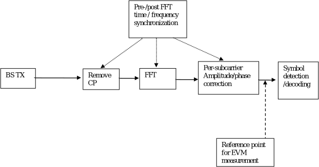 Figure B.1-1: Reference point for EVM measurement
B.2 Basic unit of measurementThe basic unit of EVM measurement is defined over one slot in the time domain and
whereT is the set of symbols with the considered modulation scheme being active within the slot,
B.3 Modified signal under test
Implicit in the definition of EVM is an assumption that the receiver is able to compensate a number of transmitter impairments. The signal under test is equalized and decoded according to:
B.4 Estimation of frequency offsetThe observation period for determining the frequency offset
B.5 Estimation of time offset
B.5.1 GeneralThe observation period for determining the sample timing difference
B.5.2 Window lengthTable B.5.2-1, B.5.2-2, B.5.2-3 specify the EVM window length ( W ) for normal CP.
Table B.5.2-1: EVM window length for normal CP, FR1, 15 kHz SCS
| Channel bandwidth (MHz) | FFT size | CP length for symbols 1-6 and 8-13 in FFT samples | EVM window length W | Ratio of W to total CP length for symbols 1-6 and 8-13 (Note) (%) |
|---|---|---|---|---|
| 3 | 256 | 18 | 8 | 44.4 |
| 5 | 512 | 36 | 14 | 40 |
| 7 | 512 | 36 | 14 | 40 |
| 10 | 1024 | 72 | 28 | 40 |
| 15 | 1536 | 108 | 44 | 40 |
| 20 | 2048 | 144 | 58 | 40 |
| 25 | 2048 | 144 | 72 | 50 |
| 30 | 3072 | 216 | 108 | 50 |
| 35 | 3072 | 216 | 108 | 50 |
| 40 | 4096 | 288 | 144 | 50 |
| 45 | 4096 | 288 | 144 | 50 |
| 50 | 4096 | 288 | 144 | 50 |
| NOTE: These percentages are informative and apply to a slot’s symbols 1 to 6 and 8 to 13. Symbols 0 and 7 have a longer CP and therefore a lower percentage. | NOTE: These percentages are informative and apply to a slot’s symbols 1 to 6 and 8 to 13. Symbols 0 and 7 have a longer CP and therefore a lower percentage. | NOTE: These percentages are informative and apply to a slot’s symbols 1 to 6 and 8 to 13. Symbols 0 and 7 have a longer CP and therefore a lower percentage. | NOTE: These percentages are informative and apply to a slot’s symbols 1 to 6 and 8 to 13. Symbols 0 and 7 have a longer CP and therefore a lower percentage. | NOTE: These percentages are informative and apply to a slot’s symbols 1 to 6 and 8 to 13. Symbols 0 and 7 have a longer CP and therefore a lower percentage. |
| Table B.5.2-2: EVM window length for normal CP, FR1, 30 kHz SCS | ||||
| Channel bandwidth (MHz) | FFT size | CP length for symbols 1-13 in FFT samples | EVM window length W | Ratio of W to total CP length for symbols 1-13 (Note) (%) |
| ------------------------------------------------------------------------------------------------------------------------------------------------ | ------------------------------------------------------------------------------------------------------------------------------------------------ | ------------------------------------------------------------------------------------------------------------------------------------------------ | ------------------------------------------------------------------------------------------------------------------------------------------------ | ------------------------------------------------------------------------------------------------------------------------------------------------ |
| 5 | 256 | 18 | 8 | 40 |
| 10 | 512 | 36 | 14 | 40 |
| 15 | 768 | 54 | 22 | 40 |
| 20 | 1024 | 72 | 28 | 40 |
| 25 | 1024 | 72 | 36 | 50 |
| 30 | 1536 | 108 | 54 | 50 |
| 35 | 1536 | 108 | 54 | 50 |
| 40 | 2048 | 144 | 72 | 50 |
| 45 | 2048 | 144 | 72 | 50 |
| 50 | 2048 | 144 | 72 | 50 |
| 60 | 3072 | 216 | 130 | 60 |
| 70 | 3072 | 216 | 130 | 60 |
| 80 | 4096 | 288 | 172 | 60 |
| 90 | 4096 | 288 | 172 | 60 |
| 100 | 4096 | 288 | 172 | 60 |
| NOTE: These percentages are informative and apply to a slot’s symbols 1 through 13. Symbol 0 has a longer CP and therefore a lower percentage. | NOTE: These percentages are informative and apply to a slot’s symbols 1 through 13. Symbol 0 has a longer CP and therefore a lower percentage. | NOTE: These percentages are informative and apply to a slot’s symbols 1 through 13. Symbol 0 has a longer CP and therefore a lower percentage. | NOTE: These percentages are informative and apply to a slot’s symbols 1 through 13. Symbol 0 has a longer CP and therefore a lower percentage. | NOTE: These percentages are informative and apply to a slot’s symbols 1 through 13. Symbol 0 has a longer CP and therefore a lower percentage. |
| Table B.5.2-3: EVM window length for normal CP, FR1, 60 kHz SCS | ||||
| Channel bandwidth (MHz) | FFT size | CP length in FFT samples | EVM window length W | Ratio of W to total CP length (Note) (%) |
| ---------------------------------------------------------------------------------------------------------------------------------------------------------------------------------------------------------------------- | ---------------------------------------------------------------------------------------------------------------------------------------------------------------------------------------------------------------------- | ---------------------------------------------------------------------------------------------------------------------------------------------------------------------------------------------------------------------- | ---------------------------------------------------------------------------------------------------------------------------------------------------------------------------------------------------------------------- | ---------------------------------------------------------------------------------------------------------------------------------------------------------------------------------------------------------------------- |
| 10 | 256 | 18 | 8 | 40 |
| 15 | 384 | 27 | 11 | 40 |
| 20 | 512 | 36 | 14 | 40 |
| 25 | 512 | 36 | 18 | 50 |
| 30 | 768 | 54 | 26 | 50 |
| 35 | 768 | 54 | 26 | 50 |
| 40 | 1024 | 72 | 36 | 50 |
| 45 | 1024 | 72 | 36 | 50 |
| 50 | 1024 | 72 | 36 | 50 |
| 60 | 1536 | 108 | 64 | 60 |
| 70 | 1536 | 108 | 64 | 60 |
| 80 | 2048 | 144 | 86 | 60 |
| 90 | 2048 | 144 | 86 | 60 |
| 100 | 2048 | 144 | 86 | 60 |
| NOTE: These percentages are informative and apply to all OFDM symbols within subframe except for symbol 0 of slot 0 and slot 2. Symbol 0 of slot 0 and slot 2 may have a longer CP and therefore a lower percentage. | NOTE: These percentages are informative and apply to all OFDM symbols within subframe except for symbol 0 of slot 0 and slot 2. Symbol 0 of slot 0 and slot 2 may have a longer CP and therefore a lower percentage. | NOTE: These percentages are informative and apply to all OFDM symbols within subframe except for symbol 0 of slot 0 and slot 2. Symbol 0 of slot 0 and slot 2 may have a longer CP and therefore a lower percentage. | NOTE: These percentages are informative and apply to all OFDM symbols within subframe except for symbol 0 of slot 0 and slot 2. Symbol 0 of slot 0 and slot 2 may have a longer CP and therefore a lower percentage. | NOTE: These percentages are informative and apply to all OFDM symbols within subframe except for symbol 0 of slot 0 and slot 2. Symbol 0 of slot 0 and slot 2 may have a longer CP and therefore a lower percentage. |
| Table B.5.2-4: EVM window length for extended CP, FR1, 60 kHz SCS | ||||
| Channel bandwidth (MHz) | FFT size | CP length in FFT samples | EVM window length W | Ratio of W to total CP length (Note) (%) |
| ------------------------------------------ | ------------------------------------------ | ------------------------------------------ | ------------------------------------------ | ------------------------------------------------ |
| 10 | 256 | 64 | 54 | 84 |
| 15 | 384 | 96 | 80 | 83 |
| 20 | 512 | 128 | 106 | 83 |
| 25 | 512 | 128 | 110 | 85.9 |
| 30 | 768 | 192 | 164 | 85.9 |
| 35 | 768 | 192 | 164 | 85.9 |
| 40 | 1024 | 256 | 220 | 85.9 |
| 45 | 1024 | 256 | 220 | 85.9 |
| 50 | 1024 | 256 | 220 | 85.9 |
| 60 | 1536 | 384 | 340 | 88.6 |
| 70 | 1536 | 384 | 340 | 88.7 |
| 80 | 2048 | 512 | 454 | 88.7 |
| 90 | 2048 | 512 | 454 | 88.7 |
| 100 | 2048 | 512 | 454 | 88.7 |
| NOTE: These percentages are informative. | NOTE: These percentages are informative. | NOTE: These percentages are informative. | NOTE: These percentages are informative. | NOTE: These percentages are informative. |
B.6 Estimation of TX chain amplitude and frequency response parameters

 The equalizer coefficients and are determined as follows:


- Calculate the complex ratios (amplitude and phase) of the post-FFT acquired signal and the post-FFT ideal signal , for each reference signal, over 10ms measurement interval. This process creates a set of complex ratios:
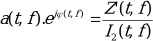 Where the post-FFT ideal signal is constructed by the measuring equipment according to the relevant TX specifications, using the following parameters: i.e. nominal demodulation reference signals, (all other modulation symbols are set to 0 V), nominal carrier frequency, nominal amplitude and phase for each applicable subcarrier, nominal timing.

2. Perform time averaging at each reference signal subcarrier of the complex ratios, the time-averaging length is 10ms measurement interval. Prior to the averaging of the phases an unwrap operation must be performed according to the following definition: The unwrap operation corrects the radian phase angles of by adding multiples of 2*PI when absolute phase jumps between consecutive time instances t i are greater than or equal to the jump tolerance of PI radians. This process creates an average amplitude and phase for each reference signal subcarrier (i.e. every second subcarrier).
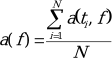
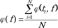
 Where N is the number of reference signal; time-domain locations ti from
 3. The equalizer coefficients for amplitude and phase and at the reference signal subcarriers are obtained by computing the moving average in the frequency domain of the time-averaged reference signal subcarriers, i.e. every second subcarrier. The moving average window size is 19 and averaging is over the DM-RS subcarriers in the allocated RBs. For DM-RS subcarriers at or near the edge of the channel , or when the number of available DM-RS subcarriers within a set of contiguously allocated RBs is smaller than the moving average window size, the window size is reduced accordingly as per figure B.6-1.
4. Perform linear interpolation from the equalizer coefficients and to compute coefficients , for each subcarrier.
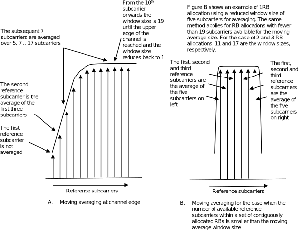 Figure B.6-1: Reference subcarrier smoothing in the frequency domain
B.7 Averaged EVMEVM is averaged over all allocated downlink resource blocks with the considered modulation scheme in the frequency domain, and a minimum of
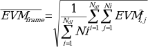 - Where Ni is the number of resource blocks with the considered modulation scheme in slot i .- The EVM requirements shall be tested against the maximum of the RMS average at the window W extremities of the EVM measurements:


- Thus is calculated using in the expressions above and is calculated using in the calculation.
- Thus we get:
be the number of slots with downlink symbols within a 10 ms measurement interval, the averaging in the time domain can be calculated from slots of different 10 ms measurement intervals and should have a minimum of slots averaging length where is the number of slots in a 10 ms measurement interval.- is derived by: Square the EVM results in each 10 ms measurement interval. Sum the squares, divide the sum by the number of EVM relevant locations, square-root the quotient (RMS). is the number of resource blocks with the considered modulation scheme in slot i.-The is calculated, using the maximum of at the window W extremities. Thus is calculated using and is calculated using (l and h, low and high; where low is the timing and and high is the timing ). slots, consider the minimum integer number of 10 ms measurement intervals, where is determined by. for 15 kHz SCS, for 30 kHz SCS and for 60 kHz SCS normal CP. - Unite by RMS.
B.8 Averaged EVM for FR1 SBFD-capable BSEVM is averaged over all allocated downlink resource blocks with the considered modulation scheme in the frequency domain, and a minimum of
For SBFD slot and non-SBFD slot, the EVM measurement are conducted separately. For SBFD slot, only resource blocks allocated to downlink subband(s) shall be measured.For SBFD, let
- Unite by RMS.
B.9 Interference model for enhanced performance requirements for PUSCH with synchronous interference
B.9.1 Interference to Noise ratio (INR)
Each inter-cell interferer involved in enhanced performance requirements is characterized by its associated interferer to noise ratio (INR) value:
B.9.2 Interference model for synchronous scenario
This clause provides interference modelling for each explicitly modelled inter-cell interferer in the requirement scenario where the inter-cell interferer(s) are time-synchronous with the tested signal. In each subframe, each interferer shall transmit 16QAM randomly modulated data over the entire PUSCH region and the same resource blocks as the tested signal. The demodulation reference signal (DM-RS), configured according to Table 8.2.16.1-1 for enhanced performance requirements is transmitted associated with the transmission of PUSCH.
Annex C (normative):
Error Vector Magnitude (FR2)
C.1 Reference point for measurement
The EVM shall be measured at the point after the FFT and a zero-forcing (ZF) equalizer in the receiver, as depicted in figure C.1-1 below.
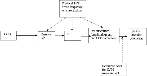 Figure C.1-1: Reference point for EVM measurement
C.2 Basic unit of measurementThe basic unit of EVM measurement is defined over one slot in the time domain and
where
C.3 Modified signal under test
Implicit in the definition of EVM is an assumption that the receiver is able to compensate a number of transmitter impairments. The signal under test is equalized and decoded according to:
C.4 Estimation of frequency offsetThe observation period for determining the frequency offset
C.5 Estimation of time offset
C.5.1 GeneralThe observation period for determining the sample timing difference
C.5.2 Window lengthTable C.5.2-1, Table C.5.2-2, Table C.5.2-2a and Table C.5.2-2b specify the EVM window length ( W ) for normal CP for FR2.
Table C.5.2-1: EVM window length for normal CP, FR2, 60 kHz SCS
| Channel bandwidth (MHz) | FFT size | CP length in FFT samples | EVM window length W | Ratio of W to total CP length (Note) (%) |
|---|---|---|---|---|
| 50 | 1024 | 72 | 36 | 50 |
| 100 | 2048 | 144 | 72 | 50 |
| 200 | 4096 | 288 | 144 | 50 |
| NOTE: These percentages are informative and apply to all OFDM symbols within subframe except for symbol 0 of slot 0 and slot 2. Symbol 0 of slot 0 and slot 2 may have a longer CP and therefore a lower percentage. | NOTE: These percentages are informative and apply to all OFDM symbols within subframe except for symbol 0 of slot 0 and slot 2. Symbol 0 of slot 0 and slot 2 may have a longer CP and therefore a lower percentage. | NOTE: These percentages are informative and apply to all OFDM symbols within subframe except for symbol 0 of slot 0 and slot 2. Symbol 0 of slot 0 and slot 2 may have a longer CP and therefore a lower percentage. | NOTE: These percentages are informative and apply to all OFDM symbols within subframe except for symbol 0 of slot 0 and slot 2. Symbol 0 of slot 0 and slot 2 may have a longer CP and therefore a lower percentage. | NOTE: These percentages are informative and apply to all OFDM symbols within subframe except for symbol 0 of slot 0 and slot 2. Symbol 0 of slot 0 and slot 2 may have a longer CP and therefore a lower percentage. |
| Table C.5.2-2: EVM window length for normal CP, FR2, 120 kHz SCS | ||||
| Channel bandwidth (MHz) | FFT size | CP length in FFT samples | EVM window length W | Ratio of W to total CP length (Note) (%) |
| ------------------------------------------------------------------------------------------------------------------------------------------------------------------------------------------------------------------------ | ------------------------------------------------------------------------------------------------------------------------------------------------------------------------------------------------------------------------ | ------------------------------------------------------------------------------------------------------------------------------------------------------------------------------------------------------------------------ | ------------------------------------------------------------------------------------------------------------------------------------------------------------------------------------------------------------------------ | ------------------------------------------------------------------------------------------------------------------------------------------------------------------------------------------------------------------------ |
| 50 | 512 | 36 | 18 | 50 |
| 100 | 1024 | 72 | 36 | 50 |
| 200 | 2048 | 144 | 72 | 50 |
| 400 | 4096 | 288 | 144 | 50 |
| NOTE 1: These percentages are informative and apply to all OFDM symbols within subframe except for symbol 0 of slot 0 and slot 4. Symbol 0 of slot 0 and slot 4 may have a longer CP and therefore a lower percentage. | NOTE 1: These percentages are informative and apply to all OFDM symbols within subframe except for symbol 0 of slot 0 and slot 4. Symbol 0 of slot 0 and slot 4 may have a longer CP and therefore a lower percentage. | NOTE 1: These percentages are informative and apply to all OFDM symbols within subframe except for symbol 0 of slot 0 and slot 4. Symbol 0 of slot 0 and slot 4 may have a longer CP and therefore a lower percentage. | NOTE 1: These percentages are informative and apply to all OFDM symbols within subframe except for symbol 0 of slot 0 and slot 4. Symbol 0 of slot 0 and slot 4 may have a longer CP and therefore a lower percentage. | NOTE 1: These percentages are informative and apply to all OFDM symbols within subframe except for symbol 0 of slot 0 and slot 4. Symbol 0 of slot 0 and slot 4 may have a longer CP and therefore a lower percentage. |
| Table C.5.2-2a: EVM window length for normal CP, FR2-2, 480 kHz SCS | ||||
| Channel bandwidth (MHz) | FFT size | CP length in FFT samples | EVM window length W | Ratio of W to total CP length (Note) (%) |
| ------------------------------------------------------------------------------------------------------------------------------------------------------------------------------------------------------------------------ | ------------------------------------------------------------------------------------------------------------------------------------------------------------------------------------------------------------------------ | ------------------------------------------------------------------------------------------------------------------------------------------------------------------------------------------------------------------------ | ------------------------------------------------------------------------------------------------------------------------------------------------------------------------------------------------------------------------ | ------------------------------------------------------------------------------------------------------------------------------------------------------------------------------------------------------------------------ |
| 400 | 1024 | 72 | [36] | [50] |
| 800 | 2048 | 144 | [72] | [50] |
| 1600 | 4096 | 288 | [144] | [50] |
| NOTE 1: These percentages are informative and apply to all OFDM symbols within subframe except for symbol 0 of slot 0 and slot 4. Symbol 0 of slot 0 and slot 4 may have a longer CP and therefore a lower percentage. | NOTE 1: These percentages are informative and apply to all OFDM symbols within subframe except for symbol 0 of slot 0 and slot 4. Symbol 0 of slot 0 and slot 4 may have a longer CP and therefore a lower percentage. | NOTE 1: These percentages are informative and apply to all OFDM symbols within subframe except for symbol 0 of slot 0 and slot 4. Symbol 0 of slot 0 and slot 4 may have a longer CP and therefore a lower percentage. | NOTE 1: These percentages are informative and apply to all OFDM symbols within subframe except for symbol 0 of slot 0 and slot 4. Symbol 0 of slot 0 and slot 4 may have a longer CP and therefore a lower percentage. | NOTE 1: These percentages are informative and apply to all OFDM symbols within subframe except for symbol 0 of slot 0 and slot 4. Symbol 0 of slot 0 and slot 4 may have a longer CP and therefore a lower percentage. |
| Table C.5.2-2b: EVM window length for normal CP, FR2-2, 960 kHz SCS | ||||
| Channel bandwidth (MHz) | FFT size | CP length in FFT samples | EVM window length W | Ratio of W to total CP length (Note) (%) |
| ------------------------------------------------------------------------------------------------------------------------------------------------------------------------------------------------------------------------ | ------------------------------------------------------------------------------------------------------------------------------------------------------------------------------------------------------------------------ | ------------------------------------------------------------------------------------------------------------------------------------------------------------------------------------------------------------------------ | ------------------------------------------------------------------------------------------------------------------------------------------------------------------------------------------------------------------------ | ------------------------------------------------------------------------------------------------------------------------------------------------------------------------------------------------------------------------ |
| 400 | 512 | 36 | [18] | [50] |
| 800 | 1024 | 72 | [36] | [50] |
| 1600 | 2048 | 144 | [72] | [50] |
| 2000 | [2048] | [144] | [72] | [50] |
| NOTE 1: These percentages are informative and apply to all OFDM symbols within subframe except for symbol 0 of slot 0 and slot 4. Symbol 0 of slot 0 and slot 4 may have a longer CP and therefore a lower percentage. | NOTE 1: These percentages are informative and apply to all OFDM symbols within subframe except for symbol 0 of slot 0 and slot 4. Symbol 0 of slot 0 and slot 4 may have a longer CP and therefore a lower percentage. | NOTE 1: These percentages are informative and apply to all OFDM symbols within subframe except for symbol 0 of slot 0 and slot 4. Symbol 0 of slot 0 and slot 4 may have a longer CP and therefore a lower percentage. | NOTE 1: These percentages are informative and apply to all OFDM symbols within subframe except for symbol 0 of slot 0 and slot 4. Symbol 0 of slot 0 and slot 4 may have a longer CP and therefore a lower percentage. | NOTE 1: These percentages are informative and apply to all OFDM symbols within subframe except for symbol 0 of slot 0 and slot 4. Symbol 0 of slot 0 and slot 4 may have a longer CP and therefore a lower percentage. |
| Table C.5.2-3: EVM window length for extended CP, FR2, 60 kHz SCS | ||||
| Channel bandwidth (MHz) | FFT size | CP length in FFT samples | EVM window length W | Ratio of W to total CP length (Note) (%) |
| ------------------------------------------ | ------------------------------------------ | ------------------------------------------ | ------------------------------------------ | ------------------------------------------------ |
| 50 | 1024 | 256 | 220 | 85.9 |
| 100 | 2048 | 512 | 440 | 85.9 |
| 200 | 4096 | 1024 | 880 | 85.9 |
| NOTE: These percentages are informative. | NOTE: These percentages are informative. | NOTE: These percentages are informative. | NOTE: These percentages are informative. | NOTE: These percentages are informative. |
C.6 Estimation of TX chain amplitude and frequency response parameters
The equalizer coefficients and are determined as follows:
- Calculate the complex ratios (amplitude and phase) of the post-FFT acquired signal and the post-FFT ideal signal , for each reference signal, over 10ms measurement intervals. This process creates a set of complex ratios:
Where the post-FFT ideal signal is constructed by the measuring equipment according to the relevant TX specifications, using the following parameters:
- nominal demodulation reference signals and nominal PT-RS if present (all other modulation symbols are set to 0 V),
- nominal carrier frequency,
- nominal amplitude and phase for each applicable subcarrier,
- nominal timing.
2. Perform time averaging at each reference signal subcarrier of the complex ratios, the time-averaging length is 10ms measurement interval. Prior to the averaging of the phases an unwrap operation must be performed according to the following definition: The unwrap operation corrects the radian phase angles of by adding multiples of 2*PI when absolute phase jumps between consecutive time instances t i are greater than or equal to the jump tolerance of PI radians. This process creates an average amplitude and phase for each reference signal subcarrier (i.e. every second subcarrier).
Where N is the number of reference signal time-domain locations ti from
3. The equalizer coefficients for amplitude and phase and at the reference signal subcarriers are obtained by computing the moving average in the frequency domain of the time-averaged reference signal subcarriers, i.e. every second subcarrier. The moving average window size is 19 and averaging is over the DM-RS subcarriers in allocated RBs. For DM-RS subcarriers at or near the edge of the channel, or when the number of available DM-RS subcarriers within a set of contiguously allocated RBs is smaller than the moving average window size, the window size is reduced accordingly as per figure C.6-1.
4.Perform linear interpolation from the equalizer coefficients and to compute coefficients , for each subcarrier. To account for the common phase error (CPE) experienced in millimetre wave frequencies, 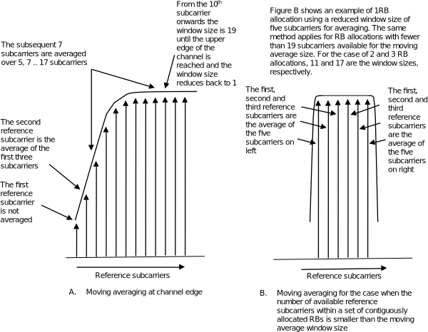 Figure C.6-1: Reference subcarrier smoothing in the frequency domain
C.7 Averaged EVMEVM is averaged over all allocated downlink resource blocks with the considered modulation scheme in the frequency domain, and a minimum of
- Unite by RMS.
C.8 Averaged EVM for FR2-1 SBFD-capable BSEVM is averaged over all allocated downlink resource blocks with the considered modulation scheme in the frequency domain, and a minimum of
For SBFD slot and non-SBFD slot, the EVM measurement are conducted separately. For SBFD slot, only resource blocks allocated to downlink subband(s) shall be measured.For SBFD, let
- Unite by RMS.
Annex D (normative):
Characteristics of the interfering signals
The interfering signal shall be a PUSCH containing data and DM-RS symbols. Normal cyclic prefix is used. The data content shall be uncorrelated to the wanted signal and modulated according to clause 6 of TS38.211 [9]. Mapping of PUSCH modulation to receiver requirement are specified in table D-1.
Table D-1: Modulation of the interfering signal
| Receiver requirement | Modulation |
|---|---|
| In-channel selectivity | 16QAM |
| Adjacent channel selectivity and narrow-band blocking | QPSK |
| General blocking | QPSK |
| Receiver intermodulation | QPSK |
| In-channel adjacent subband blocking for SBFD | QPSK |
Annex E:
Void
Annex F (normative):
Relationship between EIRP based regulatory requirements and 3GPP requirements
F.1 GeneralThis annex applies to FR1 BS type 1-C , BS type 1-H and BS type 1-O .
Some regional requirements are defined per effective isotropic radiated power (EIRP), which is a combination of the transmitted power (or in some cases spectral density) and the effective antenna gain which is a site-specific condition. Such requirements may be applied per antenna, per cell, or per base station. It shall be noted that the definition of BS or cell may differ between regulations.The regulations are based on the assumption on BS type 1-C conducted requirements and a passive antenna and must be interpreted for active antenna systems that have active beamforming. This annex describes how the power per connector and sum power over TAB connectors can be related to such requirements. Where the regulator prescribes a method for EIRP calculation, that method supersedes the proposed assessment in this annex.
F.2 Relationship between EIRP based regulatory requirements and conducted requirements
When 3GPP specifications mandate manufacturer declarations of the (conducted) output power or power spectral density per connector for the base station under the reference conditions stated as a way to accommodate the referred regional requirements without putting requirements on the local site conditions. For the case when the base station manufacturer maximum output power or unwanted emission declarations apply per connector, the maximum EIRP can be estimated using the following formulas:EIRP per antenna (applicable for BS type 1-C ): P EIRP = P Tx + G AntEIRP per cell or per BS (applicable for BS type 1-H ): P EIRPcell =10 * log (∑10 PEIRPn/10 ) In case the EIRP requirement is set per polarization, the summation shall be made per polarization.- "P EIRP " is the resulting effective isotropic radiated power (or radiated power spectral density) resulting from the power (or power spectral density) declared by the manufacturer in dBm (or dBm/measurement BW).- "P Tx " is the conducted power or power spectral density declared by the manufacturer in dBm (or dBm/measurement BW).- "G Ant " is the effective antenna gain, calculated as the antenna gain (dBi) minus the loss of the site infrastructure connecting the BS antenna connector with the antenna (dB) for the applied frequency. The antenna nominal gain is only applicable within a certain frequency range. For BS type 1-H , G Ant shall be an assumption on the gain of a passive antenna system in order to provide a total power emissions level comparable to the level obtained when a BS type 1-C is connected to a passive antenna. A typical example of a passive antenna gain, as used for BS type 1-O , is 17 dBi.- “n” is the index number of the co-located antennas illuminating the same cell. P EIRPn is the P EIRP of the n th antenna.
- “Cell” is in this annex used in the sense that it is the limited geographical area covered by the carrier transmitted from one site.
F.3 Relationship between EIRP based regulatory requirements and OTA requirementsThe regulations set an EIRP limit considering a passive antenna BS. Although the gain of passive antennas may vary somewhat, the variation is in the order of a few dBs. The gain variation of a BS type 1-O may be much larger. However, BS type 1-O unwanted emissions requirements are defined as TRP, since TRP impacts co-existence properties.
In order to relate the EIRP values in the specifications to TRP, a fixed assumption has been made on the gain of a typical passive BS antenna. Thus, the maximum TRP can be estimated using the following formulas:TRP limit per antenna: P TRP, antenna = P EIRP - G AntTRP limit per cell or per BS: P TRP =P TRP,antenna + 9 dBIt is noted that the BS type 1-O architecture assumes that a BS subject to OTA requirements will have at least 8 antennas. In case the TRP requirement is set per polarization, the summation shall be made per polarization.- "P EIRP " is the effective isotropic radiated power (or radiated power spectral density) set in the regulation (assuming a passive BS antenna) in dBm (or dBm/measurement BW).- "G Ant " is the effective antenna gain, the antenna gain (dBi) is a fixed reference value of 17 dBi. Directivity value should be used in above equations, however with all antenna losses are assumed zero then we can use effective antenna gain.
Annex G (Normative):
Propagation conditions
G.1 Static propagation condition
The propagation for the static performance measurement is an Additive White Gaussian Noise (AWGN) environment. No fading or multi-paths exist for this propagation model.
G.1.1 BS Receiver with 2Rx
For 2 port transmission the channel matrix is defined in the frequency domain by
G.2 Multi-path fading propagation conditions
The multipath propagation conditions consist of several parts:
- A delay profile in the form of a “tapped delay-line”, characterized by a number of taps at fixed positions on a sampling grid. The profile can be further characterized by the r.m.s. delay spread and the maximum delay spanned by the taps.
- A combination of channel model parameters that include the Delay profile and the Doppler spectrum that is characterized by a classical spectrum shape and a maximum Doppler frequency.
- Different models are used for FR1, FR2(24.25 GHz – 71 GHz).
G.2.1 Delay profiles
The delay profiles are simplified from the TR 38.901 [16] TDL models. The simplification steps are shown below for information. These steps are only used when new delay profiles are created. Otherwise, the delay profiles specified in G.2.1.1, G.2.1.2 and G.2.1.3 can be used as such. Step 1: Use the original TDL model from TR 38.901 [16]. Step 2: Re-order the taps in ascending delays. Step 3: Perform delay scaling according to the procedure described in clause 7.7.3 in TR 38.901 [16]. Step 4: Apply the quantization to the delay resolution 5 ns. This is done simply by rounding the tap delays to the nearest multiple of the delay resolution. Step 5: If multiple taps are rounded to the same delay bin, merge them by calculating their linear power sum. Step 6: If there are more than 12 taps in the quantized model, merge the taps as follows
- Find the weakest tap from all taps (both merged and unmerged taps are considered)
- If there are two or more taps having the same value and are the weakest, select the tap with the smallest delay as the weakest tap.
- When the weakest tap is the first delay tap, merge taps as follows
- Update the power of the first delay tap as the linear power sum of the weakest tap and the second delay tap.
- Remove the second delay tap.
- When the weakest tap is the last delay tap, merge taps as follows
- Update the power of the last delay tap as the linear power sum of the second-to-last tap and the last tap.
- Remove the second-to-last tap.
- Otherwise
- For each side of the weakest tap, identify the neighbour tap that has the smaller delay difference to the weakest tap.
- When the delay difference between the weakest tap and the identified neighbour tap on one side equals the delay difference between the weakest tap and the identified neighbour tap on the other side.
- Select the neighbour tap that is weaker in power for merging.
- Otherwise, select the neighbour tap that has smaller delay difference for merging.
- To merge, the power of the merged tap is the linear sum of the power of the weakest tap and the selected tap.
- When the selected tap is the first tap, the location of the merged tap is the location of the first tap. The weakest tap is removed.
- When the selected tap is the last tap, the location of the merged tap is the location of the last tap. The weakest tap is removed.
- Otherwise, the location of the merged tap is based on the average delay of the weakest tap and selected tap. If the average delay is on the sampling grid, the location of the merged tap is the average delay. Otherwise, the location of the merged tap is rounded towards the direction of the selected tap (e.g. 10 ns & 20 ns 15 ns, 10 ns & 25 ns 20 ns, if 25 ns had higher or equal power; 15 ns, if 10 ns had higher power) . The weakest tap and the selected tap are removed.
- Repeat step 6 until the final number of taps is 12. Step 7: Round the amplitudes of taps to one decimal (e.g. -8.78 dB -8.8 dB) Step 8: If the delay spread has slightly changed due to the tap merge, adjust the final delay spread by increasing or decreasing the power of the last tap so that the delay spread is corrected. Step 9: Re-normalize the highest tap to 0 dB. Note 1: Some values of the delay profile created by the simplification steps may differ from the values in tables G.2.1.1-2, G.2.1.1-3, G.2.1.1-4, G.2.1.2-2, G.2.1.2-3, G.2.1.2-4 and G.2.1.2-5 for the corresponding model. Note 2: For Step 5 and Step 6, the power values are expressed in the linear domain using 6 digits of precision. The operations are in the linear domain.
G.2.1.1 Delay profiles for FR1
The delay profiles for FR1 are selected to be representative of low, medium and high delay spread environment. The resulting model parameters are specified in table G.2.1.1-1 and the tapped delay line models are specified in tables G.2.1.1-2 ~ G.2.1.1-4. Table G.2.1.1-1: Delay profiles for NR channel models
| Model | Number of channel taps | Delay spread (r.m.s.) | Maximum excess tap delay (span) | Delay resolution |
|---|---|---|---|---|
| TDLA30 | 12 | 30 ns | 290 ns | 5 ns |
| TDLB100 | 12 | 100 ns | 480 ns | 5 ns |
| TDLC300 | 12 | 300 ns | 2595 ns | 5 ns |
| Table G.2.1.1-2: TDLA30 (DS = 30 ns) | ||||
| Tap # | Delay (ns) | Power (dB) | Fading distribution | |
| --------- | -------------- | -------------- | ----------------------- | |
| 1 | 0 | -15.5 | Rayleigh | |
| 2 | 10 | 0 | Rayleigh | |
| 3 | 15 | -5.1 | Rayleigh | |
| 4 | 20 | -5.1 | Rayleigh | |
| 5 | 25 | -9.6 | Rayleigh | |
| 6 | 50 | -8.2 | Rayleigh | |
| 7 | 65 | -13.1 | Rayleigh | |
| 8 | 75 | -11.5 | Rayleigh | |
| 9 | 105 | -11.0 | Rayleigh | |
| 10 | 135 | -16.2 | Rayleigh | |
| 11 | 150 | -16.6 | Rayleigh | |
| 12 | 290 | -26.2 | Rayleigh | |
| Table G.2.1.1-3: TDLB100 (DS = 100 ns) | ||||
| Tap # | Delay (ns) | Power (dB) | Fading distribution | |
| --------- | -------------- | -------------- | ----------------------- | |
| 1 | 0 | 0 | Rayleigh | |
| 2 | 10 | -2.2 | Rayleigh | |
| 3 | 20 | -0.6 | Rayleigh | |
| 4 | 30 | -0.6 | Rayleigh | |
| 5 | 35 | -0.3 | Rayleigh | |
| 6 | 45 | -1.2 | Rayleigh | |
| 7 | 55 | -5.9 | Rayleigh | |
| 8 | 120 | -2.2 | Rayleigh | |
| 9 | 170 | -0.8 | Rayleigh | |
| 10 | 245 | -6.3 | Rayleigh | |
| 11 | 330 | -7.5 | Rayleigh | |
| 12 | 480 | -7.1 | Rayleigh | |
| Table G.2.1.1-4: TDLC300 (DS = 300 ns) | ||||
| Tap # | Delay (ns) | Power (dB) | Fading distribution | |
| --------- | -------------- | -------------- | ----------------------- | |
| 1 | 0 | -6.9 | Rayleigh | |
| 2 | 65 | 0 | Rayleigh | |
| 3 | 70 | -7.7 | Rayleigh | |
| 4 | 190 | -2.5 | Rayleigh | |
| 5 | 195 | -2.4 | Rayleigh | |
| 6 | 200 | -9.9 | Rayleigh | |
| 7 | 240 | -8.0 | Rayleigh | |
| 8 | 325 | -6.6 | Rayleigh | |
| 9 | 520 | -7.1 | Rayleigh | |
| 10 | 1045 | -13.0 | Rayleigh | |
| 11 | 1510 | -14.2 | Rayleigh | |
| 12 | 2595 | -16.0 | Rayleigh |
G.2.1.2 Delay profiles for FR2
The delay profiles for FR2 are specified in table G.2.1.2-1 and the tapped delay line models are specified in table G.2.1.2-2 - G.2.1.2-5… Table G.2.1.2-1: Delay profiles for NR channel models
| Model | Number of channel taps | Delay spread (r.m.s.) | Maximum excess tap delay (span) | Delay resolution |
|---|---|---|---|---|
| TDLA30 | 12 | 30 ns | 290 ns | 5 ns |
| TDLA10 | 16 | 10 ns | 96 ns | 2 ns |
| TDLD10 | 10 | 10 ns | 126 ns | 2 ns |
| TDLD30 | 10 | 30 ns | 375 ns | 5 ns |
| Table G.2.1.2-2: TDLA30 (DS = 30 ns) | ||||
| Tap # | Delay (ns) | Power (dB) | Fading distribution | |
| --------- | -------------- | -------------- | ----------------------- | |
| 1 | 0 | -15.5 | Rayleigh | |
| 2 | 10 | 0 | Rayleigh | |
| 3 | 15 | -5.1 | Rayleigh | |
| 4 | 20 | -5.1 | Rayleigh | |
| 5 | 25 | -9.6 | Rayleigh | |
| 6 | 50 | -8.2 | Rayleigh | |
| 7 | 65 | -13.1 | Rayleigh | |
| 8 | 75 | -11.5 | Rayleigh | |
| 9 | 105 | -11.0 | Rayleigh | |
| 10 | 135 | -16.2 | Rayleigh | |
| 11 | 150 | -16.6 | Rayleigh | |
| 12 | 290 | -26.2 | Rayleigh | |
| Table G.2.1.2-3: TDLA10 (DS = 10 ns) | ||||
| Tap # | Delay (ns] | Power (dB) | Fading distribution | |
| --------- | -------------- | -------------- | ----------------------- | |
| 1 | 0 | -16.1 | Rayleigh | |
| 2 | 4 | 0 | ||
| 3 | 6 | -4 | ||
| 4 | 8 | -10.2 | ||
| 5 | 16 | -18.6 | ||
| 6 | 18 | -9.3 | ||
| 7 | 22 | -13.7 | ||
| 8 | 24 | -17.9 | ||
| 9 | 26 | -13.5 | ||
| 10 | 30 | -14 | ||
| 11 | 40 | -15.4 | ||
| 12 | 44 | -18.9 | ||
| 13 | 46 | -21.0 | ||
| 14 | 48 | -21.6 | ||
| 15 | 50 | -19.3 | ||
| 16 | 96 | -25.9 | ||
| Table G.2.1.2-4: TDLD10 (DS = 10 ns) | ||||
| Tap # | Delay (ns] | Power (dB) | Fading distribution | |
| ----------------------------------------------- | ----------------------------------------------- | ----------------------------------------------- | ----------------------------------------------- | |
| 1 | 0 | -0.2 | LOS | |
| 1 | 0 | -12.4 | Rayleigh | |
| 2 | 6 | -21.1 | ||
| 3 | 14 | -16.75 | ||
| 4 | 18 | -18.3 | ||
| 5 | 26 | -22 | ||
| 6 | 40 | -27.9 | ||
| 7 | 80 | -23.7 | ||
| 8 | 94 | -24.9 | ||
| 9 | 98 | -30.0 | ||
| 10 | 126 | -27.7 | ||
| Note 1: Tap #1 follows a Ricean distribution. | Note 1: Tap #1 follows a Ricean distribution. | Note 1: Tap #1 follows a Ricean distribution. | Note 1: Tap #1 follows a Ricean distribution. | |
| Table G.2.1.2-5: TDLD30 (DS = 30 ns) | ||||
| Tap # | Delay (ns] | Power (dB) | Fading distribution | |
| ----------------------------------------------- | ----------------------------------------------- | ----------------------------------------------- | ----------------------------------------------- | |
| 1 | 0 | -0.2 | LOS | |
| 1 | 0 | -12.4 | Rayleigh | |
| 2 | 20 | -21 | ||
| 3 | 40 | -16.7 | ||
| 4 | 55 | -18.3 | ||
| 5 | 80 | -21.9 | ||
| 6 | 120 | -27.8 | ||
| 7 | 240 | -23.6 | ||
| 8 | 285 | -24.8 | ||
| 9 | 290 | -30.0 | ||
| 10 | 375 | -27.6 | ||
| Note 1: Tap #1 follows a Ricean distribution. | Note 1: Tap #1 follows a Ricean distribution. | Note 1: Tap #1 follows a Ricean distribution. | Note 1: Tap #1 follows a Ricean distribution. |
G.2.2 Combinations of channel model parameters
The propagation conditions used for the performance measurements in multi-path fading environment are indicated as a combination of a channel model name and a maximum Doppler frequency, i.e., TDLA<DS>-<Doppler>, TDLB<DS>-<Doppler> or TDLC<DS>-<Doppler> where ‘<DS>’ indicates the desired delay spread and ‘<Doppler>’ indicates the maximum Doppler frequency (Hz). Table G.2.2-1 and G.2.2-2 show the propagation conditions that are used for the performance measurements in multi-path fading environment for low, medium and high Doppler frequencies for FR1 and FR2 (24.25 GHz – 71 GHz), respectively. Table G.2.2-1: Channel model parameters for FR1
| Combination name | Tapped delay line model | Maximum Doppler frequency |
|---|---|---|
| TDLA30-5 | TDLA30 | 5 Hz |
| TDLA30-10 | TDLA30 | 10 Hz |
| TDLB100-400 | TDLB100 | 400 Hz |
| TDLC300-100 | TDLC300 | 100 Hz |
| TDLC300-600 | TDLC300 | 600 Hz |
| TDLC300-1200 | TDLC300 | 1200 Hz |
| Table G.2.2-2: Channel model parameters for FR2 | ||
| Combination name | Tapped delay line model | Maximum Doppler frequency |
| -------------------- | --------------------------- | ----------------------------- |
| TDLA30-75 | TDLA30 | 75 Hz |
| TDLA30-300 | TDLA30 | 300 Hz |
| TDLA10-650 | TDLA10 | 650 Hz |
| TDLA30-650 | TDLA30 | 650 Hz |
| TDLD10-200 | TDLD10 | 200 Hz |
| TDLD30-200 | TDLD30 | 200 Hz |
| TDLD30-35 | TDLD30 | 35 Hz |
G.2.3 MIMO Channel Correlation Matrices
The MIMO channel correlation matrices defined in G.2.3 apply for the antenna configuration using uniform linear arrays at both gNB and UE and for the antenna configuration using cross polarized antennas.
G.2.3.1 MIMO Correlation Matrices using Uniform Linear Array (ULA)
The MIMO channel correlation matrices defined in G.2.3.1 apply for the antenna configuration using uniform linear array (ULA) at both gNB and UE.
G.2.3.1.1 Definition of MIMO Correlation Matrices
Table G.2.3.1.1-1 defines the correlation matrix for the gNB: Table G.2.3.1.1-1: gNB correlation matrix
| One antenna | Two antennas | Four antennas | Eight antennas | |
|---|---|---|---|---|
| gNode B Correlation | ||||
| Table G.2.3.1.1-2 defines the correlation matrix for the UE: | ||||
| Table G.2.3.1.1-2: UE correlation matrix | ||||
| One antenna | Two antennas | Four antennas | ||
| ---------------- | --------------- | -------------------------- | -------------------------------------------------------------------------------------------------------------------------------------------------------------------------------------------------------------------------------- | |
| UE Correlation | $R_{UE}=\left(\right)\$ | |||
 Table G.2.3.1.1-3 defines the channel spatial correlation matrix. The parameters α and β in Table G.2.3.1.1-3 defines the spatial correlation between the antennas at the gNB and UE respectively. Table G.2.3.1.1-3 defines the channel spatial correlation matrix. The parameters α and β in Table G.2.3.1.1-3 defines the spatial correlation between the antennas at the gNB and UE respectively. |
||||
|
||||
| Table G.2.3.1.1-3: correlation matrices | ||||
| 1x2 case | ||||
| ------------ | ------------------------------------------------------------------------------------------------------------------------------------------------------------------------------------------------------------------------------------------------------------------------------------------------------------------------------------------------------------------------------------------------------------------------------------------------------------------------------------------------------------------------------------------------------------------------------------------------------------------------------------------------------------------------------------------------------------------------------------------------------------------------------------------------------------------------------------------------------------------------------------------------------------------------------------------------------------------------------------------------------------------------------------------------------------------------------------------------------------------------------------------------------------------------ | |||
| 1x4 case | ||||
| 1x8 case | ||||
| 2x2 case | ||||
| 2x4 case | ||||
| 2x8 case | ||||
| 4x4 case | ||||
For cases with more antennas at either gNB or UE or both, the channel spatial correlation matrix can still be expressed as the Kronecker product of and according to .
G.2.3.1.2 MIMO Correlation Matrices at High, Medium and Low Level

 The and for different correlation types are given in Table G.2.3.1.2-1.
Table G.2.3.1.2-1: Correlation for High Medium and Low Level
The and for different correlation types are given in Table G.2.3.1.2-1.
Table G.2.3.1.2-1: Correlation for High Medium and Low Level
| Low correlation | Low correlation | Medium Correlation | Medium Correlation | High Correlation | High Correlation |
|---|---|---|---|---|---|
| 0 | 0 | 0.9 | 0.3 | 0.9 | 0.9 |
| The correlation matrices for high, medium and low correlation are defined in Table G.2.3.1.2-2, G.2.3.1.2-3 and G.2.3.1.2-4 as below. | |||||
| The values in Table G.2.3.1.2-2 have been adjusted for the 2x4 and 4x4 high correlation cases to insure the correlation matrix is positive semi-definite after round-off to 4-digit precision. This is done using the equation: | |||||
| Where the value “a” is a scaling factor such that the smallest value is used to obtain a positive semi-definite result. For the 2x4 high correlation case, a=0.00010. For the 4x4 high correlation case, a=0.00012. | |||||
| The same method is used to adjust the 4x4 medium correlation matrix in Table G.2.3.1.2-3 to insure the correlation matrix is positive semi-definite after round-off to 4-digit precision with a =0.00012. | |||||
| Table G.2.3.1.2-2: MIMO correlation matrices for high correlation | |||||
| 1x2 case | |||||
| ------------ | ------------------------------------------------------------------------------------------------------------------------------------------------------------------------------------------------------------------------------------------------------------------------------------------------------------------------------------------------------------------------------------------------------------------------------------------------------------------------------------------------------------------------------------------------------------------------------------------------------------------------------------------------------------------------------------------------------------------------------------------------------------------------------------------------------------------------------------------------------------------------------------------------------------------------------------------------------------------------- | ||||
| 2x2 case | |||||
| 2x4 case | |||||
| 4x4 case | $R_{high}=\left[\right]\left[\right]\left[\right]\left[\right]\left[\right]\left[\right]\left[\right]\left[\right]\left[\right]\left[\right]\left[\right]\left[\right]\left[\right]\left[\right]\left[\right]\$ | ||||
| Table G.2.3.1.2-3: MIMO correlation matrices for medium correlation | |||||
| 1x2 case | [N/A] | ||||
| ------------ | ----------------------------------------------------------------------------------------------------------------------------------------------------------------------------------------------------------------------------------------------------------------------------------------------------------------------------------------------------------------------------------------------------------------------------------------------------------------------------------------------------------------------------------------------------------------------------------------------------------------------------------------------------------------------------------------------------------------------------------------------------------------------------------------------------------------------------------------------------------------------------------------------------------------------------------------------------------------------------------------------------------------------------------------------------------------------------------------------------------------------------------------------------------------------------------------------------------------------------------------------------------------------------------------------------------------------------------------------------------------------------------------------------------------------------------------------------------------------------------------------------------------------------------------------------------------------------------------------------------------------------------------------------------------------------------------------------------------------------------------------------------------------------------------------------------------------------------------------------------------------------------------------------------------------------------------------------------------------------------------------------------------------------------------------------------------------------------------------------------------------------------------------------------------------------------------------------------------------------------------------------------------------------------------------------------------------------------------------------------------------------------------------------------------------------------------------------------------------------------------------------------------------------------------------------------------------------------------------------------------------------------------------------------------------------------------------------------------------------------------------------------------------------------------------------------------------------------------------------------------------------------------------------------------------------------------------------------------------------------------------------------------------------------------------------------------------------------------------------------------------------------------------------------------------------------------------------------------------------------------------------------------------------------------------------------------------------------------------------------------------------------------------------------------------------------------------------------------------------------------------------------------------------------------------------------------------------------------------------------------------------------------------------------------------------------------------------------------------------------------------------------------------------------------------------------------------------------- | ||||
| 2x2 case | |||||
| 2x4 case | |||||
| 4x4 case | |||||
| Table G.2.3.1.2-4: MIMO correlation matrices for low correlation | |||||
| 1x2 case | |||||
| ------------ | ------------------- | ||||
| 1x4 case | |||||
| 1x8 case | |||||
| 2x2 case | |||||
| 2x4 case | |||||
| 2x8 case | |||||
| 4x4 case | In Table G.2.3.1.2-4, |
||||
| NOTE: For completeness, the correlation matrices were defined for high, medium and low correlation but performance requirements exist only for low correlation. |
G.2.3.2 Multi-Antenna channel models using cross polarized antennas
The MIMO channel correlation matrices defined in G.2.3.2 apply to two cases as presented below:
- One TX antenna and multiple RX antennas case, with cross polarized antennas used at gNB
- Multiple TX antennas and multiple RX antennas case, with cross polarized antennas used at both UE and gNB The cross-polarized antenna elements with +/-45 degrees polarization slant angles are deployed at gNB. For one TX antenna case, antenna element with +90 degree polarization slant angle is deployed at UE. For multiple TX antennas case, cross-polarized antenna elements with +90/0 degrees polarization slant angles are deployed at UE. For the cross-polarized antennas, the N antennas are labelled such that antennas for one polarization are listed from 1 to N/2 and antennas for the other polarization are listed from N/2+1 to N, where N is the number of TX or RX antennas.
G.2.3.2.1 Definition of MIMO Correlation Matrices using cross polarized antennas
For the channel spatial correlation matrix, the following is used:

- is the spatial correlation matrix at the UE with same polarization,
- is the spatial correlation matrix at the gNB with same polarization,
- is a polarization correlation matrix,
- is a permutation matrix, and

- denotes transpose.
Table G.2.3.2.1-1 defines the polarization correlation matrix.
Table G.2.3.2.1-1: Polarization correlation matrix
| | One TX antenna | Multiple TX antennas |
|---------------------------------|------------------------------------------------------------------------------------------------------------------------------------------------------------------------------------------------------------------------------------------------------------------------------------|----------------------------------------------------------------------------------------|
| Polarization correlation matrix |
where and is the number of TX and RX antennas respectively, and is the ceiling operator.
G.2.3.2.2 Spatial Correlation Matrices at UE and gNB sides
G.2.3.2.2.1 Spatial Correlation Matrices at UE side
For 1-antenna transmitter, .
G.2.3.2.2.2 Spatial Correlation Matrices at gNB side
For 2-antenna receiver using one pair of cross-polarized antenna elements, .
G.2.3.2.3 MIMO Correlation Matrices using cross polarized antennasThe values for parameters α , β and γ for low spatial correlation are given in Table G.2.3.2.3-1.
Table G.2.3.2.3-1: Values for parameters α, β and γ
| Low spatial correlation | Low spatial correlation | Low spatial correlation |
|---|---|---|
| α | β | γ |
| 0 | 0 | 0 |
| Note 1: Value of α applies when more than one pair of cross-polarized antenna elements at gNB side. Note 2: Value of β applies when more than one pair of cross-polarized antenna elements at UE side. | ||
| The correlation matrices for low spatial correlation are defined in Table G.2.3.2.3-2 as below. | ||
| Table G.2.3.2.3-2: MIMO correlation matrices for low spatial correlation | ||
| 1x8 case | ||
| ------------ | --------------------- | |
| 2x2 case | ||
| 2x8 case | ||
 |
 In Table G.2.3.2.3-2, is a identity matrix.
G.3 High speed train condition
High speed train conditions are as follows:
- Scenario 1-NR350 / Scenario 1-NR500: Open space
- Scenario 3-NR350 / Scenario 3-NR500: Tunnel
- Scenario 4-BI-NR350, FR2: Open space
The high speed train conditions for the test of the baseband performance are three non-fading propagation channels. For BS with Rx diversity, the Doppler shift time variation is the same for each antenna at each time instant.
Doppler shift for all three scenarios is given by:
(G.3.1)where is the Doppler shift and is the maximum Doppler frequency.For Sceanrio 1 and Scenario 3, he cosine of angle is given by: , (G.3.2) , (G.3.3) , (G.3.4)where is the initial distance of the train from BS, and is BS-Railway track distance, both in meters; is the velocity of the train in m/s, is time in seconds.For Sceanrio 4, the cosine of angle is given by: (G.3.5) (G.3.6) (G.3.7)where is the initial distance of the train from BS, and is BS-Railway track distance, both in meters; is the velocity of the train in m/s; is time in seconds. The required input parameters are listed in table G.3-1 and G.3-2. The resulting time varying Doppler shift is shown in Figure G.3-1, G.3-2, G.3-3, G.3-4 and G.3-9 for 350km/h scenarios, and in Figure G.3-5, G.3-6, G.3-7 and G.3-8 for 500km/h scenarios. For 350km/h scenarios, the Doppler shift was derived such that it corresponds to a velocity of around 350km/h for band n1 for the 15kHz SCS, for band n77 for the 30kHz SCS, and for band n257 for the 120kHz SCS. For 500km/h scenarios, the Doppler shift was derived such that it corresponds to a velocity of around 500km/h for band n3 for the 15kHz SCS and for band n77 for the 30kHz SCS. However, the same Doppler shift requirement shall be applied regardless of the frequency of operation of the basestation and thus for lower frequencies, the supported speed is higher. Table G.3-1: Parameters for high speed train conditions for UE velocity 350 km/h | Parameter | Value | Value | Value | |-------------|----------------------------------------------|----------------------------------------------|--------------------------| | | Scenario 1-NR350 | Scenario 3-NR350 | Scenario 4-BI-NR350, FR2 | | | 700 m | 300 m | 700 m | | | 150 m | 2 m | 150 m | | | 350 km/h | 350 km/h | 350 km/h | | | 1340 Hz for 15kHz SCS 2334 Hz for 30kHz SCS | 1340 Hz for 15kHz SCS 2334 Hz for 30kHz SCS | 19444 Hz for 120kHz SCS | Table G.3-2: Parameters for high speed train conditions for UE velocity 500 km/h | Parameter | Value | Value | |-------------|----------------------------------------------|----------------------------------------------| | | Scenario 1-NR500 | Scenario 3-NR500 | | | 700 m | 300 m | | | 150 m | 2 m | | | 500 km/h | 500 km/h | | | 1740 Hz for 15kHz SCS 3334 Hz for 30kHz SCS | 1740 Hz for 15kHz SCS 3334 Hz for 30kHz SCS | 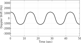 Figure G.3-1: Doppler shift trajectory for scenario 1-NR350 (15 kHz SCS)
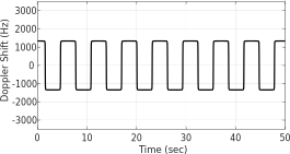 Figure G.3-2: Doppler shift trajectory for scenario 3-NR350 (15 kHz SCS)
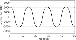 Figure G.3-3: Doppler shift trajectory for scenario 1-NR350 (30 kHz SCS)
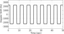 Figure G.3-4: Doppler shift trajectory for scenario 3-NR350 (30 kHz SCS)
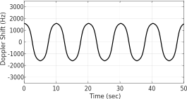 Figure G.3-5: Doppler shift trajectory for scenario 1-NR500 (15 kHz SCS)
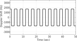 Figure G.3-6: Doppler shift trajectory for scenario 3-NR500 (15 kHz SCS)
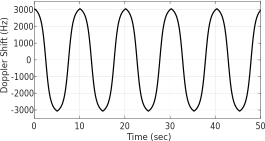 Figure G.3-7: Doppler shift trajectory for scenario 1-NR500 (30 kHz SCS)
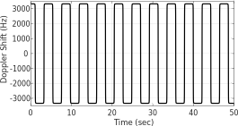 Figure G.3-8: Doppler shift trajectory for scenario 3-NR500 (30 kHz SCS)
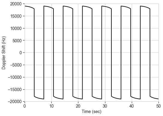 Figure G.3-9: Doppler shift trajectory for scenario 4-BI-NR350, FR2 (120 kHz SCS)
G.4 Moving propagation conditionsFigure G.4-1 illustrates the moving propagation conditions for the test of the UL timing adjustment performance. The time difference between the reference timing and the first tap is according Equation (G.4-1). The timing difference between moving UE and stationary UE is equal to Δτ - ( T A 31)1664 T c for 15kHz SCS, Δτ - ( T A 31)1632 T c for 30kHz SCS and Δτ - ( T A 31)168 T c for 120kHz SCS. The relative timing among all taps is fixed. The parameters for the moving propagation conditions are shown in Table G.4-1.
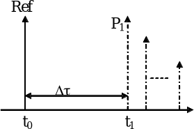 Figure G.4-1: Moving propagation conditions
| Parameter | Scenario X | Scenario Y | Scenario Z |
|---|---|---|---|
| Channel model | Stationary UE: AWGN Moving UE: TDLC300-400 | Stationary UE: AWGN Moving UE: AWGN | Stationary UE: AWGN Moving UE: AWGN |
| UE speed | 120 km/h | 350 km/h | 500 km/h |
| CP length | Normal | Normal | Normal |
| A | 15 kHz: 10 s 30 kHz: 5 s | 15 kHz: 10 s 30 kHz: 5 s 120 kHz: 1.25 s | 15 kHz: 10 s 30 kHz: 5 s |
| | 15 kHz: 0.04 s -1 30 kHz: 0.08 s -1 | 15 kHz: 0.13 s -1 30 kHz: 0.26 s -1 120 kHz: 1.04 s -1 | 15 kHz: 0.18 s -1 30 kHz: 0.36 s -1 |
| NOTE 1: Doppler shift is not taken into account in UL TA scenario Y and Z. |
Annex H (informative):
Change history
| Change history | |||||||
|---|---|---|---|---|---|---|---|
| Date | Meeting | TDoc | CR | Rev | Cat | Subject/Comment | New version |
| 2017-05 | RAN4#83 | R4-1704619 | Specification skeleton | 0.0.1 | |||
| 2017-05 | RAN4#83 | R4-1705332 | Specification skeleton (revised) | 0.0.2 | |||
| 2017-05 | RAN4#83 | R4-1706228 | Specification skeleton (revised) | 0.0.3 | |||
| 2017-07 | RAN4-NR AH #2 | R4-1706983 | Agreed Text Proposal in RAN4 NR AH #2: R4-1706955 , “TP to TS 38.104: BS classification for NR BS” | 0.1.0 | |||
| 2018-08 | RAN4#84 | R4-1709212 | Agreed Text Proposal in RAN4 #84: R4-1708872 , “TP to TS 38.104 BS transmitter transient period” | 0.2.0 | |||
| 2018-10 | RAN4#84bis | R4-1711970 | Agreed Text Proposal in RAN4 #84bis: R4-1710199 , “TP for TS 38.104: out of band blocking (10.4)” R4-1710587 , “TP for TS 38.104: Relationship with other core specifications (4.1)” R4-1710588 , “TP for TS 38.104: Relationship between minimum requirements and test requirements (4.2)” R4-1710589 , “TP for TS 38.104: Regional requirements (4.5)” R4-1710591 , “TP for TS 38.104: Conducted transmitter characteristics (general) (6.1)” R4-1710593 , “TP for TS 38.104: Operating band unwanted emissions (conducted) (6.6.4)” R4-1710594 , “TP for TS 38.104: Conducted receiver characteristics (General) (7.1)” R4-1710595 , “TP for TS 38.104: Radiated transmitter characteristics (General) (9.1)” R4-1710598 , “TP for TS 38.104: Radiated receiver characteristics (General) (10.1)” R4-1711325 , “TP to TS38.104: OTA Output power dynamics (9.4)” R4-1711363 , “TP to TS 38.104 - Occupied bandwidth (6.6.2)” R4-1711745 , “TP to TS 38.104 - Conducted and radiated requirement reference points (4.3)” R4-1711746 , “TP for TS 38.104: Adding applicability table to clause 4.6” R4-1711747 , “TP for TS 38.104: Operating bands and channel arrangements. (5)” R4-1711748 , “TP to TS38.104: conducted NR BS output power (6.2)” R4-1711750 , “TP for TS 38.104: Transmit ON/OFF power (6.4)” R4-1711753 , “TP for TS 38.104: Time alignment error requirements (6.5)” R4-1711754 , “TP for TS 38.104: Unwanted emissions, General (Conducted) (6.6.1)” R4-1711755 , “TP to TS 38.104: Occupied bandwidth for FR1 and FR2 NR BS (9.7)” R4-1711756 , “TP to TS 38.104: Transmitter spurious emissions (conducted) (6.6.5)” R4-1711757 , “TP for TS 38.104:Conducted BS transmitter intermodulation for FR1 (section 6.7)” R4-1711758 , “TP to TS 38.104: Reference Sensitivity (conducted) (7.2)” R4-1711759 , “TP to TS 38.104: NR BS conducted ACLR requirement in FR1 (6.6.3)” R4-1711760 , “TP to TS38.104: conducted NR BS receiver spurious emissions (7.6)” R4-1711761 , “TP to TS38.104: Radiated NR BS transmit power; FR1 (9.2)” R4-1711762 , “TP to TS38.104: OTA base station output power, FR1 (9.3)” R4-1711763 , “TP for TS 38.104: OTA Transmit ON/OFF power (9.5)” R4-1711764 , “TP to TS 38.104 - OTA ACLR” R4-1711765 , “TP for TS 38.104: OTA Operating band unwanted emissions and Spectrum emissions mask (9.7.4)” R4-1711766 , “TP for TS 38.104: OTA Spurious emission (9.7.5)” R4-1711767 , “TP for TS 38.104: Adding specification text for OTA TX IMD requirement in clause 9.8” R4-1711768 , “TP to TS 38.104: OTA Sensitivity (10.2)” R4-1711771 , “TP to TS38.104: OTA receiver spurious emissions, FR1 (10.7)” R4-1711772 , “TP to TS 38.104: Receiver Intermodulation (10.8)” R4-1711811 , “TP to TS 38.104: NR BS conducted in-band selectivity and blocking requirements in FR1 (7.4)” R4-1711950 , “TP to TS 38.104: Modulation Quality Skeleton (6.5)” R4-1711951 , “TP to TS38.104: frequency error for FR1 NR BS (6.5&9.6)” R4-1711952 , “TP to TS 38.104: OTA reference sensitivity (10.3)” | 0.3.0 | |||
| 2017-11 | RAN4#84bis | R4-1711971 | Alignment of structure, terminology, and definitions between clauses. | 0.4.0 | |||
| 2017-12 | RAN4#85 | R4-1714544 | Agreed Text Proposal in RAN4 #85: R4-1712614 , “TP to TS 38.104 - OTA sensitivity (10.2)” R4-1712648 , “TP to TS 38.104: corrections for the applicability of “BS type” and “requirement set” definitions” R4-1712964 , “TP for TS 38.104: out of band blocking (7.5)” R4-1713631 , “TP to 38.104 on introduction of n71” R4-1713632 , “TP to 38.104, clause 4.7 (Requirements for contiguous and non-contiguous spectrum)” R4-1713633 , “TP to 38.104, clause 4.8 (Requirements for BS capable of multi-band operation)” R4-1713634 , “TP to 38.104, clause 6.6.4.2.6 (basic limits for additional requirements for operating band unwanted emissions)” R4-1714116 , “TP to TS 38.104: Revision of the TRP definition” R4-1714117 , “TP to TS 38.104: Radiated NR BS transmit power; 2-O (9.2.3)” R4-1714121 , “TP to TS 38.104: OTA Output power dynamics (9.4)” R4-1714125 , “TP to TS 38.104 v0.4.0: OTA TDD Off power” R4-1714127 , “TP for TS 38.104: OTA frequency error (9.6.1)” R4-1714129 , “TP to TS 38.104: NR BS conducted CACLR requirements in FR1 (6.6.3)” R4-1714134 , “TP to TS 38.104v0.4.0: Absolute levels for FR2 ACLR absolute levels for NR BS” R4-1714136 , “TP for TS 38.104: Update of OTA TX IM requirement for sub-clause 4.9 and sub-clause 9.8” R4-1714141 , “TP to TS 38.104: Reference Sensitivity (conducted) (7.2)” R4-1714142 , “TP to TS 38.104: NR BS FRCs for receiver requirements” R4-1714150 , “TP to TS 38.104 - OTA out of band blocking FR1 (10.6)” R4-1714306 , “TP for TS 38.104: Adding of TRP in terminology in clause 3” R4-1714307 , “TP to TS 38.104 - Conducted and radiated requirement reference points (4.3)” R4-1714308 , “TP for TS 38.104: Base station classes (4.4)” R4-1714310 , “TP to TS 38.104: Directional and TRP requirements identification (directional vs. TRP)” R4-1714312 , “TP for TS 38.104: Update of applicability table in sub-clause 4.6” R4-1714313 , “TP to TS 38.104: Operating bands (5.1-5.3)” R4-1714315, “TP to TS38.104: frequency error for NR BS (6.5&9.6)” R4-1714316 , “TP for TS 38.104: Adding text for clause 6.5.2 Modulation quality” R4-1714317 , “TP to TS 38.104: Dynamic Range for FR1 (conducted)” R4-1714318 , “TP to TS38.104: ICS requirement (7.8&10.9)” R4-1714319 , “TP for TS 38.104: Adding text for clause 9.6.4 Modulation quality” R4-1714320 , “TP for TS 38.104: OTA Spurious emission (9.7.5)” R4-1714321 , “TP for TS 38.104: OTA Dynamic range (10.4)” R4-1714390 , “TP to TS 38.104: FR2 RX IM OTA, 10.8.3” R4-1714428 , “TP to TS 38.104 v0.4.0: Time alignment for CA” R4-1714430 , “TP to TS 38.104: Transmitter spurious emissions (conducted) (6.6.5)” R4-1714432 , “TP to TS 38.104: Output Power Dynamics for FR1 (conducted)” R4-1714433 , “TP to TS 38.104: OTA Rx spurious emissions for BS type O 2 (10.7.3)” R4-1714435 , “TP to TS 38.104: FR2 REFSENS” R4-1714437 , “TP for TS 38.104: Conducted Adjacent Channel Leakage Power Ratio (ACLR) (6.6.3)” R4-1714439 , “TP for TS 38.104: Receiver spurious emission (7.6)” R4-1714476 , “TP to TR 38.104: Channel arrangement (5.4)” R4-1714493 , “TP for TS 38.104: Operating band unwanted emissions (6.6.4)” R4-1714515 , “TP for TS 38.104: OTA Out-of-band emissions (9.7.4)” R4-1714517 , “TP to TS 38.104: OTA base station output power, 2-O (9.3.3)” R4-1714518 , “TP to TS 38.104: ACS and blocking update” R4-1714520 , “Draft TP to TS 38.104: OTA In-band selectivity and blocking (10.5)” R4-1714525 , “TP to TS 38.104: FR1 RX IM conducted 7.7” R4-1714526 , “TP to TS 38.104: FR1 RX IM OTA 10.8.2” | 0.5.0 | |||
| 2017-12 | RAN#78 | RP-172268 | Presented to TSG RAN for approval. | 1.0.0 | |||
| 2017-12 | RAN#78 | Approved by plenary – Rel-15 spec under change control | 15.0.0 | ||||
| 2018-03 | RAN#79 | RP-180264 | 0004 | F | TS 38.104 Combined updates (NSA) from RAN4 #86 and AH-1801 | 15.1.0 | |
| 2018-06 | RAN#80 | RP-181076 | 0005 | F | TS 38.104 Combined updates (NSA) from RAN4 #86bis and RAN4 #87 | 15.2.0 | |
| 2018-09 | RAN#81 | RP-181896 | 0008 | F | TS 38.104 Combined updates from RAN4 #88 | 15.3.0 | |
| 2018-12 | RAN#82 | RP-182837 | 0016 | 1 | F | CR to TS 38.104 on Combined updates from RAN4 #88bis and #89 (including 7.5 kHz carrier shift in UL for remaining bands) | 15.4.0 |
| 2018-12 | RAN#82 | RP-182362 | 0017 | B | CR to 38.104 on Combined CRs for BS Demodulation performance | 15.4.0 | |
| 2019-03 | RAN#83 | RP-190403 | 0019 | F | CR to TS 38.104 on Combined updates from RAN4 #90 This document combines the proposed changes in the following Draft CRs from RAN4 #90: - R4-1900284, “Draft CR on NR PUCCH format2 performance requirements for TS 38.104” - R4-1900763, “Draft CR to TS 38.104: Update of performance requirement numbers for DFT-s-OFDM based PUSCH” - R4-1900876, “Draft CR to TS 38.104: On RX spurious emissions requirement” - R4-1900968, “Draft CR for 38.104: Performance requirements for NR PUCCH format 1” - R4-1901329, “Draft CR to 38.104: Annex C.6 correction” - R4-1901330, “Draft CR to 38.104: Abbreviations addition” - R4-1901387, “Draft CR to TS 38.104 BS demodulation PUCCH format 0 requirements” - R4-1901474, “Draft CR to TS 38.104: Corrections on transmitter co-existence and co-location requirements” - R4-1901483, “Draft CR to TS 38.104: Corrections on general intermodulation requirement” - R4-1902239, “Draft CR to TS 38.104: Addition of missing EIRP/EIS definitions in terminology in clause 3.1” - R4-1902241, “Draft CR to 38.104; clarification of BS power limits” - R4-1902245, “Draft CR to 38.104: Correction to FR2 OTA Interfering signal mean power units” - R4-1902246, “Draft CR to 38.104; Correction to definition of OTA reference sensitivity” - R4-1902260, “draft CR to TS 38.104 - update emissions scaling” - R4-1902338, “Draft CR: Update on FR1 range extension for TS38.104” - R4-1902389, “draftCR for 38.104 on PUSCH requirements with CP-OFDM and FR1” - R4-1902394, “Draft CR to TS 38.104 – PUSCH requirements with CP-OFDM for FR2” - R4-1902396, “CR: Updates to PUCCH formats 3 and 4 performance requirements in TS 38.104” - R4-1902444, “Draft CR to TS 38.104: Editorial CR for BS demodulation requirements” - R4-1902561, “Draft CR for updating PRACH performance requirements in TS38.104” - R4-1902571, “Corrections to 38.104 Delay profile calculation” - R4-1902642, “Draft CR to TS 38.104: Correction on multi-band operation related requirements” | 15.5.0 | |
| 2019-06 | RAN#84 | RP-191240 | 0029 | F | CR to TS 38.104 Combined updates from RAN4 #90bis and RAN4#91 From RAN4 #90bis: - R4-1903105, “Draft CR to TS 38.104: Corrections on terminologies and editorial errors” - R4-1903319, “Draft CR to TS 38.104: removal of unused definition: “minimum EIRP level under extreme condition”” - R4-1903320, “Draft CR to TS 38.104: OSDD information correction” - R4-1903457, “Draft CR to TS 38.104: Removal of FFS for FR2 TDD OFF power level requirement in clause 9.5” - R4-1903499, “Draft CR to 38.104: Correction to unwanted emissions mask for bands n7 and n38” - R4-1903836, “Draft CR to TS 38.104: Correction on description on multi-band operation in section 4.8” - R4-1904024, “Draft CR to TS 38.104 Applicability rules for BS demodulation” - R4-1904234, “draftCR: Correlation matrix for 8Rx in TS 38.104” - R4-1904723, “Draft CR to TS 38.104: Update of performance requirements for DFT-s-OFDM based PUSCH” - R4-1904726, “draftCR for 38.104 on PUSCH requirements with CP-OFDM and FR1” - R4-1904729, “Draft CR on PRACH performance requirements in TS38.104” - R4-1904734, “Draft CR on TS 38.104 Performance requirement for PUCCH format 1” - R4-1904735, “Draft CR on NR PUCCH format2 performance requirements for TS 38.104” - R4-1904739, “Draft CR to TS 38.104 BS demodulation PUCCH format 0 requirements” - R4-1904745, “draftCR: Updates to PUCCH formats 3 and 4 performance requirements in TS 38.104” - R4-1904799, “Draft CR to TS 38.104: FRC update for PUSCH FR1 mapping type B and FR2 DMRS 1+1” - R4-1904816, “Draft CR : Clarification on step 5 and step 6 for delay profiles calculation (38.104)” - R4-1904842, “Draft CR to TS 38.104 BS demodulation CP-OFDM PUSCH FR2 requirements” - R4-1905126, “draft CR to 38.104 for TAE requirements” - R4-1905139, “draft CR to TS 38.104 on EVM measurement (Annex B and C)” - R4-1905140, “Draft CR: editorial correction on FR1 spurious emission requirement in TS38.104” - R4-1905143, “Draft CR for TS 38.104: Addition of NOTE for transmitter intermodulation requirements in certain regions” - R4-1905144, “Draft CR to TS 38.104: FRC reference corrections for the Rx requirements” - R4-1905145, “Draft CR to TS 38.104: Clarification on application of interfering signal offsets for ACS, blocking and intermodulation requirements” - R4-1905148, “Draft CR to TS 38.104: Corrections on out-of-band blocking requirement” From RAN4 #91: - R4-1906002, “Draft CR to 38.104: Subclause 6.7 and 9.8 transmitter intermodulation – correction of interfering signal type” - R4-1906096, “Draft CR to 38.104: Correction of frequency range for OTA spurious emissions” - R4-1906311, “Draft CR to 38.104: Correction on FRC (Annex A)” - R4-1906346, “Removal of n65 in Rel-15 38.104” - R4-1906915, “Draft CR to TS 38.104: Clarification on application of interfering signal offsets for OTA ACS, blocking and intermodulation requirements” - R4-1906918, “Draft CR to TS 38.104: Clarification on type of interfering signal for ACS, in-band blocking and ICS requirements” - R4-1907110, “Draft CR to TS 38.104: correction of the fundamental frequency limit of 2.55GHz for the spurious emissions” - R4-1907246, “Draft CR to TS 38.104: Update of performance requirements for DFT-s-OFDM based PUSCH” - R4-1907249, “Draft CR to TS 38.104: Correction on the terminology in PUSCH FRC tables” - R4-1907252, “Draft CR to TS38.104: Updates of PRACH performance requirements” - R4-1907255, “Draft CR on NR PUCCH format2 performance requirements for TS 38.104” - R4-1907258, “Draft CR on NR UCI on PUSCH performance requirements for TS 38.104” - R4-1907261, “draftCR: Updates to PUCCH formats 3 and 4 performance requirements in TS 38.104” - R4-1907266, “Draft CR on TS 38.104 Performance requirement for PUCCH format 1” - R4-1907267, “Draft CR on TS 38.104 Performance requirement for multi-slot PUCCH format 1” - R4-1907272, “Draft CR to TS 38.104 BS demodulation PUCCH format 0 requirements” - R4-1907275, “Draft CR to TS 38.104 BS demodulation CP-OFDM PUSCH FR2 requirements” - R4-1907277, “draftCR for 38.104 on PUSCH requirements with CP-OFDM and FR1” - R4-1907629, “Draft CR to 38.104: Term “reference signal” replacing by term “ideal signal” in EVM context” - R4-1907634, “Draft CR to 38.104: corrections to the EVM annex” - R4-1907659, “Draft CR to TS 38.104 on Spurious emission Category B in FR2” - R4-1907661, “Draft CR to 38.104 Definition of contiguous transmission bandwidth” - R4-1907662, “Draft CR to 38.104: BS TAE requirements” - R4-1907664, “Draft CR to 38.104: Clarification of interferer RB frequency for narrowband blocking” - R4-1907672, “Draft CR for TS 38.104: Correction on EVM” - R4-1907689, “Correction to CA carrier spacing” | 15.6.0 | |
| 2019-06 | RAN#84 | RP-191252 | 0024 | 1 | B | CR to TS38.104 to introducing spectrum sharing on band n41 | 16.0.0 |
| 2019-06 | RAN#84 | RP-191242 | 0025 | B | Introduction of band n14 - CR to TS 38.104 | 16.0.0 | |
| 2019-06 | RAN#84 | RP-191246 | 0026 | B | Introduction of band n30 - CR to TS 38.104 | 16.0.0 | |
| 2019-06 | RAN#84 | RP-191244 | 0028 | B | introduce n18 into TS38.104 | 16.0.0 | |
| 2019-06 | RAN#84 | RP-191250 | 0030 | 1 | B | n65 introduction to 38.104 | 16.0.0 |
| 2019-06 | RAN#84 | RP-191251 | 0031 | B | Addition channel bandwidth of 30MHz for n50 in TS 38.104 | 16.0.0 | |
| 2019-06 | RAN#84 | RP-191248 | 0032 | B | CR to 38.104: Introduction of n48 | 16.0.0 | |
| 2019-09 | RAN#85 | RP-192049 | 0034 | A | CR to T 38.104: Implementation of endorsed draft CRs from RAN4#92 (Rel-16) (Mirrors changes in R4-1908440 for Rel-15 TS 38.104) - R4-1907940, “Draft CR to TS 38.104: Correction on the terminology in FRC tables in A.1 and A.2” - R4-1908307, “Draft CR to TS 38.104: Clarification on application of OTA receiver requirements for BS supporting polarization” - R4-1908387, “Draft CR for TS38.104: editorial correction for reference meausrement channel” - R4-1908619, “Draft CR to TS38.104: Correction on interferer frequency offset values for ACS” - R4-1908629, “Draft CR to TS38.104: Corrections on EVM window length (Annex B.5.2, C.5.2)” - R4-1908774, “DraftCR to 38.104: Editorial Corrections to redudant units in clause 10.8.3” - R4-1908805, “Draft CR to 38.104: Limits in FCC title 47 for OTA operating band unwanted emissions (9.7)” - R4-1909270, “Draft CR to TS 38.104: Receiver spurious emissions frequency correction” - R4-1909309, “DraftCR to TS 38.104: text corrections, Rel-15” - R4-1909310, “DraftCR to 38.104: correction of TAB connectors mapping to TAB connector TX min cell group, Rel-15” - R4-1909416, “draft CR 38.104 - correct reference to annex F” - R4-1910066, “Draft CR to TS 38.104: Update of performance requirements for DFT-s-OFDM based PUSCH” - R4-1910069, “Draft CR on NR PUCCH format2 performance requirements for TS 38.104” - R4-1910072, “Draft CR on NR UCI on PUSCH performance requirements for TS 38.104” - R4-1910075, “draftCR for 38.104 on PUSCH requirements with CP-OFDM and FR1” - R4-1910078, “Draft CR to TS38.104: Updates to NR PRACH performance requirements” - R4-1910081, “Draft CR to TS 38.104 BS demodulation PUCCH format 0 requirements” - R4-1910084, “Draft CR to TS 38.104 BS demodulation CP-OFDM PUSCH FR2 requirements” - R4-1910088, “Draft CR for 38.104: Performance requirements for NR PUCCH format 1” - R4-1910089, “Draft CR for 38.104: Performance requirements for NR multi-slot PUCCH” - R4-1910094, “draftCR: Updates to PUCCH formats 3 and 4 performance requirements in TS 38.104” - R4-1910431, “Corrections to EVM calculations in 38.141-1 annex B” - R4-1910462, “Draft CR to 38.104: Correction on regional requirements (4.5)” - R4-1910493, “Draft CR to TS 38.104 correction to Annex C.7” - R4-1910606, “Draft CR for TS 38.104: Channel spacing for adjacent NR carriers” | 16.1.0 | |
| 2019-09 | RAN#85 | RP-192032 | 0035 | 1 | B | CR to introduce 30MHz bandwidth of n41 to TS 38.104 | 16.1.0 |
| 2019-09 | RAN#85 | RP-192029 | 0036 | B | CR on Introduction and Protection of SUL band n89 into TS 38.104 | 16.1.0 | |
| 2019-09 | RAN#85 | RP-192031 | 0037 | B | CR for TS 38.104: adding wider channel bandwidths in Band n7 | 16.1.0 | |
| 2019-09 | RAN#85 | RP-192034 | 0039 | B | n29 introduction to 38.104 | 16.1.0 | |
| 2019-12 | RAN#86 | RP-192999 | 0049 | 1 | A | CR to TS 38.104: Update of performance requirements for DFT-s-OFDM based PUSCH (Rel-16) | 16.2.0 |
| 2019-12 | RAN#86 | RP-193013 | 0050 | 1 | B | Introduction of 2010-2025MHz SUL band into Rel-16 TS 38.104 | 16.2.0 |
| 2019-12 | RAN#86 | RP-193034 | 0055 | A | Sync raster to SSB resource element mapping | 16.2.0 | |
| 2019-12 | RAN#86 | RP-192999 | 0057 | A | CR on correction of NR PUCCH format2 performance requirements (Rel-16) for TS 38.104 | 16.2.0 | |
| 2019-12 | RAN#86 | RP-192999 | 0059 | 1 | A | CR on correction of NR UCI on PUSCH performance requirements (Rel-16) for TS 38.104 | 16.2.0 |
| 2019-12 | RAN#86 | RP-192999 | 0061 | A | CR on correction on FRC table for FR1 PUSCH performance requirements (Rel-16) for TS 38.104 | 16.2.0 | |
| 2019-12 | RAN#86 | RP-192999 | 0063 | 1 | A | CR for 38.104 on PUSCH requirements with CP-OFDM and FR1 | 16.2.0 |
| 2019-12 | RAN#86 | RP-193034 | 0065 | A | CR for TS38.104: Corrections on channel bandwdith for band n34 | 16.2.0 | |
| 2019-12 | RAN#86 | RP-193035 | 0067 | A | CR to TS38.104: Editorial corrections | 16.2.0 | |
| 2019-12 | RAN#86 | RP-193035 | 0070 | 1 | A | CR to 38.104 on Editorial corrections (Rel-16) | 16.2.0 |
| 2019-12 | RAN#86 | RP-193034 | 0074 | A | CR to 38.104 on Receiver spurious emission requirements | 16.2.0 | |
| 2019-12 | RAN#86 | RP-193021 | 0075 | 1 | F | CR to remove square brackets for n90 in TS38.104 | 16.2.0 |
| 2019-12 | RAN#86 | RP-192999 | 0077 | A | Updates to PRACH requirements in TS 38.104 for Rel-16 | 16.2.0 | |
| 2019-12 | RAN#86 | RP-193034 | 0081 | A | CR to TS 38.104: Correction on interference level of receiver dynamic range requirement | 16.2.0 | |
| 2019-12 | RAN#86 | RP-193034 | 0083 | A | CR to TS 38.104: Finalization of interfering RB centre frequency offsets in receiver narrowband blocking requirement | 16.2.0 | |
| 2019-12 | RAN#86 | RP-193034 | 0085 | A | CR to TR 38.104: Correction of table reference of interfering signal for ACS requirement | 16.2.0 | |
| 2019-12 | RAN#86 | RP-193034 | 0087 | A | CR to TS 38.104: Correction on interfering signal frequency offsets for receiver intermodulation requirements | 16.2.0 | |
| 2019-12 | RAN#86 | RP-193034 | 0089 | A | CR to TS 38.104 on corrections to channel raster entries for NR band (Rel-16) | 16.2.0 | |
| 2019-12 | RAN#86 | RP-193035 | 0097 | A | CR to TS38.104: further updates on the abbreviations (section 3.3)-R16 | 16.2.0 | |
| 2019-12 | RAN#86 | RP-193023 | 0098 | 1 | B | CR to TS 38.104 - NB-IoT introduction | 16.2.0 |
| 2019-12 | RAN#86 | RP-192999 | 0100 | F | CR to TS 38.104 BS demodulation PUCCH format 0 requirements | 16.2.0 | |
| 2019-12 | RAN#86 | RP-192999 | 0102 | 1 | F | CR to TS 38.104 BS demodulation CP-OFDM PUSCH FR2 requirements | 16.2.0 |
| 2019-12 | RAN#86 | RP-193017 | 0103 | B | CR to 38.104 - Band n75 - wider CBW | 16.2.0 | |
| 2019-12 | RAN#86 | RP-193018 | 0105 | B | CR for TS 38.104: adding wider channel bandwidths in Band n77/n78 | 16.2.0 | |
| 2019-12 | RAN#86 | RP-193016 | 0106 | B | CR for TS 38.104: Addition channel bandwidth of 40MHz for n38 | 16.2.0 | |
| 2019-12 | RAN#86 | RP-193035 | 0108 | A | CR to 38.104: Correction on FR2 Category B OBUE mask | 16.2.0 | |
| 2019-12 | RAN#86 | RP-193002 | 0110 | A | CR Frame averaging for EVM Annex B and C in TS 38.104 | 16.2.0 | |
| 2019-12 | RAN#86 | RP-193035 | 0112 | A | CR to TS 38.104: OTA TAE correction, Rel-16 | 16.2.0 | |
| 2019-12 | RAN#86 | RP-193035 | 0114 | A | CR to TS 38.104: MR BS class terminology correction, Rel-16 | 16.2.0 | |
| 2019-12 | RAN#86 | RP-192999 | 0116 | 1 | F | CR: Updates for PUCCH formats 3 and 4 performance requirements in TS 38.104 (Rel-16) | 16.2.0 |
| 2019-12 | RAN#86 | RP-193035 | 0118 | A | Correction of limit for TX spurios BS type 1-H | 16.2.0 | |
| 2019-12 | RAN#86 | RP-192999 | 0119 | A | CR for 38.104: Performance requirements for NR PUCCH format 1 | 16.2.0 | |
| 2019-12 | RAN#86 | RP-192999 | 0120 | A | CR for 38.104: Performance requirements for NR multi-slot PUCCH | 16.2.0 | |
| 2019-12 | RAN#86 | RP-193035 | 0122 | A | CR to TS 38.104: Editorial corrections | 16.2.0 | |
| 2019-12 | RAN#86 | RP-193035 | 0124 | A | CR to TS 38.104: Clarification for the number of interfering signals | 16.2.0 | |
| 2020-03 | RAN#87 | RP-200381 | 0126 | B | Introduction of n26 | 16.3.0 | |
| 2020-03 | RAN#87 | RP-200382 | 0127 | 1 | B | Introduction of n53 | 16.3.0 |
| 2020-03 | RAN#87 | RP-200384 | 0131 | B | Introducing new channel bandwidth for band n28 | 16.3.0 | |
| 2020-03 | RAN#87 | RP-200410 | 0132 | F | CR to TS 38.104: Corrections on NB-IoT operation in NR channel bandwidth | 16.3.0 | |
| 2020-03 | RAN#87 | RP-200398 | 0134 | 1 | A | CR to TS 38.104: Corrections on rated carrier output power symbols | 16.3.0 |
| 2020-03 | RAN#87 | RP-200379 | 0136 | 1 | C | CR for 38.104: new FRC tables for FR2 PUSCH 2T2R MCS12 | 16.3.0 |
| 2020-03 | RAN#87 | RP-200407 | 0137 | 2 | B | CR for 38.104: introduction of UL timing adjustment | 16.3.0 |
| 2020-03 | RAN#87 | RP-200407 | 0138 | 2 | B | CR for 38.104: Appendix for UL timing adjustment | 16.3.0 |
| 2020-03 | RAN#87 | RP-200386 | 0139 | B | CR for TS 38.104: adding wider channel bandwidths for n66 | 16.3.0 | |
| 2020-03 | RAN#87 | RP-200398 | 0142 | A | CR to TS 38.104: Regional requirements | 16.3.0 | |
| 2020-03 | RAN#87 | RP-200392 | 0143 | F | Maintenance on the BS BW for n92 and n94 | 16.3.0 | |
| 2020-03 | RAN#87 | RP-200398 | 0145 | A | IntraSlot frequency hopping applicability in the one OFDM symbol test case | 16.3.0 | |
| 2020-03 | RAN#87 | RP-200383 | 0146 | 1 | B | CR to 38.104 Band n1 - wider CBW - Additional Channel BW | 16.3.0 |
| 2020-03 | RAN#87 | RP-200385 | 0148 | B | CR to 38.104 Band n38 - wider CBW - Additional Channel BW | 16.3.0 | |
| 2020-03 | RAN#87 | RP-200398 | 0149 | A | CR to TS 38.104 editorial correction R16 catA | 16.3.0 | |
| 2020-03 | RAN#87 | RP-200407 | 0156 | 1 | B | CR for TS 38.104: Introduction of PRACH demodulation requirements for NR HST | 16.3.0 |
| 2020-03 | RAN#87 | RP-200407 | 0157 | 2 | B | CR for 38.104: HST PUSCH demodulation requirements introduction | 16.3.0 |
| 2020-03 | RAN#87 | RP-200407 | 0158 | 2 | B | CR for 38.104: HST PUSCH demodulation Annex including both FRC and channel model | 16.3.0 |
| 2020-03 | RAN#87 | RP-200379 | 0159 | 1 | C | CR for 38.104: Performance requirements for FR2 PUSCH 2T2R 16QAM | 16.3.0 |
| 2020-06 | RAN#88 | RP-200986 | 0164 | A | CR for 38.104: Performance requirements clarification of PUSCH BS Type O-2 PT-RS configuration for MCS 2 | 16.4.0 | |
| 2020-06 | RAN#88 | RP-201043 | 0167 | F | CR for 38.104: Performance requirements for FR2 PUSCH 2T2R 16QAM | 16.4.0 | |
| 2020-06 | RAN#88 | RP-200986 | 0176 | A | CR to TS 38.104: Correction to out-of-band blocking requirements in subclause 7.5 and subclause 10.6 | 16.4.0 | |
| 2020-06 | RAN#88 | RP-200986 | 0178 | A | CR to TS 38.104: Correction on the CA nominal channel spacing | 16.4.0 | |
| 2020-06 | RAN#88 | RP-200986 | 0180 | A | 30k SSB SCS for n50 | 16.4.0 | |
| 2020-06 | RAN#88 | RP-200986 | 0182 | A | Addition of 30k SSB SCS for Band n38 | 16.4.0 | |
| 2020-06 | RAN#88 | RP-200972 | 0185 | B | CR to TS 38.104: Introduction of FR2 DL 256QAM | 16.4.0 | |
| 2020-06 | RAN#88 | RP-200977 | 0190 | B | CR for TS 38.104: adding 50 MHz CBW for n1 | 16.4.0 | |
| 2020-06 | RAN#88 | RP-200986 | 0195 | A | CR to 38.104: Adding missing clause on Radiated Performance requirements for multi-slot PUCCH (11.3.1) | 16.4.0 | |
| 2020-06 | RAN#88 | RP-200980 | 0198 | B | CR to TS 38.104 - Add 40 MHz CBW in band n3 | 16.4.0 | |
| 2020-06 | RAN#88 | RP-200982 | 0199 | B | CR to TS 38.104 - Add 50 MHz CBW in band n65 | 16.4.0 | |
| 2020-06 | RAN#88 | RP-200986 | 0209 | A | CR to 38.104 on Receiver spurious emissions exclusion band (Rel-16) | 16.4.0 | |
| 2020-06 | RAN#88 | RP-200986 | 0211 | A | CR to 38.104 on EESS protection for bands n257 and n258 (Rel-16) | 16.4.0 | |
| 2020-06 | RAN#88 | RP-200986 | 0213 | A | TS38.104 draft CR on 30KHz SSB SCS for n40 (Rel-16) | 16.4.0 | |
| 2020-06 | RAN#88 | RP-200986 | 0207 | 1 | A | CR to 38.104 on Removal of brackets and TBD (Rel-16) | 16.4.0 |
| 2020-06 | RAN#88 | RP-200975 | 0165 | 1 | B | CR for 38.104: HST PUSCH demodulation requirements | 16.4.0 |
| 2020-06 | RAN#88 | RP-200975 | 0166 | 1 | B | CR for 38.104: HST PUSCH demodulation FRC and channel model annexes | 16.4.0 |
| 2020-06 | RAN#88 | RP-200975 | 0186 | 1 | F | CR for 38.104 Introduction of PRACH demodulation requirements for NR HST | 16.4.0 |
| 2020-06 | RAN#88 | RP-200975 | 0187 | 1 | B | CR for 38.104: Performance requirements for UL timing adjustment | 16.4.0 |
| 2020-06 | RAN#88 | RP-201043 | 0168 | 1 | B | CR for TS 38.104: Introduce PUSCH performance requirements at 30% throughput test point | 16.4.0 |
| 2020-06 | RAN#88 | RP-200986 | 0172 | 1 | F | UCI multiplexed on PUSCH requirement | 16.4.0 |
| 2020-06 | RAN#88 | RP-200978 | 0205 | 1 | B | CR to 38.104 for Introduction of band n259 | 16.4.0 |
| 2020-09 | RAN#89 | RP-201497 | 0218 | 1 | B | CR for 38.104: HST PUSCH demodulation requirements | 16.5.0 |
| 2020-09 | RAN#89 | RP-201497 | 0219 | 1 | B | CR for 38.104: HST PUSCH demodulation FRC and channel model annexes | 16.5.0 |
| 2020-09 | RAN#89 | RP-201502 | 0220 | 1 | B | Introduction of LTE/NR spectrum sharing in band 48/n48 frequency range | 16.5.0 |
| 2020-09 | RAN#89 | RP-201512 | 0222 | A | CR to TS 38.104: Correction of co-location requirement in subclause 7.5.3 | 16.5.0 | |
| 2020-09 | RAN#89 | RP-201512 | 0224 | A | CR to TS38.104: Add 30k SSB SCS for Band n34 and n39 | 16.5.0 | |
| 2020-09 | RAN#89 | RP-201512 | 0227 | 1 | A | CR to TS 38.104: OTA receiver spurious requirements for EESS protection (rel-16) | 16.5.0 |
| 2020-09 | RAN#89 | RP-201499 | 0228 | F | CR for 38.104: Performance requirements for UL timing adjustment | 16.5.0 | |
| 2020-09 | RAN#89 | RP-201507 | 0229 | F | Correction to NB-IoT Bands with n26 | 16.5.0 | |
| 2020-09 | RAN#89 | RP-201512 | 0233 | 1 | A | CR to 38.104: Annex B and C clarification on equlisation calculation (B.6, C.6) | 16.5.0 |
| 2020-09 | RAN#89 | RP-202101 | 0238 | 1 | C | 7.5 kHz UL shift for LTE/NR spectrum sharing in Band 38/n38 | 16.5.0 |
| 2020-09 | RAN#89 | RP-202113 | 0239 | 1 | B | CR to TS 38.104: Introduction of NR-U into BS core specification | 16.5.0 |
| 2020-12 | RAN#90 | RP-202422 | 0242 | 1 | F | CR for 38.104: HST PUSCH demodulation requirements | 16.6.0 |
| 2020-12 | RAN#90 | RP-202416 | 0243 | 1 | B | CR for 38.104: Ultra high reliability BS demodulation requirements | 16.6.0 |
| 2020-12 | RAN#90 | RP-202416 | 0244 | 1 | B | CR for 38.104: Low latency BS demodulation requirements | 16.6.0 |
| 2020-12 | RAN#90 | RP-202415 | 0245 | 2 | B | CR to TS 38.104 BS demodulation requirements for 2-step RACH | 16.6.0 |
| 2020-12 | RAN#90 | RP-202414 | 0247 | 1 | F | CR to TS 38.104 with NR-U remaining open issues updates | 16.6.0 |
| 2020-12 | RAN#90 | RP-202415 | 0248 | 1 | B | CR on BS demodulation requirements for 2-step RACH for FR2 | 16.6.0 |
| 2020-12 | RAN#90 | RP-202416 | 0249 | 1 | B | CR to TS 38.104: Addition of BS performance requirements for URLLC PUSCH repetition Type A | 16.6.0 |
| 2020-12 | RAN#90 | RP-202422 | 0250 | 1 | B | CR for 38.104: Introduction of performance requirements for NR HST PRACH under fading channel | 16.6.0 |
| 2020-12 | RAN#90 | RP-202423 | 0257 | 1 | F | Adding FRC table description in Annex in TS38.104 v16.5.0 | 16.6.0 |
| 2020-12 | RAN#90 | RP-202488 | 0261 | A | CR to 38.104 on Category B OTA spurious emissions for and n257 | 16.6.0 | |
| 2020-12 | RAN#90 | RP-202451 | 0240 | B | Introduction of 1880-1920MHz SUL band into Rel-17 TS 38.104 | 17.0.0 | |
| 2020-12 | RAN#90 | RP-202452 | 0241 | B | Introduction of 2300-2400MHz SUL band into Rel-17 TS 38.104 | 17.0.0 | |
| 2020-12 | RAN#90 | RP-202448 | 0253 | B | CR to TS 38.104: introduction of NR band n13 | 17.0.0 | |
| 2020-12 | RAN#90 | RP-202453 | 0258 | 1 | B | Big CR to 38.104 - Additional Channel BW | 17.0.0 |
| 2020-12 | RAN#90 | RP-202456 | 0214 | 3 | B | LTE/NR spectrum sharing in Band 40/n40 | 17.0.0 |
| 2021-03 | RAN#91e | RP-210096 | 0262 | 2 | B | CR for TS 38.104 Introduction of SUL for UL of NR band n24 | 17.1.0 |
| 2021-03 | RAN#91e | RP-210078 | 0264 | A | CR for 38.104: HST PUSCH demodulation requirements | 17.1.0 | |
| 2021-03 | RAN#91e | RP-210068 | 0266 | A | CR for 38.104: Low latency FR1 BS demodulation requirements | 17.1.0 | |
| 2021-03 | RAN#91e | RP-210068 | 0268 | A | CR for 38.104: Ultra high reliability BS demodulation requirements | 17.1.0 | |
| 2021-03 | RAN#91e | RP-210068 | 0270 | A | CR on PUSCH repetition type A and PUSCH mapping type B radiated performance requirement for TS 38.104 | 17.1.0 | |
| 2021-03 | RAN#91e | RP-210117 | 0273 | A | CR to TS 38.104: Additions of regional requirements for n41 and n90 in Japan, Rel-17 | 17.1.0 | |
| 2021-03 | RAN#91e | RP-210073 | 0275 | A | CR on correction 2-step RACH performance requirements for FR2 in 38.104 (Rel-17) | 17.1.0 | |
| 2021-03 | RAN#91e | RP-210078 | 0277 | A | CR for 38.104: Cleanup for performance requirements of NR HST PRACH under | 17.1.0 | |
| 2021-03 | RAN#91e | RP-210068 | 0279 | A | CR to TS 38.104: Correction of BS performance requirements for URLLC PUSCH repetition Type A | 17.1.0 | |
| 2021-03 | RAN#91e | RP-210084 | 0282 | A | CR to TS 38.104: system parameters maintenance for NR-U | 17.1.0 | |
| 2021-03 | RAN#91e | RP-210084 | 0284 | A | CR to TS 38.104: corrections of NR-U BS Tx requirements | 17.1.0 | |
| 2021-03 | RAN#91e | RP-210084 | 0286 | A | CR to TS 38.104: corrections of NR-U BS Rx requirements | 17.1.0 | |
| 2021-03 | RAN#91e | RP-210117 | 0289 | A | CR to TS 38.104: EESS protection requirement correction | 17.1.0 | |
| 2021-03 | RAN#91e | RP-210189 | 0291 | B | Big CR to 38.104 - Additional Channel BW | 17.1.0 | |
| 2021-03 | RAN#91e | RP-210117 | 0294 | A | CR to TS38.104: Correction on the Aggregated Channel Bandwidth | 17.1.0 | |
| 2021-03 | RAN#91e | RP-210097 | 0295 | B | CR to 38.104: Introduction of n24 | 17.1.0 | |
| 2021-03 | RAN#91e | RP-210084 | 0297 | A | CR to TS 38.104 corrections to NR-U BS RF Tx requirements | 17.1.0 | |
| 2021-03 | RAN#91e | RP-210084 | 0299 | A | CR to TS 38.104 corrections to NR-U BS RF Rx requirements | 17.1.0 | |
| 2021-06 | RAN#92 | RP-211117 | 0305 | A | Correction of the channel raster of n259 for TS 38.104 | 17.2.0 | |
| 2021-06 | RAN#92 | RP-211095 | 0307 | A | CR to TS 38.104: Corrections on frequency offset symbols for spectrum emission mask for non-transmitted channels | 17.2.0 | |
| 2021-06 | RAN#92 | RP-211079 | 0310 | F | CR to TS 38.104 on BS channel bandwidth per operating band | 17.2.0 | |
| 2021-06 | RAN#92 | RP-211105 | 0314 | A | CR on correction of PUSCH repetition type A and PUSCH mapping type B radiated performance requirements for TS 38.104 | 17.2.0 | |
| 2021-06 | RAN#92 | RP-211121 | 0318 | 1 | B | CR to TS 38.104: Introduction of band n262 | 17.2.0 |
| 2021-06 | RAN#92 | RP-211115 | 0319 | B | Big CR to TS 38.104: Adding channel BW support in existing NR bands | 17.2.0 | |
| 2021-06 | RAN#92 | RP-211116 | 0320 | 1 | B | CR to TS 38.104: Introduction of band n67 | 17.2.0 |
| 2021-06 | RAN#92 | RP-211116 | 0321 | 1 | B | CR to TS 38.104: Introduction of band n85 | 17.2.0 |
| 2021-06 | RAN#92 | RP-211095 | 0323 | A | CR to 38.104 with correction of NR-U 60 MHz and 80 MHz channels | 17.2.0 | |
| 2021-06 | RAN#92 | RP-211094 | 0325 | A | Big CR for NR-U BS demodulation requirements in TS 38.104 (Rel-17) | 17.2.0 | |
| 2021-06 | RAN#92 | RP-211108 | 0329 | A | CR for 38.104: HST PUSCH demodulation requirements and spec maintenance | 17.2.0 | |
| 2021-06 | RAN#92 | RP-211108 | 0331 | A | CR for 38.104: Low latency and ultra-low BLER FR1 BS demodulation requirements | 17.2.0 | |
| 2021-06 | RAN#92 | RP-211090 | 0333 | A | CR to 38.104: In-band blocking for multi-band Base Stations | 17.2.0 | |
| 2021-09 | RAN#93 | RP-211907 | 0343 | B | Big CR to TS 38.104: Adding channel BW support in existing NR bands | 17.3.0 | |
| 2021-09 | RAN#93 | RP-211909 | 0341 | B | CR for TS 38.104: introduction of channel bandwidths 35MHz and 45MHz NOTE The CR is not implemented | 17.3.0 | |
| 2021-09 | RAN#93 | RP-211910 | 0348 | B | Introduction of the UL 7.5kHz shift for NR TDD band n34 and n39 in 38.104 R17 | 17.3.0 | |
| 2021-09 | RAN#93 | RP-211926 | 0351 | F | Big CR for TS 38.104 Maintenance Demod part (Rel-17, CAT F) | 17.3.0 | |
| 2021-09 | RAN#93 | RP-211926 | 0354 | A | Big CR for TS 38.104 Maintenance RF part (Rel-17, CAT A) | 17.3.0 | |
| 2021-12 | RAN#94 | RP-212835 | 0356 | B | Big CR to TS 38.104: Adding channel BW support in existing NR bands | 17.4.0 | |
| 2021-12 | RAN#94 | RP-212836 | 0357 | F | CR to TS 38.104 - Fix to band n85 introduction | 17.4.0 | |
| 2021-12 | RAN#94 | RP-212825 | 0355 | 2 | B | CR for TS 38.104: 1024QAM | 17.4.0 |
| 2021-12 | RAN#94 | RP-212824 | 0360 | F | Big CR for TS 38.104 Maintenance RF part (Rel-17, CAT F) | 17.4.0 | |
| 2021-12 | RAN#94 | RP-212850 | 0362 | F | Big CR for TS 38.104 Maintenance Demod part (Rel-17, CAT F) | 17.4.0 | |
| 2021-12 | RAN#94 | RP-213147 | 0363 | B | CR for TS 38.104: introduction of channel bandwidths 35MHz and 45MHz NOTE The CR is a resubmission of CR R4-2114918 of RP-211909 | 17.4.0 | |
| 2022-03 | RAN#95-e | RP-220377 | 0364 | 1 | B | CR for TS 38.104: capturing HAPS requirements | 17.5.0 |
| 2022-03 | RAN#95-e | RP-220347 | 0365 | 1 | B | CR to TS38.104 on introduction of upper 700MHz A block | 17.5.0 |
| 2022-03 | RAN#95-e | RP-220357 | 0369 | 1 | B | CR for 38.104 to introduce n102 | 17.5.0 |
| 2022-03 | RAN#95-e | RP-220361 | 0372 | B | BigCR for TS38.104: Introduction of conformance testing requirements for FR1 PUSCH 256QAM | 17.5.0 | |
| 2022-03 | RAN#95-e | RP-220334 | 0374 | F | Big CR for TS 38.104 Maintenance RF part (Rel-17, CAT F) | 17.5.0 | |
| 2022-03 | RAN#95-e | RP-220334 | 0376 | A | Big CR for TS 38.104 Maintenance Demod part (Rel-17, CAT A) | 17.5.0 | |
| 2022-03 | RAN#95-e | RP-220376 | 0378 | B | Big CR to 38.104: RMR 1900MHz band n101 introduction | 17.5.0 | |
| 2022-06 | RAN#96 | RP-221680 | 0379 | B | Big CR on FR2 HST BS demodulation requirement for TS 38.104 | 17.6.0 | |
| 2022-06 | RAN#96 | RP-221684 | 0380 | 1 | B | CR to TS 38.104 - Tx requirements: RMR 900MHz band introduction | 17.6.0 |
| 2022-06 | RAN#96 | RP-221671 | 0381 | B | Big CR to TS 38.104: Adding channel BW support in existing NR bands | 17.6.0 | |
| 2022-06 | RAN#96 | RP-221684 | 0382 | 1 | B | CR to 38.104 on introduction of n100 (system parameters) | 17.6.0 |
| 2022-06 | RAN#96 | RP-221673 | 0383 | 1 | B | CR to TS38.104 the introduction of 6425-7125MHz | 17.6.0 |
| 2022-06 | RAN#96 | RP-221676 | 0384 | B | Big CR to 38.104 for Rel-17 NR extension up to 71 GHz introduction | 17.6.0 | |
| 2022-06 | RAN#96 | RP-221684 | 0385 | B | CR to TS 38.104: RMR900 Rx requirements for band n100, Rel-17 | 17.6.0 | |
| 2022-06 | RAN#96 | RP-221676 | 0386 | B | Big CR on extending NR to 71GHz for TS 38.104 | 17.6.0 | |
| 2022-06 | RAN#96 | RP-221655 | 0389 | F | Big CR for TS 38.104 Maintenance RF part (Rel-17, CAT F) | 17.6.0 | |
| 2022-06 | RAN#96 | RP-221659 | 0391 | A | Big CR for TS 38.104 Maintenance Demod part (Rel-17, CAT A) | 17.6.0 | |
| 2022-09 | RAN#97 | RP-222038 | 0394 | 1 | F | CR to 38.104 on n100 corrections | 17.7.0 |
| 2022-09 | RAN#97 | RP-222041 | 0395 | F | Big CR on FR2 HST BS demodulation requirement for TS 38.104 | 17.7.0 | |
| 2022-09 | RAN#97 | RP-222050 | 0401 | 1 | B | CR for 38.104: Add 5 MHz channel BW for n41 | 17.7.0 |
| 2022-09 | RAN#97 | RP-222026 | 0404 | F | Big CR for TS 38.104 Maintenance RF part (Rel-17, CAT F) | 17.7.0 | |
| 2022-09 | RAN#97 | RP-222026 | 0407 | F | Big CR for TS 38.104 Maintenance Demod part (Rel-17, CAT F) | 17.7.0 | |
| 2022-09 | RAN#97 | RP-222051 | 0408 | F | Big CR to 38.104 for Rel-17 NR extension up to 71 GHz maintenance (Rel-17, CAT F) | 17.7.0 | |
| 2022-09 | RAN#97 | RP-222051 | 0410 | B | Big CR of TS38.104 on system parameter updates for FR2-2 | 17.7.0 | |
| 2022-12 | RAN#98-e | RP-223307 | 0411 | F | CR to TS 38.104 on reference to FRCs | 17.8.0 | |
| 2022-12 | RAN#98-e | RP-223307 | 0412 | F | CR to TS 38.104: Correction of guardband for FR2-2 in sub-clause 5.3.3 | 17.8.0 | |
| 2022-12 | RAN#98-e | RP-223300 | 0413 | B | Big CR for coverage enhancement performance requirements for TS38.104 | 17.8.0 | |
| 2022-12 | RAN#98-e | RP-223308 | 0414 | 1 | B | Corrections for 100MHz CBW inclusion for n46 n96 and n102 | 17.8.0 |
| 2022-12 | RAN#98-e | RP-223309 | 0415 | F | CR to TS 38.104 on tables for BS channel bandwidths | 17.8.0 | |
| 2022-12 | RAN#98-e | RP-223297 | 0419 | F | CR for TS38.104 correction on normal PUSCH requirements (Rel-17) | 17.8.0 | |
| 2022-12 | RAN#98-e | RP-223309 | 0424 | 2 | F | CR to 38.104: Spurious emission requirements, Rel-17 | 17.8.0 |
| 2022-12 | RAN#98-e | RP-223302 | 0426 | B | Big CR for TS 38.104 Demodulation requirements for Enhanced IIOT and URLLC support (Rel-17, CAT B) | 17.8.0 | |
| 2022-12 | RAN#98-e | RP-223298 | 0429 | F | CR for 38.104: define home class as one kind of LA BS | 17.8.0 | |
| 2022-12 | RAN#98-e | RP-223524 | 0432 | 1 | A | CR on R17 TS 38.104 to add channel raster exception for band n28 [n28_BS40MHz_raster] | 17.8.0 |
| Change history | |||||||
|---|---|---|---|---|---|---|---|
| Date | Meeting | TDoc | CR | Rev | Cat | Subject/Comment | New version |
| 2022-12 | RAN#98-e | RP-223315 | 0428 | B | CR to 38.104 on introduction of Band 54 | 18.0.0 | |
| 2022-12 | RAN#98-e | RP-223319 | 0433 | B | CR to TS38.104 the introduction of APT600MHz | 18.0.0 | |
| 2023-03 | RAN#99 | RP-230513 | 0435 | A | Correction of coverage enhancement BS demodulation requirement in 38.104 (R18 A) | 18.1.0 | |
| 2023-03 | RAN#99 | RP-230514 | 0437 | A | CR to TS 38.104 on table references for OTA operating band unwanted emission limits | 18.1.0 | |
| 2023-03 | RAN#99 | RP-230510 | 0439 | A | Big CR to 38.104: demodulation requirements introduction for FR2-2 | 18.1.0 | |
| 2023-03 | RAN#99 | RP-230515 | 0441 | A | CR for TS 38.104 Demodulation requirements for Enhanced IIOT and URLLC support (Rel-18, CAT A) | 18.1.0 | |
| 2023-03 | RAN#99 | RP-230535 | 0446 | 1 | B | CR to 38.104 on introduction of Band n54 | 18.1.0 |
| 2023-03 | RAN#99 | RP-230506 | 0449 | A | CR to 38.104: FRC number corrections (Rel-18) | 18.1.0 | |
| 2023-03 | RAN#99 | RP-230559 | 0450 | B | Big CR to TS 38.104: Adding channel BW support in existing NR bands | 18.1.0 | |
| 2023-03 | RAN#99 | RP-230513 | 0452 | A | CR to 38.104: BS Conformance, OBUE correction for 6G licensed band | 18.1.0 | |
| 2023-03 | RAN#99 | RP-230514 | 0460 | A | CR to TS 38.104: NR-ARFCN table reference correction for band n263, Rel-18 | 18.1.0 | |
| 2023-03 | RAN#99 | RP-230514 | 0464 | A | CR to 38.104: Correction on Rx intermodulation requirements for FR2-2 (Rel-18) | 18.1.0 | |
| 2023-06 | RAN#100 | RP-231347 | 0466 | A | Draft CR 38.104: PUSCH requirements for FR2-2 | 18.2.0 | |
| 2023-06 | RAN#100 | RP-231347 | 0468 | A | CR to TS 38.104 on corrections of table references for extending current NR operation to 71GHz | 18.2.0 | |
| 2023-06 | RAN#100 | RP-231348 | 0470 | A | CR to TS 38.104 on corrections and clarifications of operating band unwanted emission limits for band n104 | 18.2.0 | |
| 2023-06 | RAN#100 | RP-231348 | 0472 | A | CR for TR 38.104, Correction on reference of PREFSENS for in-band blocking and out-of-band blocking for band n104 | 18.2.0 | |
| 2023-06 | RAN#100 | RP-231347 | 0477 | A | CR for TS38.104 FRC tables for FR2-2 PUSCH demodulation_Rel-18 | 18.2.0 | |
| 2023-06 | RAN#100 | RP-231350 | 0479 | 1 | A | CR for TS38.104 on FRC table for PUSCH TBoMS_Rel-18 | 18.2.0 |
| 2023-06 | RAN#100 | RP-231352 | 0482 | 1 | A | CR for TS 38.104: Operating band unwanted emissions for Single RAT BS supporting multi-band operation | 18.2.0 |
| 2023-06 | RAN#100 | RP-231339 | 0485 | A | CR to TS 38.104 - Maintenance related to bands n100 and n101 | 18.2.0 | |
| 2023-06 | RAN#100 | RP-231352 | 0488 | A | CR on 38.104: Updates to FRC of PUSCH requirements(Rel-18) | 18.2.0 | |
| 2023-06 | RAN#100 | RP-231342 | 0490 | A | CR on 38.104: Updates to the test setup for the PF0 requirements with sub-slot repetition(Rel-18) | 18.2.0 | |
| 2023-06 | RAN#100 | RP-231362 | 0491 | B | CR to 38.104 on introduction of Band 106 | 18.2.0 | |
| 2023-06 | RAN#100 | RP-231356 | 0496 | A | CR to 38.104: Correction to ACLR and CACLR requirement | 18.2.0 | |
| 2023-06 | RAN#100 | RP-231343 | 0497 | B | Addition of 30 KHz SCS for Sync Raster for Band n53 | 18.2.0 | |
| 2023-09 | RAN#101 | RP-232515 | 0500 | B | Big CR to TS 38.104 on introduction of 3 MHz channel bandwidth | 18.3.0 | |
| 2023-09 | RAN#101 | RP-232490 | 0503 | A | Update to table format for enabling automated data scraping | 18.3.0 | |
| 2023-09 | RAN#101 | RP-232488 | 0505 | A | CR for TS38.104 correction for TBoMS configuration | 18.3.0 | |
| 2023-09 | RAN#101 | RP-232504 | 0508 | A | CR to 38.104: Correction to ACLR and CACLR requirement | 18.3.0 | |
| 2023-09 | RAN#101 | RP-232486 | 0510 | A | [NR_6GHz-Core] CR to 38.104: applicability note for n104 | 18.3.0 | |
| 2023-09 | RAN#101 | RP-232522 | 0512 | B | Big CR to TS 38.104: Adding channel BW support in existing NR bands | 18.3.0 | |
| 2023-09 | RAN#101 | RP-232490 | 0514 | A | [NR_ext_to_71GHz-Perf] CR on 38.104 Clean up the brackets for FR2-2 PUSCH requirements (Rel-18) | 18.3.0 | |
| 2023-09 | RAN#101 | RP-232496 | 0518 | A | [NR_RAIL_EU_900MHz-Core, NR_RAIL_EU_1900MHz_TDD-Core] CR to TS 38.104: corrections of RMR-specific BS requirements for band n100 and n101, Rel-18 | 18.3.0 | |
| 2023-12 | RAN#102 | RP-233342 | 0521 | A | [NR_unlic] CR for 38.104: Removal of applicability rule (Rel-18, Cat A) | 18.4.0 | |
| 2023-12 | RAN#102 | RP-233340 | 0524 | A | [NR_RF_FR1-Core] CR to TS 38.141-1 on correction of transmitter spurious emissions for protection of Band n20 | 18.4.0 | |
| 2023-12 | RAN#102 | RP-233366 | 0525 | B | CR to TS 38.104 on introduction NR bands n31 and n72 | 18.4.0 | |
| 2023-12 | RAN#102 | RP-233363 | 0528 | F | CR to TS 38.104 on clarification of applicable SS raster entries for 3 MHz channel bandwidth | 18.4.0 | |
| 2023-12 | RAN#102 | RP-233363 | 0537 | B | Big CR for 38.104 on 4Tx PUSCH demodulation requirements | 18.4.0 | |
| 2023-12 | RAN#102 | RP-233370 | 0538 | B | Big CR to TS 38.104: Adding channel BW support in existing NR bands | 18.4.0 | |
| 2023-12 | RAN#102 | RP-233363 | 0542 | F | CR to TS 38.104 on support of NB-IoT operation in NR in-band for 3 MHz channel bandwidth | 18.4.0 | |
| 2023-12 | RAN#102 | RP-233366 | 0547 | B | CR to TS 38.104 on Introduction of Band n106 | 18.4.0 | |
| 2023-12 | RAN#102 | RP-233371 | 0549 | F | Adding 20MHz channel raster points for 5925-5945MHz in the full 6GHz band | 18.4.0 | |
| 2023-12 | RAN#102 | RP-233364 | 0543 | 1 | B | CR for TS 38.104 on adding RF requirements for ATG BS | 18.4.0 |
| 2023-12 | RAN#102 | RP-233363 | 0526 | 1 | F | [NR_FR1_lessthan_5MHz_BW-Core] CR for Tx intermodulation core requirements in certain region | 18.4.0 |
| 2023-12 | RAN#102 | RP-233366 | 0544 | 1 | B | CR to TS38.104: Introduction of n109 | 18.4.0 |
| 2023-12 | RAN#102 | RP-233365 | 0536 | 1 | B | CR to TS38.104: Introduction of an enhanced channel raster | 18.4.0 |
| 2024-03 | RAN#103 | RP-240552 | 0590 | A | (TEI17) CR to TS 38.104: Clean up of operating band definitions tables in subclause 5.2 | 18.5.0 | |
| 2024-03 | RAN#103 | RP-240553 | 0588 | A | (TEI17) CR to TS 38.104 - BS spurious receiver protection note generalization R18 | 18.5.0 | |
| 2024-03 | RAN#103 | RP-240556 | 0572 | A | (MB_MSR_RF) CR to 38.104: clarification on requirements for BS capable of multi-band operation | 18.5.0 | |
| 2024-03 | RAN#103 | RP-240562 | 0555 | A | (NR_newRAT-Core) Correction for TS 38.104 R18 | 18.5.0 | |
| 2024-03 | RAN#103 | RP-240563 | 0558 | A | CR to TS 38.104 for editorial corrections of operating bands (Rel-18) | 18.5.0 | |
| 2024-03 | RAN#103 | RP-240565 | 0583 | A | CR to 38.104: Correction on transmitter intermodulation additional requirements (Rel-18) | 18.5.0 | |
| 2024-03 | RAN#103 | RP-240567 | 0561 | A | CR to TS 38.104 on correction of radiated performance requirement (Rel-18) | 18.5.0 | |
| 2024-03 | RAN#103 | RP-240572 | 0563 | A | (NR_RAIL_EU_900MHz-Core) CR to TS 38.104 on additional unwanted emission limits for band n100 | 18.5.0 | |
| 2024-03 | RAN#103 | RP-240572 | 0596 | 1 | A | (NR_RAIL_EU_900MHz-Core, NR_RAIL_EU_1900MHz_TDD-Core) CR to TS 38.104: correction on n100/n101 deployment aspects and additional n100 OBUE requirement, Rel-18 | 18.5.0 |
| 2024-03 | RAN#103 | RP-240574 | 0575 | A | (NR_RF_FR1) CR to TS 38.104: Channel raster to resource element mapping | 18.5.0 | |
| 2024-03 | RAN#103 | RP-240591 | 0579 | B | big CR for TS38.104 (256QAM) | 18.5.0 | |
| 2024-03 | RAN#103 | RP-240592 | 0565 | B | (NR_ATG-Perf) BigCR to TS 38.104 Introduction of demodulation performance requirements for NR ATG BS | 18.5.0 | |
| 2024-03 | RAN#103 | RP-240606 | 0556 | D | CR to TS 38.104 for editorial corrections | 18.5.0 | |
| 2024-03 | RAN#103 | RP-240606 | 0599 | F | CR to TS 38.104 CR implementation correction | 18.5.0 | |
| 2024-03 | RAN#103 | RP-240607 | 0566 | B | (NR_ATG-Core) CR for TS 38.104 on adding RF requirements for ATG BS | 18.5.0 | |
| 2024-06 | RAN#104 | RP-241384 | 0610 | A | [NR_newRAT-Perf] CR to TS 38.104 (Corrections on Clause 8.3.4.1.1 and 11.3.2.6.2) (rel 18) | 18.6.0 | |
| 2024-06 | RAN#104 | RP-241382 | 0611 | A | (NR_newRAT-Core) CR for Total power dynamic range (TPDR) | 18.6.0 | |
| 2024-06 | RAN#104 | RP-241477 | 0612 | F | CR to TS 38.104 on additional narrowband blocking requirement for Band n100 | 18.6.0 | |
| 2024-06 | RAN#104 | RP-241433 | 0616 | F | CR to 38.104: FRC number alignments among specifications | 18.6.0 | |
| 2024-06 | RAN#104 | RP-241477 | 0617 | F | CR to 38.104: Correction of ACLR requirements for lessthan 5MHz BW | 18.6.0 | |
| 2024-06 | RAN#104 | RP-241396 | 0620 | A | (NR_ext_to_71GHz-Perf) CR for 38.104 FR2-2 PUSCH demodulation requirements | 18.6.0 | |
| 2024-06 | RAN#104 | RP-241483 | 0621 | F | Clarify the CA requirements for ATG BS in R18 | 18.6.0 | |
| 2024-06 | RAN#104 | RP-241491 | 0622 | F | (NR_FDD_ULn28_DLn75_n76) CR for TS 38.104: Correct channel bandwidths and SCS supported by band n109 | 18.6.0 | |
| 2024-06 | RAN#104 | RP-241483 | 0625 | F | [NR_ATG-Perf] CR on ATG PUSCH demodulation performance requirements and FRC definition (TS38.104, Rel-18) | 18.6.0 | |
| 2024-06 | RAN#104 | RP-241433 | 0626 | F | [NR_ENDC_RF_FR1_enh2-Perf] CR for 38.104 Corrections on typos and remove the brackets for 4Tx requirements | 18.6.0 | |
| 2024-06 | RAN#104 | RP-241492 | 0629 | A | (NR_unlic_enh-Core) CR to TS 38.104 NR-U Nominal channel spacing | 18.6.0 | |
| 2024-06 | RAN#104 | RP-241398 | 0637 | F | CR to TS 38.104: Clarifications on RMR terminology and related operating bands | 18.6.0 | |
| 2024-06 | RAN#104 | RP-241382 | 0640 | A | CR to TS 38.104: Alignment with UE specification for n30 and n77 notes in Table 5.2-1 | 18.6.0 | |
| 2024-06 | RAN#104 | RP-241393 | 0644 | A | (NR_bands_R17_BWs-Core) CR for Tx intermodulation core requirements in band n79 R18 mirror | 18.6.0 | |
| 2024-06 | RAN#104 | RP-241477 | 0618 | 1 | F | CR to 38.104: Correction of OBUE requirements for lessthan 5MHz BW | 18.6.0 |
| 2024-06 | RAN#104 | RP-241434 | 0615 | 1 | F | CR to 38.104: Correction of FRC numbers for 256QAM, R=682.5/1024 | 18.6.0 |
| 2024-06 | RAN#104 | RP-241432 | 0602 | 1 | B | [NR_FR1_lessthan_5MHz_BW-Perf] BigCR on Demodulation requirements for less than 5MHz for TS 38.104 | 18.6.0 |
| 2024-06 | RAN#104 | RP-241420 | 0635 | 1 | B | Big CR for BS demodulation requirements for Rel-18 MIMO in 38.104 | 18.6.0 |
| 2024-06 | RAN#104 | RP-241494 | 0631 | 1 | F | (TEI18)CR for TS38.104 define FR2 home class as one of kind of LA BS | 18.6.0 |
| 2024-06 | RAN#104 | RP-241419 | [NR_cov_enh2-Perf] BigCR for TS 38.104 on coverage enhancement demodulation | 18.6.0 | |||
| 2024-06 | RAN#104 | RP-241477 | CR for TS 38.104: Define the reserved GSCN / ARFCN-ValueNR and NR operating band | 18.6.0 | |||
| 2024-09 | RAN#105 | RP-242155 | 0650 | A | (NR_6GHz_unlic_EU-Core) CR to 38.104 on ACLR and CACLR in non-contiguous spectrum | 18.7.0 | |
| 2024-09 | RAN#105 | RP-242159 | 0652 | 1 | F | (NR_cov_enh2-Perf ) CR for 38.104 Adding PRACH repetition requirement values | 18.7.0 |
| 2024-09 | RAN#105 | RP-242162 | 0657 | 1 | F | CR for 38.104 Corrections on 4Tx requirements | 18.7.0 |
| 2024-09 | RAN#105 | RP-242163 | 0648 | F | (NR_FDD_ULn28_DLn75_n76) CR to 38.104 on Channel raster for Band n109 | 18.7.0 | |
| 2024-09 | RAN#105 | RP-242163 | 0646 | 1 | F | (NR_FR1_lessthan_5MHz_BW-Perf) CR for 38.104, update to PUCCH requirements | 18.7.0 |
| 2024-09 | RAN#105 | RP-242193 | 0663 | A | (TEI17) CR to TS 38.104 - BS spurious receiver protection note [MSR_BSRF_RX] | 18.7.0 | |
| 2024-09 | RAN#105 | RP-241890 | 0653 | 3 | F | (TEI18) [NR_bands_R17_BWs-core] CR to 38.104: Correction of regional requirement table | 18.7.0 |
| 2024-09 | RAN#105 | RP-242183 | 0655 | A | (NR_RAIL_EU_900MHz-Core, NR_RAIL_EU_1900MHz_TDD-Core) CR to TS 38.104 on clarification on multiple carrier operation for bands n100 and n101 | 18.7.0 | |
| 2024-09 | RAN#105 | RP-242189 | 0659 | A | (NR_SUL_UL_n24-Core) Missing reference to FCC Order DA 20-48 | 18.7.0 | |
| 2024-12 | RAN#106 | RP-243037 | 0664 | 1 | F | (NR_channel_raster_enh) CR for TS 38.104: Add bands supporting enhanced channel raster | 18.8.0 |
| 2024-12 | RAN#106 | RP-243054 | 0668 | A | (NR_newRAT-Core) CR to TS 38104 - EESS protection CEPT | 18.8.0 | |
| 2024-12 | RAN#106 | RP-243068 | 0669 | 1 | B | CR for 38.104 on PRACH format 1 demodulation requirements [HAPS PRACH] | 18.8.0 |
| 2024-12 | RAN#106 | RP-243038 | 0670 | F | CR for 38.104 on multiple PRACH transmission demodulation requirements | 18.8.0 | |
| 2024-12 | RAN#106 | RP-243030 | 0673 | A | [LTE410_Europe_PPDR-Core] CR to 38.104 on correction of Band 87 and 88 co-existence and co-location requirements (Rel-18) | 18.8.0 | |
| 2025-03 | RAN#107 | RP-250611 | 0678 | F | (TEI18) CR to 38.104 on corrections to co-existence table [bands_coex_req] | 18.9.0 | |
| 2025-03 | RAN#107 | RP-250604 | 0681 | F | (NR_FR1_lessthan_5MHz_BW-Core) CR to TS38.104 Add NB-IoT RB power dynamic range for 3MHz | 18.9.0 | |
| 2025-03 | RAN#107 | RP-250589 | 0683 | A | (NR_6GHz_unlic_EU-Core)CR for TS38.104: Correction on channel raster for band n102 | 18.9.0 | |
| 2025-03 | RAN#107 | RP-250590 | 0684 | F | (NR_FDD_ULn28_DLn75_n76-Core) CR to TS38104 - Wrong channel BW supported by n109 | 18.9.0 | |
| 2025-03 | RAN#107 | RP-250601 | 0686 | F | Removal of the exceptional raster point from Rel-18 NR band n28 | 18.9.0 | |
| 2025-03 | RAN#107 | RP-250595 | 0692 | 1 | F | (NR_RAIL_EU_900MHz-Core, NR_RAIL_EU_1900MHz_TDD-Core) NB-IoT operation modes clarification for FRMCS BS in multi-carrier operation | 18.9.0 |
| Change history | |||||||
|---|---|---|---|---|---|---|---|
| Date | Meeting | TDoc | CR | Rev | Cat | Subject/Comment | New version |
| 2025-03 | RAN#107 | RP-250618 | 0674 | 1 | B | CR related to Introduction of new LTE FDD Band 111 | 19.0.0 |
| 2025-03 | RAN#107 | RP-250621 | 0676 | B | CR to 38.104 on introduction of Band n87 and n88 | 19.0.0 | |
| 2025-03 | RAN#107 | RP-250627 | 0677 | B | CR to 38.104 on introduction of Band n110 | 19.0.0 | |
| 2025-03 | RAN#107 | RP-250625 | 0679 | B | CR to 38.104: Addition of HAPS bands | 19.0.0 | |
| 2025-03 | RAN#107 | RP-250622 | 0680 | B | CR to 38.104 - Introduction of band n68 | 19.0.0 | |
| 2025-03 | RAN#107 | RP-250624 | 0685 | 1 | B | Big CR to TS 38.104: Adding channel BW support in existing NR bands | 19.0.0 |
| 2025-03 | RAN#107 | RP-250761 | 0694 | 1 | B | CR to TS 38.104 for introduction of U6GHz EEIRP core requirement | 19.0.0 |
| 2025-06 | RAN#108 | RP-250933 | 0696 | 2 | A | CR to TS 38.104: Transmit power for 3MHz CBW in band n100 | 19.1.0 |
| 2025-06 | RAN#108 | RP-250961 | 0697 | F | CR to TS 38.104 on sync raster correction for band n110 | 19.1.0 | |
| 2025-06 | RAN#108 | RP-250958 | 0698 | B | CR to 38.104 on adding new UL channel bandwidth to band n48 | 19.1.0 | |
| 2025-06 | RAN#108 | RP-250916 | 0705 | A | (NR_unlic-Perf) CR to 38.104: Correction to FRC parameters for FR1 interlaced PUSCH performance requirements | 19.1.0 | |
| 2025-06 | RAN#108 | RP-250919 | 0708 | A | (NR_HST_FR1_enh-Perf) CR to 38.104: Correction to FRC parameters for HST FR1 PUSCH performance requirements | 19.1.0 | |
| 2025-06 | RAN#108 | RP-250918 | 0711 | A | (NR_ext_to_71GHz-Perf) CR to 38.104: Correction to FRC parameters for FR2-2 PUSCH performance requirements with transform precoding enabled | 19.1.0 | |
| 2025-06 | RAN#108 | RP-250944 | 0712 | 1 | F | CR to TS 38.104: Requirement set applicability table | 19.1.0 |
| 2025-09 | RAN#109 | RP-252380 | 0724 | A | (NR_6GHz) CR to TS 38.104: Correction of requirement parameter for band n104 in Clause 10.3.2 | 19.2.0 | |
| 2025-09 | RAN#109 | RP-252413 | 0728 | B | CR to TS 38.104: Introduction of Rel-19 ATG BS supporting CA | 19.2.0 | |
| 2025-09 | RAN#109 | RP-252418 | 0729 | B | CR to TS38.104 to introduce BS RF requirement for SBFD-capable BS | 19.2.0 | |
| 2025-09 | RAN#109 | RP-252380 | 0732 | A | (NR_6GHz-Core) CR to 38.104 correction on the band definition for n104 | 19.2.0 | |
| 2025-09 | RAN#109 | RP-252395 | 0735 | A | (NR_newRAT-Core, TEI18) CR to TS 38.104: correction of OTA Tx IMD wanted signal characteristics [OTA_Tx_IMD_signal] | 19.2.0 | |
| 2025-09 | RAN#109 | RP-252382 | 0719 | 1 | B | CR on 38.104: BS demodulation performance requirements for MMSE-IRC | 19.2.0 |
| 2025-09 | RAN#109 | RP-252424 | 0736 | 1 | B | Big CR to 38.104 on LPWUS | 19.2.0 |
| 2025-09 | RAN#109 | RP-252420 | 0725 | 1 | B | Running CR to TS 38.104 - Introduction of 7 MHz channel BW | 19.2.0 |
| 2025-12 | RAN#110 | RP-253672 | 0739 | A | (NR_FR1_lessthan_5MHz_BW-Core)CR for TS38.104, Correction on reference sensitivity levels requirement apply to BS that supports NB-IoT operation in NR in-band for 3 MHz channel bandwidth | 19.3.0 | |
| 2025-12 | RAN#110 | RP-253672 | 0743 | A | (NR_ext_to_71GHz-Perf) Correction to Table G.2.1.2-4 | 19.3.0 | |
| 2025-12 | RAN#110 | RP-253651 | 0745 | F | CR to TS38.104 on transmission bandwidth configuration for LP-WUS | 19.3.0 | |
| 2025-12 | RAN#110 | RP-253684 | 0748 | A | (TEI17) Correction of Operating band unwanted emissions for multi-band connector | 19.3.0 | |
| 2025-12 | RAN#110 | RP-253665 | 0749 | 1 | F | CR on 38.104 for Rel-19 BS MMSE-IRC | 19.3.0 |
| 2025-12 | RAN#110 | RP-253650 | 0751 | 1 | F | Big CR to TS 38.104 maintenance on SBFD BS RF requirements | 19.3.0 |
| 2025-12 | RAN#110 | RP-253650 | 0752 | F | CR to 38.104 for correction of errors in the SBFD introduction | 19.3.0 | |
| 2025-12 | RAN#110 | RP-253636 | 0753 | F | CR to TS 38.104: improvements related to Expected EIRP for band n104 | 19.3.0 | |
| 2025-12 | RAN#110 | RP-253646 | 0755 | 1 | F | CR to TS 38.104: Simplification of tables for additional spurious emission requirements for co-existence and co-location [BDaT_simp_improvement] | 19.3.0 |
| 2026-03 | RAN#111 | RP-260444 | 0756 | F | CR for TS 38.104 to void the NOTE 1 in table 5.3.5-1 | 19.4.0 | |
| 2026-03 | RAN#111 | RP-260456 | 0761 | A | (NR_NewRAT-Core) CR to TS 38.104 on Rx IMD | 19.4.0 | |
| 2026-03 | RAN#111 | RP-260445 | 0767 | F | CR to TS 38.104 on SBFD-capable BS RF requirements | 19.4.0 | |
| 2026-03 | RAN#111 | RP-260446 | 0770 | F | CR to TS 38.104 correcction on SBFD BS blocking | 19.4.0 | |
| 2026-03 | RAN#111 | RP-260436 | 0762 | 1 | B | BigCR to TS38.104 Introduce the BS demodulation requirement for Rel-19 ATG | 19.4.0 |
| 2026-03 | RAN#111 | RP-260424 | 0769 | 1 | B | Big CR on PUSCH requirement with 3Tx in TS 38.104 | 19.4.0 |
| 2026-03 | RAN#111 | RP-260425 | 0768 | 1 | B | Big CR on PUSCH requirement for SBFD-capable BS in 38.104 | 19.4.0 |
| 2026-06 | RAN#112 | RP-261399 | 0773 | A | (NR_bands_R17_BWs-Core) CR on TS 38.104, Correction to interfering signal bandwidth for Band n79 in Japan (Rel-19) | 19.5.0 | |
| 2026-06 | RAN#112 | RP-261392 | 0774 | F | (NR_BS_RF_req_evo-Core)CR for TS 38.104, Correction on Expected EIRP mask for upper 6GHz | 19.5.0 | |
| 2026-06 | RAN#112 | RP-261395 | 0776 | F | (NR_FDD_1400MHz) CR to TS 38.104 - supported channel BW in band n110 fix | 19.5.0 | |
| 2026-06 | RAN#112 | RP-261393 | 0777 | F | (NR_duplex_evo-Perf) CR on 38.104 for SBFD PUSCH UL Resource Muting | 19.5.0 | |
| 2026-06 | RAN#112 | RP-261408 | 0783 | A | CR to TS 38.104: [] removal for NB-IoT FRCs (G-FR1-A1-10, G-FR1-A1-11) | 19.5.0 | |
| 2026-06 | RAN#112 | RP-261412 | 0787 | A | CR to TS 38.104: removal od doubled entry of the Note on SCell restriction [Scell_note] | 19.5.0 | |
| 2026-06 | RAN#112 | RP-261381 | 0775 | 1 | B | CR to TS 38.104 - New 1.5 GHz bands in Japan | 20.0.0 |
| 2026-09 | RAN#113 | RP-261777 | 0788 | B | CR to TS 38.104 on EESS protection for 40GHz in Japan | 20.1.0 | |
| 2026-09 | RAN#113 | RP-261785 | 0790 | A | (NR_duplex_evo-Core)CR for TS 38.104, Correction on applicability of requirements for SBFD-capable BS | 20.1.0 | |
| 2026-09 | RAN#113 | RP-261811 | 0794 | A | (NR_newRAT-Core, TEI17) CR to TS 38.104: square filter definition | 20.1.0 |